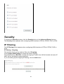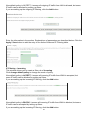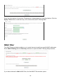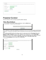
1
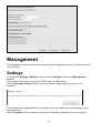
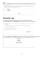
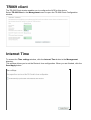
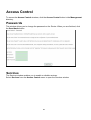
TeleWell TW-EAV510
XDSL ROUTER
RELEASE 1.3
USER MANUAL
CONTENTS
Device Installation ....................................................................................................................... 4
Power on Router ......................................................................................................................... 4
Factory Reset Button .................................................................................................................. 4
Network Connections .................................................................................................................. 5
Configuration ............................................................................................................................... 5
Web-based Configuration Utility ................................................................................................. 6
Device Info .................................................................................................................................. 7
Summary ..................................................................................................................................... 8
WAN ............................................................................................................................................ 8
Statistics ...................................................................................................................................... 9
Route ........................................................................................................................................ 12
ARP ........................................................................................................................................... 12
DHCP ........................................................................................................................................ 12
Quick Setup .............................................................................................................................. 12
Advanced Setup ........................................................................................................................ 13
Layer2 Interface ........................................................................................................................ 13
WAN Service ............................................................................................................................. 17
LAN ........................................................................................................................................... 21
Ethernet Port ............................................................................................................................. 23
NAT ........................................................................................................................................... 23
Security ..................................................................................................................................... 26
Parental Control ........................................................................................................................ 29
3G ............................................................................................................................................. 31
Quality of Service ...................................................................................................................... 33
Routing ...................................................................................................................................... 35
DNS .......................................................................................................................................... 37
DSL ........................................................................................................................................... 40
UPNP ........................................................................................................................................ 41
DNS Proxy ................................................................................................................................ 41
DLNA ........................................................................................................................................ 42
Storage service ......................................................................................................................... 42
Interface Grouping .................................................................................................................... 43
IP Tunnel ................................................................................................................................... 44
IPSec ........................................................................................................................................ 45
Power Management .................................................................................................................. 46
2
Multicast .................................................................................................................................... 47
Wireless .................................................................................................................................... 48
Basic ......................................................................................................................................... 48
Security ..................................................................................................................................... 49
MAC Filter ................................................................................................................................. 50
Wireless Bridge ......................................................................................................................... 51
Advanced .................................................................................................................................. 51
Station Info ................................................................................................................................ 52
Diagnostics ............................................................................................................................... 53
Diagnostics ............................................................................................................................... 53
Fault Management .................................................................................................................... 53
Management ............................................................................................................................. 54
Settings ..................................................................................................................................... 54
System Log ............................................................................................................................... 55
Security Log .............................................................................................................................. 56
TR069 client .............................................................................................................................. 57
Internet Time ............................................................................................................................. 57
Access Control .......................................................................................................................... 58
Reboot ...................................................................................................................................... 60
Tools ......................................................................................................................................... 60
Troubleshooting ........................................................................................................................ 61
Glossary .................................................................................................................................... 63
3
11
Device Installation
The TW-EAV510 connects two separate physical interfaces, an xDSL (WAN) and an Ethernet
(LAN) interface. Place the Router in a location where it can be connected to the various
devices as well as to a power source. The Router should not be located where it will be
exposed to moisture or excessive heat. Make sure the cables and power cord are placed
safely out of the way so they do not create a tripping hazard. As with any electrical appliance,
observe common sense safety procedures.
The Router can be placed on a shelf or desktop, ideally you should be able to see the LED
indicators on the front if you need to view them for troubleshooting.
Power on Router
The Router must be used with the power adapter included with the device.
1. Insert the DC Power Adapter cord into the power receptacle located on the rear panel of the
Router and plug the adapter into a suitable nearby power source.
2. Depress the Power button into the on position. You should see the Power LED indicator light
up and remain lit. The Status LED should light solid green and begin to blink after a few
seconds.
3. If the Ethernet port is connected to a working device, check the LAN LED indicators to make
sure the connection is valid. The Router will attempt to establish the xDSL connection, if the
xDSL line is connected and the Router is properly configured this should light up after several
seconds. If this is the first time installing the device, some settings may need to be changed
before the Router can establish a connection.
Factory Reset Button
The Router may be reset to the original factory default settings by using a ballpoint or paperclip
to gently push down the reset button in the following sequence:
1. Press and hold the reset button while the device is powered off.
2. Turn on the power.
3. Wait for 10 seconds and then release the reset button.
Remember that this will wipe out any settings stored in flash memory including user account
information and LAN IP settings. The device settings will be restored to the factory default IP
address 192.168.0.254 and the subnet mask is 255.255.255.0, the default management
Username is “admin” and the default Password is “admin.”
4
Network Connections
Connect xDSL Line
Use the xDSL cable included with the Router to connect it to a telephone wall socket or
receptacle. Plug one end of the cable into the xDSL port (RJ-11 receptacle) on the rear panel
of the Router and insert the other end into the RJ-11 wall socket. If you are using a low pass
filter device, follow the instructions included with the device or given to you by your service
provider. The xDSL connection represents the WAN interface, the connection to the Internet. It
is the physical link to the service provider’s network backbone and ultimately to the Internet.
Connect Router to Ethernet
The Router may be connected to a single computer or Ethernet device through the
10BASE-TX Ethernet port on the rear panel. Any connection to an Ethernet concentrating
device such as a switch or hub must operate at a speed of 10/100 Mbps only. When
connecting the Router to any Ethernet device that is capable of operating at speeds higher
than 10Mbps, be sure that the device has auto-negotiation (NWay) enabled for the connecting
port. Use standard twisted-pair cable with RJ-45 connectors. The RJ-45 port on the Router is a
crossed port (MDI-X). Follow standard Ethernet guidelines when deciding what type of cable to
use to make this connection. When connecting the Router directly to a PC or server use a
normal straight-through cable. You should use a crossed cable when connecting the Router to
a normal (MDI-X) port on a switch or hub. Use a normal straight-through cable when
connecting it to an uplink (MDI-II) port on a hub or switch. The rules governing Ethernet cable
lengths apply to the LAN to Router connection. Be sure that the cable connecting the LAN to
the Router does not exceed 100 meters.
Hub or Switch to Router Connection
Connect the Router to an uplink port (MDI-II) on an Ethernet hub or switch with a
straight-through cable. If you wish to reserve the uplink port on the switch or hub for another
device, connect to any on the other MDI-X ports (1x, 2x, etc.) with a crossed cable.
Computer to Router Connection
You can connect the Router directly to a 10/100BASE-TX Ethernet adapter card (NIC) installed
on a PC using the Ethernet cable provided.
Configuration
This section will show you how to configure your new Router using the web-based
configuration utility.
5
Web-based Configuration Utility
Connect to the Router
The default IP address for xDSL MODEM is: 192.168.0.254; The Subnet Mask is:
255.255.255.0. Users can configure xDSL MODEM through an Internet browser. xDSL
MODEM can be used as gateway and DNS server; users need to set the computer’s TCP/IP
protocol as follow:
1. Set the computer IP address at same segment of xDSL MODEM, such as set the IP
address of the network card to one of the “192.168.0.100”~ “192.168.0.200”.
2. Set the computer’s gateway the same IP address as the xDSL Modem’s.
3. Set computer’s DNS server the same as xDSL Modem’s IP address or that of an effective
DNS server.
To access the configuration utility, open a web-browser such as Internet Explorer and enter the
IP address of the router (192.168.0.254).
Type “admin” for the User Name and “admin” in the Password field. If you get a Page Cannot
be Displayed error, please refer to the Troubleshooting section for assistance.
6
Device Info
To access the Device Info window, click either the Device Info or Summary button in the
Device Info directory. The following page opens:
7
Summary
To access the Router’s first Summary window, click the Summary button in the Device Info
directory.
This window displays the current status of your DSL connection, including the software version,
LAN IP address, and DNS server address.
WAN
To access the WAN Info window, click the WAN button in the Device Info directory.
This window displays the current status of your WAN connection.
8
Statistics
The Statistics menu contains statistical information about the LAN, WAN service, and Optical.
Select Statistics in the Device Info menu to open the Statistics submenu.
LAN
The LAN window displays the statistics for the information received and transmitted over the
LAN interface.
Click LAN in the Statistics submenu to open the LAN window;
WAN Service
The WAN window displays the statistics for the information received and transmitted over the
WAN interface.
Click WAN Service in the Statistics submenu to open the WAN window;
9
xTM
To access the Device Info – xTM window, click the xTM button in the Device Info directory.
This read-only window displays xTM info.
xDSL
To access the Device Info – XDSL window, click the xDSL button in the Device Info
directory.
This read-only window displays xDSL info.
10
11
Route
To access the Device Info – Route window, click the Route button in the Device Info
directory.
This read-only window displays routing info.
ARP
To access the Device Info – ARP window, click the ARP button in the Device Info directory.
This read-only window displays Address Resolution Protocol info.
DHCP
To access the Device Info – DHCP Leases window, click the DHCP button in the Device Info
directory.
This read-only window displays DHCP lease info.
Quick Setup
The Quick Setup will help you to configure the device eazily. If you want Automatic
Configuration, click the checkbox of Automatic Configuration. When you are finished, click
the Apply/Save button to save.
12
Advanced Setup
This chapter include the more advanced features used for network management and security
as well as administrative tools to manage the Router, view status and other information used to
examine performance and for troubleshooting.
Layer2 Interface
To access the DSL ATM Interface Configuration window, click the ATM Interface button in
the Layer2 Interface directory.
This window is used to configure the ATM interface. You can add and delete ATM interface on
this window.
If you are setting up the ATM interface for the first time, click the Add button.
13
ATM Interface
The ATM PVC Configuration window allows you to set up ATM PVC configuration. Enter
Virtual Path Identifier, and Virtual Channel Identifier. The VPI and VCI values should be
provided by your ISP. This window also allows you to select DSL Link Type, PPPoA、IPoA and
EoA (EoA is for PPPoE, IPoE, and Bridge)
Use the drop-down menu to select the desired Encapsulation Mode.
Click the Apply / Save button to save.
14
VDSL2 (ptm) interface
The VDSL2 (ptm) interface Configuration window enables you to add, delete, or modify up to
one VDSL WAN Layer 2 interface connections.
Click VDSL2 (ptm) Interface in the Layer2 Interface menu to open the VDSL(ptm) WAN
Interface Configuration window
VDSL WAN Configuration
If you have selected to add or modify a VDSL interface connection, the VDSL WAN
Configuration window opens. Click the Apply/Save button to save.
15
ETH interface
The ETH WAN Interface Configuration window enables you to add, delete, or modify up to one
ETH WAN Layer 2 interface connections.
Click ETH Interface in the Layer2 Interface menu to open the ETH WAN Interface
Configuration window
ETH WAN Configuration
If you have selected to add or modify an ETH interface connection, the ETH WAN
Configuration window opens
16
WAN Service
To access the Wide Area Network (WAN) Service Setup window, click the WAN Service
button in the Advanced Setup directory.
This window is used to configure the WAN interface. You can add and delete WAN interface
on this window.
If you are setting up the WAN interface for the first time, click the Add button.
The WAN Service Interface Configuration Configuration window allows select a layer 2
interface for this service. Click the Next button to continue
This window allows you to select the appropriate connection type. The choices include PPP
over ATM (PPPoA), PPP over Ethernet (PPPoE), IP over Ethernet (IPoE), IP over ATM (IPoA),
and Bridging.
WAN Service Configuration – PPPoE
Click the PPP over Ethernet (PPPoE) radio button on this window. This window also allows
you to use the drop-down menu to enable IPv6 service. Click the Next button to continue.
17
WAN Service Configuration – PPPoE
This window allows you to set the username and the password for your PPP connection. This
information is obtained from your ISP. Additional settings on this window will also depend on
your ISP. And you can input 2nd IP on this page. Click the Next button to continue.
18
WAN Service Configuration – IPoE
This window allows you to configure the WAN IP settings. This information is obtained from
your ISP. Click the Next button to continue
19
WAN Service Configuration – Bridging
Click the Bridge radio button on this window. Click the Next button to continue.
20
LAN
You can configure the LAN IP address to suit your preference. Many users will find it
convenient to use the default settings together with DHCP service to manage the IP settings
for their private network. The IP address of the Router is the base address used for DHCP. In
order to use the Router for DHCP on your LAN, the IP address pool used for DHCP must be
compatible with the IP address of the Router. The IP addresses available in the DHCP IP
address pool will change automatically if you change the IP address of the Router.
LAN setting
To access the Local Area Network (LAN) Setup window, click the LAN button in the
Advanced Setup directory.
This window allows you to set up a LAN interface. When you are finished, click the Apply /
Save button.
21
IPv6 Autoconfig
The IPv6 Autoconfig window enables you to configure the settings for the LAN interface with
IPv6.
Click IPv6 Autoconfig in the LAN submenu to open the IPv6 Autoconfig window;
This window allows you to configure IPv6. When you are finished, click the Apply / Save
button.
22
Ethernet Port
To access the Ethernet Port window, click the Ethernet Port button in the Advanced Setup
submenu. You can configure the Media Type of Ethernet port in the new page and it will show
you the Link Status of each Ethernet port. When you are finished, click the Save/Apply button
NAT
Virtual Servers
Select Virtual Servers from the Advanced Setup menu to open the NAT submenu.
If you have selected to Add a virtual server, the Add NAT – Virtual Servers window opens
23
Port Triggering
Some applications such as games, video conferencing, remote access applications and others
require that specific ports in the Router's firewall be opened for access by the applications. You
can configure the port settings from this screen by selecting an existing application or creating
your own (Custom application).
Click the Add button to configure port triggering.
You can configure the port settings on this window by clicking the Select an application radio
button and then using the drop-down list to choose an existing application, or by clicking the
Custom application radio button and entering your own Application Rule in the field provided.
Click Save/Apply when you are finished with the port setting configuration. The new
Application Rule will appear in the Port Triggering table.
24
DMZ Host
Since some applications are not compatible with NAT, the Router supports use of a DMZ IP
address for a single host on the LAN. This IP address is not protected by NAT and will
therefore be visible to agents on the Internet with the right type of software. Keep in mind that
any client PC in the DMZ will be exposed to various types of security risks. If you use the DMZ,
take measures (such as client-based virus protection) to protect the remaining client PCs on
your LAN from possible contamination through the DMZ.
To designate a DMZ IP address, type in the IP Address of the server or device on your LAN,
and click the Save/Apply button
ALG
To access the ALG window, click the ALG button in the NAT submenu. You can enable and
disable the ALG functions in the new page. When you are finished, click the Save/Apply
button.
25
Security
To access the Security window, click the Security button in the Advanced Setup directory.
The Security button appears after configuring WAN interface in PPPoA, PPPoE, IPoE or IPoA.
IP Filtering
The IP Filtering button appears when configuring WAN interface in PPPoA, PPPoE, IPoE or
IPoA.
IP Filtering - Outgoing
This window allows you to create a filter rule of Outgoing.
Click change default policy to change the mode of policy.
Now default policy is BLOCK, it means all outgoing IP traffic from LAN is blocked, but some IP
traffic can be accepted by setting up filters.
If you are setting up the outgoing IP filtering, click the Add button.
26
Now default policy is ACCEPT, it means all outgoing IP traffic from LAN is allowed, but some
IP traffic can be blocked by setting up filters.
If you are setting up the outgoing IP filtering, click the Add button.
Enter the information in the section. Explanations of parameters are described below. Click the
Apply / Save button to add the entry in the Active Outbound IP Filtering table.
IP Filtering – Incoming
This window allows you to create a filter rule of Incoming.
Click change default policy to change the mode of policy.
Now default policy is ACCEPT, it means all incoming IP traffic from WAN is accepted, but
some IP traffic can be blocked by setting up filters.
If you are setting up the incoming IP filtering, click the Add button.
Now default policy is BLOCK, it means all incoming IP traffic from WAN is blocked, but some
IP traffic can be accepted by setting up filters.
If you are setting up the incoming IP filtering, click the Add button.
27
Enter the information in the section. Explanations of parameters are described below. Click the
Apply / Save button to add the entry in the Active Inbound IP Filtering table.
MAC filter
The MAC Filtering window enables you to control access to and from specific MAC addresses.
Select MAC Filtering from the Security submenu to open the MAC Filtering Setup window;
If you have selected to Add a MAC filter, the Add MAC Filter window opens
28
Parental Control
Use this window to deny access to specified MAC address.
Time Restriction
If you are setting up the MAC address blocking, click the Add button.
MAC address is a specially formatted text string (xx:xx:xx:xx:xx:xx) that uniquely identification
of a device. This section will allow users to block devices with certain MAC addresses on the
LAN.
To configure for MAC address blocking, enter the username into the Username field, click
Browser’s MAC Address to have MAC address of the LAN device, or click Other MAC
Address and enter a MAC address manually. Tick the checkboxes for the desired individual
days of the week and enter desired Start Blocking Time and End Blocking Time.
Click the Save/Apply button to save the configuration
29
URL Filter
This window allows you to set up URL Filter on the Router.
Choose URL List Type Exclude or Include first and click Add button.
Enter the URL address and port number then click Apply / Save to add the entry to the URL
filter.
30
3G
To access the 3G window, click the 3G button in the Advanced Setup directory.
This window allows you to set up 3G on the Router. When you are finished, click on the
Save/Apply button.
If you want to add new 3G dongle, click driver add button, and the new page will show
you how to configure a new 3G dongle. After you are finished, click on the add button.
31
32
Quality of Service
QoS or Quality of Service allows your Router to help prioritize the data packet flow in your
Router and network. This is very important for time sensitive applications such as VoIP where it
may help prevent dropped calls. Large amounts of non-critical data can be scaled so as not to
affect these prioritized sensitive real-time programs.
To access the QoS – Queue Management Configuration window, click the Quality of
Service button in the Advanced Setup directory.
This window allows you to set up QoS on the Router. When you are finished, click on the
Save/Apply button.
Qos Queue
Click the Add button to add a QoS Queue Configuration table entry.
This window allows you to configure a QoS queue entry and assign it a specific network
interface.
Click the Apply / Save button to save and activate the filter.
33
QoS Classification
Choose Add or Remove to configure network traffic classes.
Use this window to create a traffic class rule to classify the upstream traffic, assign a queue
that defines the precedence and the interface, and optionally overwrite the IP header DSCP
byte. A rule consists of a class name and at least one condition. Please remember that all of
the specified conditions on this window must be met for the rule to take effect.
Click the Apply / Save button to save and activate this rule.
34
Routing
To access the Routing windows, click the Routing button in the Advanced Setup directory.
Default Gateway
Default gateway interface list can have multiple WAN interfaces served as system default
gateways but only one will be used according to the priority with the first being the highest and
the last one the lowest priority if the WAN interface is connected. Priority order can be changed
by removing all and adding them back in again. Click the Apply / Save button when you are
finished.
35
Static Route
Click the Add button on the Routing – Static Route window to access the following window
displayed on the next page.
Enter the static routing information for an entry to the routing table.
Click the Apply / Save button when you are finished.
Policy Routing
Click the Add button on the Policy Routing Setting window to access the following window
displayed on the next page.
Enter the Policy Routing information. Click the Apply / Save button when you are finished.
36
RIP
To activate RIP for the device, select the Enabled radio button for Global RIP Mode. To
configure an individual interface, select the desired RIP version and operation, followed by
placing a check in the 'Enabled' checkbox for the interface. Click the Save/Apply button to
save the configuration, and to start or stop RIP based on the Global RIP mode selected.
DNS
To access the DNS windows, click the DNS button in the Advanced Setup directory. The DNS
button appears when configuring WAN interface in PPPoA, PPPoE, MER or IPoA.
DNS Server
Select DNS Server Interface from available WAN interfaces OR enter static DNS server IP
addresses for the system. In ATM mode, if only single PVC with IPoA or static IPoE protocol is
configured, Static DNS server IP addresses must be entered.
DNS Server Interfaces can have multiple WAN interfaces served as system DNS servers but
only one will be used according to the priority with the first being the highest and the last one
the lowest priority if the WAN interface is connected. Priority order can be changed by
removing all and adding them back in again. Click the Apply / Save button when you are
finished.
37
Dynamic DNS
The Router supports Dynamic DNS (Dynamic Domain Name Service). The Dynamic DNS
service allows a dynamic public IP address to be associated with a static host name in any of
the many domains, allowing access to a specified host from various locations on the Internet.
This is enabled to allow remote access to a host by clicking a hyperlinked URL in the form
hostname.dyndns.org, Many ISPs assign public IP addresses using DHCP, and this can
make it difficult to locate a specific host on the LAN using standard DNS. If for example you are
running a public web server or VPN server on your LAN, this ensures that the host can be
located from the Internet if the public IP address changes. DDNS requires that an account be
setup with one of the supported DDNS providers.
Click Add to see the Add DDNS Settings section.
Enter the required DDNS information, click the Apply / Save button to save the information.
38
Note
DDNS requires that an account be setup with one of the
supported DDNS servers prior to engaging it on the Router.
This function will not work without an accepted account with a
DDNS server.
39
DSL
The DSL window enables you to configure the DSL settings of the gateway.
Select DSL from the Advanced Setup menu to open the DSL Settings window
If you clicked Advanced Settings in the DSL Settings window, the DSL Advanced Settings
window opens
40
If you clicked the Tone Selection button, the ADSL Tone Settings window opens
Note:
The ADSL tone settings should only be configured with the assistance of your ISP.
UPNP
To access the UPnP Configuration window, click the UPnP button in the Advanced Setup
directory.
This window allows you to Config UPnP Proxy. Click the Apply / Save button when you are
finished.
DNS Proxy
To access the DNS Proxy Configuration window, click the DNS Proxy button in the
Advanced Setup directory.
This window allows you to Config DNS Proxy. Click the Apply / Save button when you are
finished.
41
DLNA
Select DLNA from the Advanced Setup menu to open the DLNA window. This window allows
you to config DLNA function. Click the Apply / Save button when you are finished.
Storage service
The Storage Service window displays Storage Device information from USB interface.
Select Storage Service from the Advanced Setup menu to open the Storage Service window
42
Interface Grouping
Interface Group supports multiple ports to PVC and bridging groups. Each group will perform
as an independent network.
To support this feature, you must create mapping groups with appropriate LAN and WAN
interfaces using the Add button. The Remove button will remove the grouping and add the
ungrouped interfaces to the Default group. Only the default group has IP interface.
Click Add to do advanced settings.
To create a new mapping group, enter Group Name, add interfaces to Grouped Interfaces.
Click Apply / Save to save the changes.
43
IP Tunnel
Select IP Tunnel from the Advanced Setup menu to open the IP Tunnel submenu.
IPv6inIPv4
Select IPv6inIPv4 from the IP Tunnel submenu to open the IP Tunneling-6in4 Tunnel
Configuration window
If you click Add, the detail of the IP Tunneling-6in4 Tunnel Configuration window will open
IPv4inIPv6
Select IPv4inIPv6 from the IP Tunnel submenu to open the IP Tunneling-4in6 Tunnel
Configuration window;
If you click Add, the detail of the IP Tunneling-4in6 Tunnel Configuration window will open
44
IPSec
To access the IPSec Tunnel Mode Connections window, click the IPSec button in the
Advanced Setup directory.
This window allows you to configure IPSec.
Click Add New Connection to edit IPSec tunnel mode connections from this page
This window allows you to advanced settings.
45
Power Management
The Power Management window enables you to control of Hardware to evaluate power
consumption.
Select Power Management from the Advanced Setup menu to open the Power Management
window
46
Multicast
To access the IGMP Configuration window, click the Multicast button in the Advanced
Setup directory.
Enter IGMP protocol configuration fields if you want modify default values shown below.
47
Wireless
Basic
The Basic menu enables you to configure basic features of the wireless LAN interface.
Select Basic from the Wireless menu to open the basic submenu;
48
Security
This page allows you to configure security features of the wireless LAN interface. You may
setup configuration manually or through WiFi Protected Setup(WPS)
You can select to configure WEP encryption, Shared, 802.1x, WPA, and WPA2 authentication.
49
MAC Filter
This page can help you to allow or deny certain MAC addresses to pass through or block out.
Click Add to see the following page.
Enter MAC Address and click Apply / Save to add the MAC address to MAC filter.
50
Wireless Bridge
The Wireless Bridge menu enables you to configure wireless bridge features of the wireless
LAN interface.
Select Wireless Bridge from the Wireless menu to open the wireless bridge submenu
Advanced
This page allows you to configure advanced wireless LAN interface. Configuring these settings
may increase the performance of your router but if you are not familiar with networking devices
and protocols, this section should be left at its default settings.
Click Apply / Save to save the settings.
51
Station Info
This page shows the authenticated wireless stations and their status.
Click Refresh to update the information.
52
Diagnostics
Diagnostics
Your modem is capable of testing your DSL connection with access to Diagnostics.
This window is used to test connectivity of the Router.
Fault Management
Fault Management enables you to test the connectivity of the xDSL PTM mode.
Note:
Fault management should only be run with assistance from your ISP.
Select Fault Management from the Diagnostics menu to open the 802.1ag Connectivity Fault
Management window
53
Management
The Management directory features an array of options designed to help you get the most out
of your Router.
Settings
To access the Settings - Backup window, click the Settings button in the Management
directory.
This window allows you to backup your DSL Router configurations.
Click the Backup Settings button to save your Router configurations to a file on your
computer.
This window allows Update DSL router settings. You may update your router settings using
your saved files.
Click the Update button to update your Router configurations with a file on your computer.
54
This window allows Restore DSL router settings to the factory defaults.
Click the Restore DSL Settings button to restore DSL router settings to the factory defaults.
System Log
The System Log windows enable you view and configure the system log of this device.
Select System Log in the Management menu to open the System Log window
If you clicked View System Log in the System Log window, the System Log information
window opens;
If you clicked Configure System Log in the System Log window, the Configuration window
55
opens;
Note: Configuring the system log should be done with assistance from your ISP.
Security Log
The System Log windows enable you view the security log of this device.
Select Security Log in the Management menu to open the Security Log window;
If you clicked View in the Security Log window, the Security Log information window opens;
56
TR069 client
The TR-069 Client window enables you to configure the ACS for this device
Select TR-069 Client in the Management menu to open the TR-069 Client-Configuration
window;
Internet Time
To access the Time settings window, click the Internet Time button in the Management
directory.
This window allows you to set the Router’s time configuration. When you are finished, click the
Save/Apply button.
57
Access Control
To access the Access Control windows, click the Access Control button in the Management
directory.
Passwords
This window allows you to change the password on the Router. When you are finished, click
the Save/Apply button.
Services
The Services window enables you to enable or disable services
Select Services from the Access Control menu to open the Services window
58
IP Addresses
The IP Address Access Control mode, if enabled, permits access to local management
services from IP addresses contained in the Access Control List. If the Access Control mode is
disabled, the system will not validate IP addresses for incoming packets. The services are the
system applications listed in the Service Control List.
To access this window, click the IP addresses button in the Access Control directory.
Click the Add button, access the following window displayed on the next page.
59
Input the IP Address and Subnet Mask which you want to configure, and then click Apply to
enable this IP Address.
Reboot
To access this window, click the Reboot button in the Management directory.
To save your settings and reboot the system, click the Reboot button.
Tools
This page will help you to diagnostic the status of your Network. You can use “Ping”, “Trace
Route” and “Nslookup” methods in this page. After you input the IP address or Domain name,
click "Ping”, "Trace Route" or "Nslookup" button.
60
Troubleshooting
1.
How do I configure my TW-EAV510 Router without the CD-ROM?
• Connect your PC to the Router using an Ethernet cable.
• Open a web browser and enter the address http://192.168.0.254
• The default username is ‘admin’ and the default password is ‘admin’.
• If you have changed the password and cannot remember it, you will need to reset the
Router to the factory default setting (see question 2), which will set the password back to
‘admin’.
Note:
Please refer to the next section “Networking Basics” to check your PC’s IP configuration if
you can’t see the login windows.
2.
How do I reset my Router to the factory default settings?
•
•
•
Ensure the Router is powered on.
Press and hold the reset button on the back of the device for approximately 10 seconds.
This process should take around 30~60 seconds.
3.
What can I do if my Router is not working correctly?
There are a few quick steps you can take to try and resolve any issues:
• Follow the directions in Question 2 to reset the Router.
• Check that all the cables are firmly connected at both ends.
• Check the LEDs on the front of the Router. The Power indicator should be on, the Status
indicator should flash, and the DSL and LAN indicators should be on as well.
• Please ensure that the settings in the Web-based configuration manager, e.g. ISP
username and password, are the same as the settings that have been provided by your ISP.
4.
Why can’t I get an Internet connection?
For xDSL ISP users, please contact your ISP to make sure the service has been
enabled/connected by your ISP and that your ISP username and password are correct.
5.
•
•
•
•
What can I do if my router can’t be detected by running installation CD?
Ensure the Router is powered on.
Check that all the cables are firmly connected at both ends and all LEDs work correctly.
Ensure only one network interface card on your PC is activated.
Click on Start > Control Panel > Security Center to disable the setting of Firewall.
61
Note: There might be a potential security issue if you disable the setting of Firewall on your PC. Please
remember to turn it back on once you have finished the whole installation procedure and can surf on
Internet without any problem
62
Glossary
Numerics
10/100Base-T
The most widely used standard for Ethernet over twisted pair or copper-based computer networking. Runs at 10
Mb/s, 100 Mb/s, and 1000 Mb/s (1 Gb/s) respectively.
A
ACS
Auto-Configuration Server
ADSL
Asymmetric Digital Subscriber Line
ALG
Application-Level Gateway
ATM
Asynchronous Transfer Mode
C
CHAP
Challenge-Handshake Authentication Protocol
CPE
Customer Premises Equipment
D
DDNS
Dynamic Domain Name System
DHCP
Dynamic Host Configuration Protocol
DNS
Domain Name System
DSCP
Differentiated Services Code Point
DSL
Digital Subscriber Line
Dynamic Routing
The capability of a system, through which routes are characterized by their destination, to alter the path that the
route takes through the system in response to a change in conditions.
63
E
Ethernet
A family of frame-based computer networking technologies for local area networks (LANs).
F
Firewall
An integrated collection of security measures designed to prevent unauthorized electronic access to a networked
computer system.
G
Gateway
A network node equipped for interfacing with another network that uses different protocols.
H
HDSL
High-Rate Digital Subscriber Line
HTML
Hyper Text Markup Language
I
IP
Internet Protocol
ISP
Internet Service Provider
K
Kb/s
Kilo bit per second; a data rate unit.
L
L2TP
Layer 2 tunneling protocol; a tunneling protocol used to support virtual private networks (VPNs).
LAN
Local Area Network
M
MAC
Media Access Control
Mb
Megabit; a unit of information commonly used to express the rate data is transferred.
MTU
Maximum Transmission Unit
N
64
NAT
Network Address Translation
Net mask
The designated IP address routing prefix for a network of computers and devices.
NIC
Network Interface Controller
NTP
Network Time Protocol
O
OAM
Operations, Administration, and Maintenance
P
PAP
Password Authentication Protocol
Ping
A computer network tool used to test whether a particular host is reachable across an IP network.
PPP
Point-to-Point Protocol
PPPoE
Point-to-Point Protocol over Ethernet
PVC
Permanent Virtual Circuit
Q
QoS
Quality of Service
S
Subnet
See Net mask.
T
TCP
Transmission Control Protocol
Telnet
Telecommunications network; a network protocol used on the internet or local area network (LAN) connections.
U
65
UDP
User Datagram Protocol
UPnP
Universal Plug and Play
URL
Uniform Resource Locator
USB
Universal Serial Bus
V
VCI
Virtual Circuit ID
xDSL
Very High Bit rate Digital Subscriber Line
VLAN
Virtual Local Area Network
VPI
Virtual Path ID
W
WAN
Wide Area Network
66