1
SUPER
M14T
Mobile Rack
USER'S GUIDE
Rev. 1.0a
®
M14T Mobile Rack User's Guide
The information in this User’s Manual has been carefully reviewed and is believed to be accurate.
The vendor assumes no responsibility for any inaccuracies that may be contained in this document,
makes no commitment to update or to keep current the information in this manual, or to notify any
person or organization of the updates. Please Note: For the most up-to-date version of this
manual, please see our web site at www.supermicro.com.
Super Micro Computer, Inc. ("Supermicro") reserves the right to make changes to the product
described in this manual at any time and without notice. This product, including software, if any,
and documentation may not, in whole or in part, be copied, photocopied, reproduced, translated or
reduced to any medium or machine without prior written consent.
IN NO EVENT WILL SUPERMICRO BE LIABLE FOR DIRECT, INDIRECT, SPECIAL, INCIDENTAL,
SPECULATIVE OR CONSEQUENTIAL DAMAGES ARISING FROM THE USE OR INABILITY TO
USE THIS PRODUCT OR DOCUMENTATION, EVEN IF ADVISED OF THE POSSIBILITY OF
SUCH DAMAGES. IN PARTICULAR, SUPERMICRO SHALL NOT HAVE LIABILITY FOR ANY
HARDWARE, SOFTWARE, OR DATA STORED OR USED WITH THE PRODUCT, INCLUDING THE
COSTS OF REPAIRING, REPLACING, INTEGRATING, INSTALLING OR RECOVERING SUCH
HARDWARE, SOFTWARE, OR DATA.
Any disputes arising between manufacturer and customer shall be governed by the laws of Santa
Clara County in the State of California, USA. The State of California, County of Santa Clara shall
be the exclusive venue for the resolution of any such disputes. Super Micro's total liability for all
claims will not exceed the price paid for the hardware product.
California Best Management Practices Regulations for Perchlorate Materials: This Perchlorate
warning applies only to products containing CR (Manganese Dioxide) Lithium coin cells. “Perchlorate
Material-special handling may apply. See www.dtsc.ca.gov/hazardouswaste/perchlorate”
WARNING: Handling of lead solder materials used in this
product may expose you to lead, a chemical known to
the State of California to cause birth defects and other
reproductive harm.
Manual Revision 1.0a
Release Date: February 20, 2009
Unless you request and receive written permission from Super Micro Computer, Inc., you may not
copy any part of this document.
Information in this document is subject to change without notice. Other products and companies
referred to herein are trademarks or registered trademarks of their respective companies or mark
holders.
Copyright © 2009 by Super Micro Computer, Inc.
All rights reserved.
Printed in the United States of America
ii
Safety Information and Technical Specifications
Table of Contents
Chapter 1 Introduction
1-1
Overview ......................................................................................................... 1-1
1-2
Product Features ........................................................................................... 1-1
Operating Systems Supported ........................................................................ 1-2
System Monitoring .......................................................................................... 1-2
1-3
An Important Note to the User ........................................................................ 1-2
1-4
Contacting Supermicro .................................................................................... 1-3
1-5
Returning Merchandise for Service................................................................. 1-4
Chapter 2 SASM14V Backplane
2-1
SASM14V Front Connectors and Jumpers..................................................... 2-1
Front Connectors ............................................................................................ 2-1
Front LED Indicators ....................................................................................... 2-1
2-2
SASM14V Rear Connectors and Jumpers ..................................................... 2-2
Rear Side Connectors ..................................................................................... 2-2
Rear Jumpers.................................................................................................. 2-3
Chapter 3 Installation Instructions
3-1
Packing List ..................................................................................................... 3-1
3-2
Tools Needed .................................................................................................. 3-1
3-3
Important Safety Guidelines ............................................................................ 3-1
3-4
Cooling Fan Installation and Removal ........................................................... 3-3
3-5
HDD Installation ............................................................................................. 3-4
Removing the HDD Tray ................................................................................. 3-4
Installing the Hard Disk Drive into the Drive Tray .......................................... 3-5
Installing Hard Disk Drive Trays into the Mobile Rack ................................... 3-6
3-6
Rear Panel Removal and Installation (Optional) ............................................ 3-7
iii
Safety Information and Technical Specifications
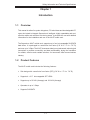
Chapter 1
Introduction
1-1
Overview
This manual is written for system integrators, PC technicians and knowledgeable PC
users who intend to integrate Supermicro's intelligent, highly expandable and costeffective mobile rack solutions into their systems. It provides the user with detailed
information for the installation and use of the M14T mobile rack.
The Supermicro M14T mobile rack, supports up to four hot-swappable SAS/SATA
hard drives. It is packaged in a small size form factor (5.8" W x 1.7" H x 7.9" D)
and runs up to 3 Gbps. The M14T showcases today's most advanced technological
innovations in modular connectivity and data transferability, laying the foundation
for reliable, effective and scalable solutions for tomorrow's data communications
industry.
1-2
Product Features
The M14T mobile rack includes the following features:
•
Slim design with a small size form factor (SFF) (5.8" W x 1.7" H x 7.9" D)
•
Supports 4 x 2.5" hot-swappable SFF HDDs
•
Supports up to 5V/10A (Average) and 12V/10A (Average)
•
Operates at up to 3 Gbps
•
Supports SAS/SATA
1-1
M14T Mobile Rack User's Guide
Operating Systems Supported
For the most up-to-date information visit the Supermicro Web site at www.supermicro.com
•
Windows 2000, Windows XP, and Windows 2003
•
Linux: Red Hat and SuSE
•
Upgradable in the future
System Monitoring
•
•
1-3
Overheat/Fan Fail LED indicators and an audible alarm indicating a system
overheat or fan failure
Drive Activity LED indicates the activity status of each disk drive
An Important Note to the User
The pictures or graphics shown in this User's Guide were based upon the latest
PCB revision available at the time of the publishing of this manual. The M14T
mobile rack you've received may or may not look exactly the same as the graphics
shown in this manual.
1-2
Safety Information and Technical Specifications
1-4
Contacting Supermicro
Headquarters
Address:
Super Micro Computer, Inc.
980 Rock Ave.
San Jose, CA 95131 U.S.A.
Tel:
+1 (408) 503-8000
Fax:
+1 (408) 503-8008
Email:
[email protected] (General Information)
[email protected] (Technical Support)
Web Site:
www.supermicro.com
Europe
Address:
Super Micro Computer B.V.
Het Sterrenbeeld 28, 5215 ML
's-Hertogenbosch, The Netherlands
Tel:
+31 (0) 73-6400390
Fax:
+31 (0) 73-6416525
Email:
[email protected] (General Information)
[email protected] (Technical Support)
[email protected] (Customer Support)
Asia-Pacific
Address:
Super Micro Computer, Inc.
4F, No. 232-1, Liancheng Rd.
Chung-Ho 235, Taipei County
Taiwan, R.O.C.
Tel:
+886-(2) 8226-3990
Fax:
+886-(2) 8226-3991
Web Site:
www.supermicro.com.tw
Technical Support:
1-3
M14T Mobile Rack User's Guide
1-5
Returning Merchandise for Service
A receipt or copy of your invoice marked with the date of purchase is required before any warranty service will be rendered. You can obtain service by calling your
vendor for a Returned Merchandise Authorization (RMA) number. When returning
to the manufacturer, the RMA number should be prominently displayed on the
outside of the shipping carton, and mailed prepaid or hand-carried. Shipping and
handling charges will be applied for all orders that must be mailed when service
is complete.
For faster service, RMA authorizations may be requested online (http://www.supermicro.com/support/rma/).
Whenever possible, repack the mobile rack in the original Supermicro carton, using
the original packaging material. If these are no longer available, be sure to pack the
mobile rack securely, using packaging material to surround the mobile rack so that
it does not shift within the carton and become damaged during shipping.
This warranty only covers normal consumer use and does not cover damages incurred in shipping or from failure due to the alteration, misuse, abuse or improper
maintenance of products.
During the warranty period, contact your distributor first for any product problems.
1-4
Safety Information and Technical Specifications
Chapter 2
SASM14V Backplane
2-1
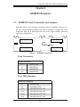
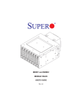
SASM14V Front Connectors and Jumpers
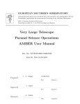
Backplane layout: The following information reflects SASM14V Revision 1.0,
the most current release available at the time of publication. Always refer to the
Supermicro Web site at www.supermicro.com for the latests updates, parts and
supported configurations.
J3
J1
SAS/SATA #2
SAS/SATA #0
D14
D12
D3 D4
SUPER
J2
SAS/SATA #1
R
SASM14V
J4
SAS/SATA #3
D13
D15
Figure 2-1: SASM14V Front View
Front Connectors
Front Connectors
J1
SAS/SATA #0
J2
SAS/SATA #1
J3
SAS/SATA #2
J4
SAS/SATA #3
Front LED Indicators
Front LED Indicators
D3
Overheat LED
D4
Fan Failure LED
D12
SAS/SATA #0 ACT LED
D13
SAS/SATA #1 ACT LED
D14
SAS/SATA #2 ACT LED
D15
SAS/SATA #3 ACT LED
2-1
M14T Mobile Rack User's Guide
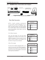
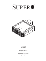
2-2
SASM14V Rear Connectors and Jumpers
JP26
JP42
JP22
1
1
ACT In
Fan
J11
1
SAS In
+5V
GND
GND
+12V
4-Pin PWR
JP10
JP25
JP18
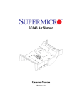
Figure 2-2: Rear Connectors and Jumpers
Rear Side Connectors
4-pin Power Connector
Pin Definitions
JP10:
4-pin
power
connector
The 4-pin power connector designated JP10, is
located on the rear side of the SASM14V backplane. This power connector must be connected
to your power supply in order to provide adequate
power to the backplane. See the table on the right
for pin definitions.
Pin#
Definition
1
+12V
2
Ground
3
Ground
4
+5V
JP11: SAS-In Connector
JP22: 3-pin Fan Header. The 3-pin fan header
designated JP22, located on the rear side of the
SASM14V backplane. Connect a cable to the fan
header to provide cooling to the backplane. See
the table on the right for pin definitions.
Fan Header
Pin Definitions (JP22)
Pin#
Definition
1
Ground
2
+12V
3
Tachometer
JP26: ACT-In Header
Act-In Header
Pin Definitions (JP26)
The 4-pin Act-In header designated JP26, is located on the rear side of the SASM14V backplane.
It indicates the activity status of the SAS/SATA slots
that are on the front of the backplane. See the table
on the right for pin definitions.
2-2
Pin#
Definition
Open
Act-In#0-#3 (Default)
1
Act-In#0
2
Act-In#1
3
Act-In#2
4
Act-In#3
Safety Information and Technical Specifications
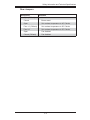
Rear Jumpers
Description
Definition
Open (*Default)
Normal
Closed
Buzzer reset
Open
Set overheat temperature to 45º Celcius
Pins 1-2 (*Default)
Set overheat temperature to 50º Celcius
Pins 2-3
Set overheat temperature to 55º Celcius
Open
Fan disabled
Closed (*Default)
Fan disabled
2-3
Safety Information and Technical Specifications
Chapter 3
Installation Instructions
3-1
Packing List
Examine the following items that are included in your shipping package. If any items
are missing or damaged, please contact your retailer immediately.
•
One 4-drive mobile rack cage (CSE-M14 ((B)) P)
•
Four hot-swappable 2.5" hard disk drive (HDD) trays
•
One cooling fan assembly (40MM)
•
One screw set for 4 HDDs
•
One SAS/SATA backplane (CSE-SAS-M14EV)
•
One SATA Big4 to individual port fan out cable (CBL-0103)
3-2
Tools Needed
The following tools are needed for the installation of the mobile rack into chassis.
1. Phillips screw driver
2. Antistatic strap (Recommended)
3-3
Important Safety Guidelines
Stop
This product shall only be accessed, assembled and serviced by technically qualified personnel or technicians. To avoid personal injury and property damage, please
carefully follow all the safety guidelines listed on the following pages before accessing or servicing the M14T.
3-1
M14T Mobile Rack User's Guide
Before Accessing the Mobile Rack:
1. Turn off all peripheral devices and the power supply connected to the chassis
and unplug all power cords from the system or the wall outlets.
2. Disconnect all the cables and label the cables for easy identification.
3. Use a grounded wrist strap designed to prevent static discharge when handling components.
4. Save all the screws and fasteners for later use. (If necessary, label these
screws or fasteners for easy identification.)
5. Follow the instructions given in the following section to remove and install the
cooling fan, hard disks and the rear window.
3-2
Safety Information and Technical Specifications
3-4
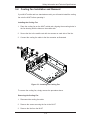
Cooling Fan Installation and Removal
If your M14T mobile rack is a stand-alone model, you will need to install the cooling
fan onto the M14T before operating it.
Installing the Cooling Fan
1. Place the cooling fan on the M14T mobile rack, aligning the mounting holes in
the fan housing with the holes on the mobile rack.
2. Secure the fan to the mobile rack with two screws on each side of the fan.
3. Connect the cooling fan cable to the fan connector as illustrated.
1
12
Figure 3-1: Installing the Cooling Fan
To remove the cooling fan, simply reverse the procedure above:
Removing the Cooling Fan
1. Disconnect the cooling fan cable.
2. Remove the screws securing the fan to the M14T
3. Remove the fan from the M14T.
3-3
M14T Mobile Rack User's Guide
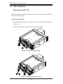
3-5
HDD Installation
Removing the HDD Tray
Before installing the hard disk into the M14T, you will need to remove the HDD
drive trays from the cage.
Removing the HDD Tray
1. Press the release tab toward the right to release the HDD drive tray from the
M14T cage.
2. Once the drive tray is unlocked, pull it out using the handle.
1
Figure 3-2: HDD Tray Release Tab
12
Figure 3-3: Removing Hard Drive Trays
3-4
Safety Information and Technical Specifications
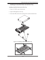
Installing the Hard Disk Drive into the Drive Tray
Installing a Hard Disk Drive into the Drive Tray
1. Place a 2.5" HDD on top of the drive tray.
2. Align the HDD against the drive tray.
3. Secure the HDD onto the drive tray with four M-3 screws as shown below.
1
13
Figure 3-4: Installing an HDD into the Drive Tray
Figure 3-5: HDD Mounting Hole Locations
3-5
M14T Mobile Rack User's Guide
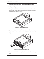
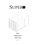
Installing Hard Disk Drive Trays into the Mobile Rack
Installing Drive Trays
1. After you've installed a hard disk drive into a drive tray as described on the
previous page, you are ready to install the HDD into the mobile rack. Insert a
loaded hard drive tray into a drive bay.
Figure 3-6: The M14T Mobile Rack
2. Push the HDD inward until it is fully seated in the drive bay.
3. Press the handle inward toward the mobile rack, pressing it into the locking
position. When the handle is in the correct position, the handle will automatically lock.
13
Figure 3-7: Latching The Hard Drive Tray
4. When the handle is in the correct position, the release tab will automatically
lock.
3-6
Safety Information and Technical Specifications
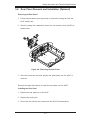
3-6
Rear Panel Removal and Installation (Optional)
Removing the Rear Panel
1. Follow the procedures given previously to remove the cooling fan from the
M14T mobile rack.
2. After the cooling fan is detached, remove the four screws from the M14T as
shown below.
12
13
Figure 3-8: Removing the Rear Panel
3. Once the screws are removed, pull the rear panel away from the M14T to
remove it.
Reverse the steps listed above to install the rear panel onto the M14T.
Installing the Rear Panel
1. Replace the rear panel on on the M14T.
2. Replace the cooling fan
3. Secure the fan with the four screws from the M14T as shown above.
3-7
M14T Mobile Rack User's Guide
Disclaimer (cont.)
The products sold by Supermicro are not intended for and will not be used in life support systems, medical equipment, nuclear facilities or systems, aircraft, aircraft devices,
aircraft/emergency communication devices or other critical systems whose failure to perform be reasonably expected to result in significant injury or loss of life or catastrophic
property damage. Accordingly, Supermicro disclaims any and all liability, and should
buyer use or sell such products for use in such ultra-hazardous applications, it does so
entirely at its own risk. Furthermore, buyer agrees to fully indemnify, defend and hold
Supermicro harmless for and against any and all claims, demands, actions, litigation,
and proceedings of any kind arising out of or related to such ultra-hazardous use or
sale.
3-8