1
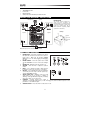
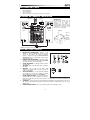
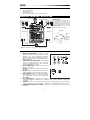
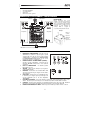
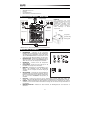
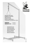
QUICKSTART GUIDE
ENGLISH
GUÍA DE INICIO RÁPIDO
ESPAÑOL
GUIDE D'UTILISATION RAPIDE
FRANÇAIS
GUIDA RAPIDA
ITALIANO
SCHNELLSTART-ANLEITUNG
DEUTSCH
SNELSTARTGIDS
NEDERLANDS
BOX CONTENTS
•
•
•
•
TRUESONIC speaker
Power cable
Quickstart Guide
Safety Instructions & Warranty Information Booklet
CONNECTION DIAGRAM / INSTALLATION
Microphones*
Power
INSTALLATION:
This speaker should be installed on a
stand on the floor, according to its
maximum weight, or suspended from its
suspension points (M10 x 1.5PH, 30mm
length) (see example image). We do
NOT recommend suspending multiple
speakers in a vertical array.
Speaker
Speaker
Example:
Eyebolt
Dust cover
Suspension
point
Mixer*
Power
*Note: Microphones, mixer, and cables are not included.
REAR PANEL OVERVIEW
1.
2.
3.
4.
5.
6.
7.
8.
9.
POWER INPUT – Connect the included power cable to
this input and connect the other end of the cable to a
power source. Make sure the speaker's POWER
7
SWITCH is set to "off" when plugging and unplugging
4
4
8
the cable.
3
POWER SWITCH – Turns the speaker on/off. Make
sure the VOLUME knob is set to "zero" before turning it
5
5
on.
6 9
POWER LED – Illuminates when the speaker is on.
VOLUME – Turn this knob to adjust the speaker's
volume.
INPUT – Use a standard 1/4" TRS or XLR cable (not
included) to connect your sound source to this input.
MIX OUT – Use a standard XLR cable (not included) to
2
1
connect this jack to the input of another speaker (i.e.,
another TRUESONIC speaker).
SIGNAL LIMIT LED – Illuminates when the audio
signal being sent to the speaker is "clipping" or
distorting. If this light illuminates frequently or steadily,
reduce the volume of your sound source.
CONTOUR – Engage (depress) this switch to
emphasize low and high frequencies by +3 dB. Disengage the switch for flatter response for live
performance or for maximum output.
GROUND SWITCH – Press this switch to reduce hum or noise.
2
CONTENIDO DE LA CAJA
•
•
•
•
Altavoz TRUESONIC
Cable de alimentación
Guía de inicio rápido
Folleto de instrucciones de seguridad e información sobre la garantía
DIAGRAMA DE CONEXIÓN / INSTALACIÓN
Micrófonos *
Potencia
INSTALACIÓN:
Este altavoz debe instalarse sobre un
soporte colocado en el suelo, de
acuerdo a su peso máximo, o
suspendido
de
sus
puntos
de
suspensión (M10 x 1.5PH, 30 mm de
longitud) (vea la imagen de ejemplo). NO
recomendamos
suspender
varios
altavoces en un arreglo vertical.
Altavoz
Altavoz
Ejemplo:
Perno de
ojal
Cubierta
antipolvo
Punto de
suspensión
Mezclador *
Potencia
* Nota: No se incluyen micrófonos, mezclador y cable.
VISTA DEL PANEL TRASERO
1.
2.
3.
4.
5.
6.
7.
8.
9.
ENTRADA DE ALIMENTACIÓN – Conecte a esta
entrada el cable de alimentación incluido y luego
conecte el otro extremo del cable al suministro
7
eléctrico. Asegúrese de que el INTERRUPTOR DE
4
4
8
ENCENDIDO esté en "off" (apagado) cuando enchufe
3
y desenchufe el cable.
INTERRUPTOR DE ENCENDIDO – Enciende y apaga
el altavoz. Asegúrese de que la perilla de VOLUMEN
5
5
6 9
esté ajustada a "cero" antes de encenderlo.
LED DE ENCENDIDO – Se ilumina cuando el altavoz
está encendido.
VOLUMEN – Gire esta perilla para ajustar el volumen
del altavoz.
ENTRADA – Use un cable de 1/4" TRS o XLR
2
1
estándar (no incluido) para conectar su fuente de
sonido a esta entrada.
SALIDA DE MEZCLA – Use un cable XLR estándar
(no incluido) para conectar este conector a la entrada
de otro altavoz (por ej. otro altavoz TRUESONIC).
LED DE LÍMITE DE SEÑAL – Se enciende cuando la
señal de audio que se envía al altavoz se "recorta" o
distorsiona. Si esta luz se enciende con frecuencia o en forma permanente, reduzca el volumen de su
fuente de sonido.
CONTORNO – Accione (presione) este interruptor para enfatizar las frecuencias bajas y altas en +3
dB. Libere este interruptor para lograr una respuesta más plana en interpretaciones en vivo o para
máxima salida.
INTERRUPTOR DE TIERRA – Pulse este interruptor para reducir el zumbido o ruido.
3
CONTENU DE LA BOÎTE
•
•
•
•
Haut-parleur TRUESONIC
Câble d'alimentation
Guide d’utilisation simplifié
Consignes de sécurité et informations concernant la garantie
SCHÉMA DE CONNEXION / INSTALLATION
Microphones*
Alimentation électrique
Haut-parleur
INSTALLATION:
Ce haut-parleur doit être installé sur un
pied sur le plancher, en fonction de son
poids maximum, ou suspendu par ses
points d’ancrage (M10 x 1,5 PH, 30 mm de
longueur) (Consultez l’image). Nous NE
RECOMMANDONS PAS de suspendre
plusieurs haut-parleurs ensemble.
Haut-parleur
Exemple :
Boulon à
œil
Housse de
protection
Point
d’ancrage
Alimentation électrique
Console de
mixage *
* Remarque : Microphones, câbles, console de mixage, non inclus.
CARACTÉRISTIQUES DU PANNEAU ARRIÈRE
1.
2.
3.
4.
5.
6.
7.
8.
9.
ENTRÉE D’ALIMENTATION – Branchez le câble
d’alimentation inclus à cette entrée et branchez l’autre
extrémité à une source d’alimentation électrique.
7
Assurez-vous que l’interrupteur de mise en marche est
4
4
8
réglé sur « Off » lorsque vous branchez/débranchez le
3
câble d’alimentation.
INTERRUPTEUR D'ALIMENTATION – Met l’appareil
5
5
6 9
sous et hors tension. Assurez-vous que le bouton du
volume soit complètement fermé (« zéro ») avant de
mettre le haut-parleur sous tension.
DEL D’ALIMENTATION – S’allume lorsque le hautparleur est sous tension..
VOLUME – Ce bouton permet d’ajuster le volume des
haut-parleurs.
2
1
ENTRÉE – Utilisez un câble TRS ou XLR de ¼ po (non
inclus) pour brancher une source audio à cette entrée.
SORTIE MIXAGE – Utilisez un câble XLR standard
(non inclus) pour brancher cette sortie à l’entrée d'un
autre haut-parleur, tel qu’un autre haut-parleur
TRUESONIC.
DEL D'ÉCRÊTEMENT – S’allume pour indiquer
l’écrêtement du signal. Si la DEL clignote ou s’allume de façon constante, diminuez le volume de la
source audio.
CONTOUR – Lorsque cette touche est enfoncée, les basses et hautes fréquences sont accentuées de
+3 dB. Désactivez pour un son plus plat pour les prestations ou pour optimiser la puissance de sortie.
INTERRUPTEUR DE MISE À LA TERRE – Appuyez sur cet interrupteur pour réduire les bruits
indésirables.
4
CONTENUTI DELLA CONFEZIONE
•
•
•
•
Altoparlante TRUESONIC
Cavo di alimentazione
Guida rapida
Istruzioni di sicurezza e garanzia
SCHEMA DEI COLLEGAMENTI / INSTALLAZIONE
Microfoni *
Alimentazione
Altoparlante
INSTALLAZIONE:
Questo
altoparlante
deve
essere
installato su un supporto da pavimento,
in base al suo peso massimo, oppure
appeso servendosi degli appositi punti di
sospensione (M10 x 1,5PH, 30 mm di
lunghezza) (si veda l'immagine di
esempio).
NON
si
consiglia
di
sospendere più altoparlanti in verticale.
Altoparlante
Esempio:
Bullone a
occhiello
Coperchio
antipolvere
Punto di
sospensione
Mixer*
Alimentazione
* Nota bene: microfoni, mixer, altoparlanti e cavi non in dotazione.
PANORAMICA PANNELLO POSTERIORE
1.
2.
3.
4.
5.
6.
7.
8.
9.
INGRESSO DI ALIMENTAZIONE – Collegare il cavo di
alimentazione in dotazione a questo ingresso, quindi
collegare l’altro capo del cavo stesso ad una sorgente
7
di alimentazione. Assicurarsi che l'INTERRUTTORE
4
4
8
DI ALIMENTAZIONE dell'altoparlante sia su "off" al
3
momento di collegare e scollegare il cavo.
INTERRUTTORE DI ALIMENTAZIONE (POWER) –
5
5
6 9
Accende e spegne l'altoparlante. Assicurarsi che la
manopola VOLUME sia impostata su "zero" prima di
accenderlo.
LED DI ALIMENTAZIONE – Si illumina quando
l'altoparlante è acceso.
VOLUME – Girare questa manopola per regolare il
volume dell'altoparlante.
2
1
INGRESSO – Servirsi di un cavo standard TRS o XLR
da 1/4" (non in dotazione) per collegare la fonte audio a
questo ingresso.
USCITA MIX – Servirsi di un cavo standard XLR (non
in dotazione) per collegare questo jack all'ingresso di
un altro altoparlante (ad es. un altro altoparlante
TRUESONIC).
LED LIMITE DI SEGNALE – Si accende quando il segnale audio inviato all'altoparlante "salta" o viene
distorto. Se questa spia si accende spesso o in maniera fissa, ridurre il volume della fonte audio.
CONTOUR – Premere questo interruttore per enfatizzare frequenze alte e basse di +3 dB. Disattivare
l'interruttore per una risposta più blanda per prestazioni dal vivo o per il massimo dell'uscita.
INTERRUTTORE DI MESSA A TERRA – Premere questo interruttore per ridurre il ronzio o rumore.
5
LIEFERUMFANG
•
•
•
•
TRUESONIC Lautsprecher
Netzkabel
Schnellstart-Anleitung
Sicherheitshinweise und Garantieinformationen
ANSCHLUSSÜBERSICHT / MONTAGE
Mikrofone *
Stromversorgung
Lautsprecher
Lautsprecher
MONTAGE:
Dieser Lautsprecher sollte seinem
Maximalgewicht entsprechend auf einem
Bodenstativ montiert oder an den
Aufhängepunkten aufgehängt werden
(M10 x 1.5PH, 30mm Länge) (siehe
Beispielbild).
Mehrere
Lautsprecher
vertikal
aufzuhängen
ist
NICHT
empfehlenswert.
Beispiel:
Ringschraube
Staubabdeckung
Aufhängepunkt
Stromversorgung
Mixer*
* Hinweis: Mikrofone, Mixer und Kabel sind nicht im Lieferumfang enthalten.
ÜBERSICHT RÜCKSEITE
1.
2.
3.
4.
5.
6.
7.
8.
9.
NETZEINGANG – Verbinden Sie das mitgelieferte
Netzkabel mit diesem Eingang und das andere Ende
des Kabels mit einer Stromquelle. Achten Sie darauf,
7
dass der NETZSCHALTER des Lautsprechers auf "off"
4
4
8
steht, wenn Sie das Kabel anschließen oder abstecken.
3
NETZSCHALTER – Schaltet den Lautsprecher ein/aus.
Achten Sie darauf, dass der LAUTSTÄRKE-Regler auf
5
5
6 9
"Null" steht, bevor Sie den Lautsprecher einschalten.
POWER-LED – Leuchtet, wenn der Lautsprecher
eingeschaltet ist.
LAUTSTÄRKE – Drehen Sie diesen Knopf, um die
Lautstärke des Lautsprechers einzustellen.
EINGANG – Verwenden Sie ein handelsübliches 1/4"Klinken- oder XLR-Kabel (nicht im Lieferumfang
2
1
enthalten), um Ihre Tonquelle mit diesem Eingang zu
verbinden.
MIX-AUSGANG – Verwenden Sie ein handelsübliches
XLR-Kabel (nicht im Lieferumfang enthalten), um diese
Buchse mit dem Eingang eines anderen Lautsprechers
(d.h. eines weiteren TRUESONIC Lautsprechers) zu
verbinden.
LIMIT-LED – Leuchtet auf, wenn das an den Lautsprecher gesendete Audiosignal "clippt" oder
verzerrt. Sollte diese LED häufig oder ständig leuchten, reduzieren Sie die Lautstärke Ihrer Tonquelle.
KONTUR – Aktivieren (drücken) Sie diesen Schalter, um niedrige und hohe Frequenzen um +3 dB zu
verstärken. Lösen Sie den Schalter für maximale Leistung oder ein flacheres Ansprechverhalten bei
Live-Auftritten.
ERDUNGSSCHALTER – Drücken Sie diesen Schalter, um Brummgeräusche oder Rauschen zu
reduzieren.
6
INHOUD VAN DE DOOS
•
•
•
•
TRUESONIC luidspreker
Stroomkabel
Snelstartgids
Veiligheidsvoorschriften & boekje met informatie over de garantie
VERBINDINGSDIAGRAM / INSTALLATIE
Microfoons*
Stroom
INSTALLATIE:
Deze luidspreker dient te worden
geplaatst op een vloerstatief aangepast
aan het maximumgewicht, of opgehangen
aan zijn ophangpunten (M10 x 1.5PH, 30
mm lengte) (zie afbeelding als voorbeeld).
Wij raden u NIET aan meerdere
luidsprekers in een verticale opstelling op
te hangen.
Luidspreker
Luidspreker
Voorbeeld:
Oogbout
Stofkap
Ophangpunt
Mengpaneel*
Stroom
*Opmerking: Microfoons, mengpaneel en kabels zijn niet inbegrepen.
OVERZICHT ACHTERPANEEL
1.
2.
3.
4.
5.
6.
7.
8.
9.
POWER INPUT – Sluit de meegeleverde stroomkabel
aan op deze ingang en sluit het andere uiteinde van de
kabel aan op een stroombron. Zorg ervoor dat de
7
POWER-schakelaar van de luidspreker op "off" staat bij
4
4
8
het aansluiten en loskoppelen van de kabel.
3
POWER SWITCH – Schakelt de luidspreker aan/uit.
Zorg ervoor dat de VOLUME-knop op "nul" staat voor
5
5
6 9
het inschakelen.
POWER LED – Brandt wanneer de luidspreker is
ingeschakeld.
VOLUME – Draai deze knop om het luidsprekervolume
aan te passen.
INPUT – Gebruik een standaard 1/4" TRS- of XLRkabel (niet meegeleverd) om uw geluidsbron op deze
2
1
ingang aan te sluiten.
MIX OUT – Gebruik een standaard XLR-kabel (niet
meegeleverd) om deze aansluiting te verbinden met de
ingang van een andere luidspreker (bijv. een andere
TRUESONIC-luidspreker).
SIGNAL LIMIT LED – Gaat branden wanneer het
audiosignaal, verzonden naar de luidspreker, begint te
"clippen" of vervormd is. Als dit lampje vaak of gestaag brandt, verlaag dan het volume van uw
geluidsbron.
CONTOUR – Deze schakelaar activeren (indrukken) om lage en hoge frequenties met +3 dB te
versterken. De schakelaar uitzetten voor een vlakkere respons tijdens live uitvoeringen of voor een
maximale output.
GROUND SWITCH – Druk op deze schakelaar om brom of ruis te verminderen.
7
SPECIFICATIONS
Output Power:
400 W Continuous RMS (335 W LF Class D + 65 W HF Class AB)
800 W Peak (670 W LF + 130 W HF)
Crossover:
2 kHz
Max SPL @ 1m:
122 dB Continuous, 125 dB Peak
Frequency Response:
48 Hz – 18 kHz (@ -10 dB)
Low Frequency:
15" (381 mm) woofer, 2" (51 mm) voice coil
High Frequency:
1" (25 mm) neodymium driver
Coverage:
80°/100° H x 60° V nominal
Connectors:
Input: 1/4" TRS or XLR
Link: XLR
Cabinet:
Polypropylene, trapezoidal
External Control:
Volume control, power-on with LED, clip limiter with LED, ground lift
Power supply:
100-120V/220-240V, 50/60 Hz
Dimensions (H x W x D):
26.7" x 16.9" x 15.2" (679 mm x 430 mm x 385 mm)
Weight (speaker only):
48.6 lbs (22 kg)
THIS DEVICE COMPLIES WITH PART 15 OF THE FCC RULES. OPERATION IS SUBJECT TO THE
FOLLOWING TWO CONDITIONS: (1) THIS DEVICE MAY NOT CAUSE HARMFUL INTERFERENCE, AND (2)
THIS DEVICE MUST ACCEPT ANY INTERFERENCE RECEIVED, INCLUDING INTERFERENCE THAT MAY
CAUSE UNDESIRED OPERATION.
Inrush current at initial switch-on: 3.61 A
Inrush current after power supply interruption: 3.91 A
www.altoprofessional.com
MANUAL VERSION 1.4