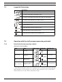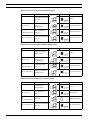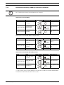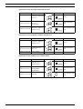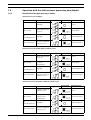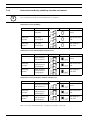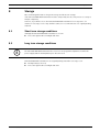
1
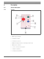
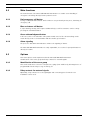
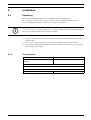
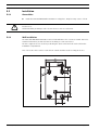
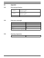
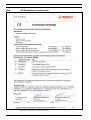
NurseCall N46 Wall Transmitter
en User Manual
NurseCall N46 Wall Transmitter
| en
3
Table of Contents
1
Identification
5
1.1
Document
5
1.2
Customer support addresses
6
2
Generalities
7
2.1
NurseCall System
7
2.2
NurseCall N46 Wall Transmitter
7
3
Safety Instructions
8
3.1
Introduction
8
3.1.1
Principle
8
3.1.2
Importance of safety instructions
8
3.1.3
Disregarding safety rules
8
3.2
Environmental conditions
8
3.3
General safety instructions
9
3.3.1
Observation and information
10
3.4
Special safety instructions
10
4
Description
11
4.1
General description
11
4.1.1
Top view
11
4.2
Main functions
12
4.2.1
Red emergency call button
12
4.2.2
Blue assistance call button
12
4.2.3
Green acknowledgment button
12
4.2.4
Alarm signaling
12
4.3
Options
12
4.3.1
Identification of the nurse group
12
4.3.2
Relay contacts for external signals
12
5
Installation
13
5.1
Unpacking
13
5.1.1
List of contents
13
5.2
Installation
14
5.2.1
Generalities
14
5.2.2
Wall installation
14
5.2.3
Connecting to the power supply
15
5.2.4
Reset
15
5.2.5
Transmitter Identification
15
5.2.6
Operation Check
15
5.2.7
Replacing the battery
16
5.2.8
Configuration and Wiring
17
5.3
Inputs and Outputs
18
5.4
General inputs
18
5.5
Wired Outputs
18
Bosch Security Systems
User Manual
970.030 | v1.1 | 2009.09
4
en |
NurseCall N46 Wall Transmitter
5.6
Wired Inputs
18
5.7
General configuration
19
6
Use
20
6.1
Call for Help
20
6.2
Call for Assistance
20
6.3
Call Acknowledgement (Staff Presence)
21
6.4
Reserve call
21
6.5
Technical Alarm
21
6.6
Caregiver Arrival
21
6.7
Caregiver Departure
22
6.8
Daily Message and Battery Low Message
22
6.9
Error Message
22
7
Operation
23
7.1
Description of the six different states
23
7.2
Legend of illustrations
24
7.3
Operation with the staff presence processing activated
24
7.3.1
Device behavior when pressing a button
24
7.3.2
Device behavior during coded key insertion and removal
27
7.4
Operation with the staff presence processing deactivated
29
7.4.1
Device behavior upon pressing a button
29
7.4.2
Device behavior during coded key insertion and removal
30
8
Storage
31
8.1
Short term storage conditions
31
8.2
Long term storage conditions
31
9
Disposal
32
9.1
Disassembly
32
9.2
Local disposal locations
32
9.3
Returning to the manufacturer
32
9.4
Materials
32
9.4.1
Battery
32
10
Appendix
33
10.1
Electrical specifications
33
10.2
Dimensions and weight
33
10.3
Operating temperature
33
10.4
EC-Declaration of conformity
34
970.030 | v1.1 | 2009.09
User Manual
Bosch Security Systems
NurseCall N46 Wall Transmitter
1
Identification
1.1
Document
Identification | en
Name
No.
User Manual
970.030
5
Table 1.1 Document No.
Version
Description
v1.1 | 2009.09
First Edition
Table 1.2 Version Management
Bosch Security Systems
User Manual
970.030 | v1.1 | 2009.09
6
en | Identification
1.2
NurseCall N46 Wall Transmitter
Customer support addresses
TeleAlarm SA Bosch Group
Bosch Security Systems BV
Rue du Pont 23
Postbus 80002
CH-2300 La Chaux-de-Fonds
NL-5600 JB Eindhoven
Switzerland
Netherlands
Phone: +41 32 327 25 40
Phone: +31 (0)900 8212499
Bosch Security Systems France SAS
Bosch Security Systems nv/sa
Atlantic 361
Torkonjestraat 21F
361, avenue du Général de Gaulle
B-8510 Marke
F-92147 Clamart
Belgium
France
Phone: +32 (0)56 20 02 40
Phone: + 33 (0)825 12 8000
(0,15 € TTC/min from a fixed-line telephone)
Bosch Sicherheitssysteme GmbH
Bosch Security Systems AB
Haus-ServiceRuf
Vestagatan 2
Ingersheimer Straße 16
SE-416 64 Göteborg
D-70499 Stuttgart
Sweden
Germany
Phone: +46 (0)31 722 5300
Phone: +49 (0)711 3653 1000
Bosch Security Systems Ltd
Broadwater Park
North Orbital Road
Denham
UB9 5HN
United Kingdom
Phone: +44 (0)1895 878088
970.030 | v1.1 | 2009.09
User Manual
Bosch Security Systems
NurseCall N46 Wall Transmitter
2
Generalities
2.1
NurseCall System
Generalities | en
7
Alarms and Messages arriving from NurseCall Transmitters such as the NurseCall N46 Wall
Transmitter are managed and stored by the NurseCall Main Unit.
i
2.2
NOTICE!
The document "NurseCall General Overview" explains the system concept.
NurseCall N46 Wall Transmitter
The NurseCall N46 Wall Transmitter is a multifunction terminal radio transmitter, designed for
patients and nursing staff to make an emergency call, summon assistance or cancel a call
directly in the patient’s room. It is part of a NurseCall system, and is easily expandable.
In the NurseCall system, the NurseCall N46 Wall Transmitter allows the resident of a home or
the patient of a clinic to easily alert the care personnel if needed. The patient simply has to
push the large red button. The system is then able to control and to monitor the progress of
the care personnel.
The alarm and event transmission is performed by radio. There is no need for a wired
connection between the NurseCall N46 Wall Transmitter and the NurseCall Main Unit, this
makes the system installation easy and allows great mobility.
Depending on the model, two relay outputs are available and may be used to connect alarm
and staff presence indicators such as, for instance, the signal lamps installed above the door.
Two LED signal lamps allow the progress to be monitored on the device.
In this document you will find all the information you need for the installation and the use of
the NurseCall N46 Wall Transmitter.
Bosch Security Systems
User Manual
970.030 | v1.1 | 2009.09
8
en | Safety Instructions
3
NurseCall N46 Wall Transmitter
Safety Instructions
!
WARNING!
The User / Installer should read and understand this chapter before any intervention on the
NurseCall N46 Wall Transmitter.
3.1
Introduction
3.1.1
Principle
i
3.1.2
NOTICE!
In case of unclear information, please contact your local representative.
Importance of safety instructions
Each safety and protection instruction in this manual must be adhered to in order to avoid
personnel injuries, property damages or environmental pollution.
In a similar manner, the legal bylaws, the measures in prevention of accidents and for the protection of the environment, as well as the recognized technical rules aiming at appropriate
and safe working conditions which as applied in the country and at the place of use of the
NurseCall N46 Wall Transmitter must be adhered to.
3.1.3
Disregarding safety rules
Disregarding the safety rules, as well as existing legal and technical regulations, may lead to
accidents, to property damages or to environmental pollution.
3.2
Environmental conditions
WARNING!
The NurseCall N46 Wall Transmitter must not be located near a water tap or any other source
of water.
!
The electrical safety of the NurseCall N46 Wall Transmitter is only guaranteed if the electrical
installation is in accordance with the national regulations and if this installation works properly.
The NurseCall N46 Wall Transmitter may not be used in buildings prone to fire and explosion
hazards.
!
970.030 | v1.1 | 2009.09
CAUTION!
The NurseCall N46 Wall Transmitter may not be used under exposure to the direct sunlight, to
heat, to dust or to an excessive humidity (only use the equipment in a clean environment).
User Manual
Bosch Security Systems
NurseCall N46 Wall Transmitter
X
!
3.3
Safety Instructions | en
9
Install the NurseCall N46 Wall Transmitter in a dry place, away from any source of heat.
CAUTION!
Interferences
Avoid immediate proximity to other electric devices such as a television.
General safety instructions
DANGER!
!
!
Electrocution
During maintenance operations, when the NurseCall N46 Wall Transmitter is powered and its
casing is removed, the NurseCall N46 Wall Transmitter may not be left unattended.
CAUTION!
The NurseCall N46 Wall Transmitter may only be connected to the electrical sources as
described in Section 5.2 Installation, page 14.
CAUTION!
Maintenance and repairs may only be performed in accordance with the instructions and by
authorized technical personnel only.
!
The sole possession of the User Manual does not allow the personnel to perform any kind of
repair on the NurseCall N46 Wall Transmitter.
Take into account all the warnings and follow all the instructions displayed on the NurseCall
N46 Wall Transmitter and those which are printed in the documentation.
Never try to use replacement pieces other than those authorized by the manufacturer of the
NurseCall N46 Wall Transmitter.
CAUTION!
!
It is mandatory to use the products specified in the present User Manual to clean the NurseCall N46 Wall Transmitter. If you plan to use another product, only do so after having obtained
the authorization of the manufacturer.
WARNING! Electro Static Discharge
The NurseCall N46 Wall Transmitter contains highly sensitive electronic components. It should
!
be opened only in an ESD protected environment with respect to the following precautions:
X
Discharge yourself from electrostatic loads by touching a grounded conductive surface
before opening the unit.
X
Avoid touching conductive parts inside the NurseCall N46 Wall Transmitter if not absolutely necessary.
Bosch Security Systems
User Manual
970.030 | v1.1 | 2009.09
10
en | Safety Instructions
!
NurseCall N46 Wall Transmitter
CAUTION!
Never let any liquid enter the system. In case of liquid spill inside the NurseCall N46 Wall
Transmitter, act immediately as follows:
1.
Switch off the NurseCall N46 Wall Transmitter by taking out the battery or removing the
power supply.
2.
i
3.3.1
Dry up the NurseCall N46 Wall Transmitter.
3.
Clean the NurseCall N46 Wall Transmitter.
4.
Check its electrical functions.
NOTICE!
For further information, please contact your local representative.
Observation and information
In case of defective operation or any other technical incident for which no remedy is
described in this manual, please contact immediately your local representative.
3.4
Special safety instructions
Appropriate safety instructions linked to specific risks are described in the corresponding
section of this manual.
970.030 | v1.1 | 2009.09
User Manual
Bosch Security Systems
NurseCall N46 Wall Transmitter
Description | en
4
Description
4.1
General description
4.1.1
Top view
Fig. 4.1
Bosch Security Systems
11
Top view
1.
Red emergency call button
2.
LED indicator for alarm
3.
LED indicator for presence
4.
Green acknowledgment button, to acknowledge an alarm locally.
5.
Blue assistance call button
6.
Socket for coded key insertion (option)
7.
Installation compartment
8.
Jack plug for pear-push button
User Manual
970.030 | v1.1 | 2009.09
12
en | Description
4.2
NurseCall N46 Wall Transmitter
Main functions
The main function of the NurseCall N46 Wall Transmitter is to enable easier handling of
emergencies and help, directly from the patient’s room.
4.2.1
Red emergency call button
Its large red button with textured surface makes it easy to identify and to press, launching an
emergency call.
4.2.2
Blue assistance call button
If, upon arriving, nursing staff requires additional help, a call for assistance can be sent by
pressing the round blue button.
4.2.3
Green acknowledgment button
In all cases, there is an automatic call repetition until cancel of the call. Cancelling can be
made directly on the room transmitter with the smaller green button.
4.2.4
Alarm signaling
The presence and alarm LED indicators enhance the signaling of alarms.
The NurseCall N46 Wall Transmitter is easily expandable, as a socket for pear-push button is
directly accessible.
4.3
Options
Two main options can be implemented in the NurseCall N46 Wall Transmitter:
Identification of the nurse group and relay contacts for external signals.
4.3.1
Identification of the nurse group
This can be made via a socket for coded presence plugs (max. 4 different), allowing the use of
programmable function keys to log on and log off.
4.3.2
Relay contacts for external signals
Optionally, relay contacts for room signal lights and connecting ports for wired room
installation can be used.
970.030 | v1.1 | 2009.09
User Manual
Bosch Security Systems
NurseCall N46 Wall Transmitter
Installation | en
5
Installation
5.1
Unpacking
13
The NurseCall N46 Wall Transmitter is carefully packed for transportation.
The components contained in the box are protected, but should be handled with care.
Store the packaging material for further use (storage or transport).
i
NOTICE!
In case of defective or missing equipment, do not try to install the NurseCall N46 Wall Transmitter. Contact immediately your local representative.
1.
Take all components out of the box and place the NurseCall N46 Wall Transmitter on the
working space.
2.
Check each component in the box, in accordance with the list of contents below.
3.
Check that the NurseCall N46 Wall Transmitter and its accessories have not been damaged during transportation.
5.1.1
List of contents
Reference
Description
RM.905.FI
NurseCall N46 Wall Transmitter
RM.906.FI
2 screws
2 screw anchors
1 CR2450 3V Lithium battery
970.030
NurseCall N46 Wall Transmitter User Manual
Table 5.1 Packing list
Bosch Security Systems
User Manual
970.030 | v1.1 | 2009.09
14
en | Installation
NurseCall N46 Wall Transmitter
5.2
Installation
5.2.1
Generalities
X
!
5.2.2
Install the NurseCall N46 Wall Transmitter in a dry place, away from any source of heat.
CAUTION!
Interferences
Avoid immediate proximity to other electric devices such as a television.
Wall installation
The NurseCall N46 Wall Transmitter can be fixed with two to five screws on a wall. Two holes
at 60 mm interval are provided for direct mounting on connection boxes.
The three upper holes are used for positioning the device and cannot be reached from the
installation compartment.
Two of the lower holes can be reached from outside and thus used for fixing the device.
80
13.1
53.8
3.7
16
6.6
Ø
7 .5
27
131
59.9
3 .7
18.1
26
970.030 | v1.1 | 2009.09
User Manual
2
Bosch Security Systems
NurseCall N46 Wall Transmitter
5.2.3
Installation | en
15
Connecting to the power supply
The NurseCall N46 Wall Transmitter can be powered by a lithium battery or/and an external
12-24 VDC power supply. If the device is powered with an external power supply, the battery
is not necessary, but it can be used as a backup power supply in case of power loss.
If the device is powered by the battery only, the battery life is about 2 years. However, it is
recommended to change the battery once a year.
If the device is powered by an external power supply and the battery is used as backup power
supply, it is recommended to check it at regular intervals (for instance once a year) and to
change it if necessary.
CAUTION!
!
5.2.4
When powering the device, the external 12-24 VDC power supply must be equipped with a
setting off safety device, that is easy to access. The power supply must also be equipped with
a safety fuse of lower value, e.g. 100 or 125 mA.
Reset
All parameters are reset when powering up the device (battery or external power supply). This
operation causes the synchronization of the daily message.
In order to perform a reset, make sure to remove both the battery and the external power supply, make a short-circuit on the two pins marked Reset before powering the device up again.
See Section Fig. 5.2
i
5.2.5
Configuration and Wiring, page 17.
NOTICE!
All connections as well as the configuration need to be carried out before powering the device
(insertion of the battery and/or application of the external power supply).
Transmitter Identification
All NurseCall N46 Wall Transmitters are provided with their own radio identification code that
is assigned in the factory. During the installation, it is necessary to set the relationship
between the identification code of the Transmitter and the place where it is installed (floor/
room/bed or single number). This identification is programmed on the Nursecall Main Unit
(refer to the NurseCall Main Unit User Manual).
5.2.6
Operation Check
Once the transmitter has been installed and setup properly, it is recommended to check all
functionalities of the device. The radio transmission can be checked by sending an acknowledgement call by pressing the green button.
Bosch Security Systems
User Manual
970.030 | v1.1 | 2009.09
16
en | Installation
5.2.7
NurseCall N46 Wall Transmitter
Replacing the battery
WARNING!
–
May explode if exposed to fire;
–
Use only original batteries intended for use with your NurseCall N46 Wall Transmitter.
–
Do not expose the battery to liquids;
–
Do not let the metal contacts on the battery touch another metal. This could damage the
Using other type of batteries could be dangerous;
!
battery;
–
Do not disassemble or modify the battery;
–
Do not expose the battery to extreme temperatures, and never above 60 ºC (+140 ºF).
–
For maximum battery capacity, use the battery at room temperature;
–
Keep out of reach of children;
–
Use the battery for the intended purpose only;
–
Do not allow the battery to be put into the mouth. Battery electrolytes may be toxic if
swallowed.
CAUTION!
There is a risk of explosion if battery is replaced by a wrong type or if not connected correctly.
!
The battery should be replaced exclusively by Authorized Personnel.
Dispose of used batteries according to instructions and regulations.
Battery type is 3V CR2450/DL2450.
Procedure
1.
Open the compartment cover (1) by sliding it downwards and then towards you.
2.
Carefully remove the used battery (2).
3.
Place the new battery. The positive terminal must be facing you.
4.
Replace the compartment cover.
1
Fig. 5.1
970.030 | v1.1 | 2009.09
2
Replacing the battery
User Manual
Bosch Security Systems
NurseCall N46 Wall Transmitter
5.2.8
Installation | en
17
Configuration and Wiring
Solder Bridges (if soldered):
B8 Call for Assistance only by Staff Presence
B7 Call for Assistance from terminals J6[4-5]
B6 No Staff Presence processing
B5 No Daily Message
B4 No calling message repetition
B3 Technical Alarm message repetition
(o)
B1 REL 1 Call for Help polarity
(o)
B2 REL 2 Staff Presence polarity
Terminal J5
1 External 12-24 VDC power supply
2 GND (0 V)
3-4 REL 1 Call for Help
5-6 REL 2 Staff Presence
N
NC
N
NC
CR 2450
battery
Reset
J
Terminal J6:
4-5 Reserve Call or Call for Assistance
N
J
NC
3-4 Technical Alarm
1-2 Call for Help
NC
J
NO NC
J
NO
J5 1 2 3 4 5 6
Connector J7:
Presence / Staff identification (optional)
J4
5 4 3 2 1
J6
J1 External Call for Help trigger
input polarity
Connector J4:
External Call for Help
trigger (pear push button)
(o)
J2 Polarity of Technical Alarm input
J3 Polarity of terminal J6[4-5] input
Solder bridges B1 and B2 are located on the bottom side of the PCB:
NC-B2-NO
Fig. 5.2
i
Bosch Security Systems
NC-B1-NO
Configuration and Wiring
NOTICE!
Setting up one or more inputs to "NC" position results to higher power consumption. This configuration should be used with external power supply or will reduce the battery life.
User Manual
970.030 | v1.1 | 2009.09
18
en | Installation
NurseCall N46 Wall Transmitter
5.3
Inputs and Outputs
5.4
General inputs
The * marks a factory setting.
External trigger J4
Power supply
5.5
J5
Jack 3.5 mm
J1
NO*
Closing contact causes a Call for Help
NC
Contact opening causes a Call for Help
1
+
12 to 24 V DC
2
-
GND 0V
Wired Outputs
Call for Help
J5
3-4
B1
NO*
Relay
A Call for Help causes the closing of
the relay contact
NC
A Call for Help causes the opening of
the relay contact
Staff Presence J5
5-6
B2
NO*
Relay
Staff Presence signaling causes the
closing of the relay
NC
Staff Presence signaling causes the
opening of the relay
5.6
Wired Inputs
Call for Help
J6
1-2
The contact closing causes a Call for
Help.
Technical
J6
3-4
J2
NO*
Alarm
The contact closing causes a Technical
Alarm
NC
The contact opening causes a Technical Alarm
Reserve Call or J6
4-5
J3
NO*
Call for Assis-
The contact closing causes a Reserve
Call or a Call for Assistance
tance
NC
The contact opening causes a Reserve
Call or a Call for Assistance
970.030 | v1.1 | 2009.09
User Manual
Bosch Security Systems
NurseCall N46 Wall Transmitter
5.7
Installation | en
19
General configuration
The * marks a factory setting.
Bridge State
Function
B3
Technical Alarms are not repeated.
Open
Soldered*
Technical Alarms are repeated until alarm acknowledgement
(max 20 min.)
B4
Open*
Calls (except technical alarms) are repeated until call acknowledgement (max 20 minutes)
B5
B6
Soldered
Calls (except technical alarms) are not repeated.
Open*
A daily message is sent every 24 hours.
Soldered
Daily messages are suppressed.
Open(o)
Staff Presence Processing is activated.
Soldered(o) Staff Presence Processing is disabled.
B7
B8
Open*
Activation of J6 [4-5] terminal input causes a Reserve Call.
Soldered
Activation of J6 [4-5] terminal input causes a Call for Assistance.
Open*
The Assistance Call does not depend on the presence of the Care Personnel.
Soldered
The Assistance Call is possible only if the Care Personnel has signaled
his/her presence.
(o)
NurseCall N46 Wall Transmitters that feature the output relays are delivered with the Staff
Presence Processing activated (B6 open). Models that do not feature the output relays are
delivered with the Staff Presence Processing disabled (B6 soldered).
Bosch Security Systems
User Manual
970.030 | v1.1 | 2009.09
20
en | Use
6
NurseCall N46 Wall Transmitter
Use
Every time a NurseCall N46 Wall Transmitter is used by pressing a button or activating a wired
input, the device sends a radio signal and the lamps indicates its actual state. Optionally, two
relays allow the transmission of status to a remote display such as the signal lamps placed on
top of the door.
Each radio message is sent with a different code which allows the receiver (NurseCall system)
to recognize the performed action.
i
6.1
NOTICE!
It is recommended to keep the button pressed until the lamp placed above the red button
lights up.
Call for Help
The Call for Help can be triggered in three different ways:
–
by pushing the red Call for Help button
–
by pushing the external switch connected to the J4 connector, for example a pear
push button.
–
by pushing the external button connected to terminals 1 & 2 of the terminal block
J6.
The Call for Help is repeated approximately every 2 minutes until a call acknowledgement
takes place, up to a maximum of 20 minutes. This repeat function can be disabled by setting
the solder bridge B4.
A Call for Help is signaled by red flashes on the signal lamp and optionally, by the activation of
the relay Call for Help.
i
6.2
NOTICE!
In some cases, the action Call for Help generates a Call for Assistance action. See
Section State before action: Alarm with staff presence, page 25.
Call for Assistance
The Call for Assistance is triggered by pushing the Call for Assistance button (blue).
The Call for Assistance is repeated approximately every 2 minutes until a call acknowledgement takes place, up to a maximum of 20 minutes. This repeat function can be disabled by
setting the solder bridge B4.
A Call for Assistance is signaled by red double flashes on the signal lamp and by the alternate
action/release of the relay Call for Help.
970.030 | v1.1 | 2009.09
User Manual
Bosch Security Systems
NurseCall N46 Wall Transmitter
6.3
Use | en
21
Call Acknowledgement (Staff Presence)
The call acknowledgement is triggered by pushing the Acknowledgement button (green).
The call acknowledgement stops immediately all repetitions of the calls.
Optionally, a call acknowledgement triggers the Staff Presence signal:
–
by green flashes on the signal lamp and by activating the Staff Presence relay when
the Caregiver pushes the Acknowledgement button when entering the room.
–
by switching off the lamp and releasing the Staff Presence relay when the Caregiver
pushes the Acknowledgement button and leaves the room.
6.4
Reserve call
The reserve call is triggered by pushing the external button connected to terminals 4 and 5 of
the terminal block J6.
The call can be triggered by closing (NO) or opening (NC) the contact.
The reserve call is repeated about every 2 minutes until a call acknowledgement takes place,
up to a maximum of 20 minutes. This repeat function can be disabled by setting the solder
bridge B4.
The reserve call is signaled in the same way as the Call for Help on the signal lamp and the
relays.
6.5
Technical Alarm
The Technical Alarm is triggered by activating the contact connected to terminals 3 and 4 of
the terminal block J6.
The alarm can be triggered by closing (NO) or opening (NC) the contact 3.
Normally, the Technical Alarm is repeated about every 2 minutes until a call acknowledgement
takes place, up to a maximum of 20 minutes, but it is possible to deactivate the repetition of
the technical alarms by opening the solder bridge B3. In this case, the Technical Alarm is not
repeated.
The Technical Alarm is signaled in the same way as the Call for Help on the signal lamp and the
relays.
6.6
Caregiver Arrival
The Caregiver Arrival message is triggered when the Caregiver inserts the coded key in the
connector on the side of the housing (J7), when entering the room. This message will appear
if the optional coded key function is available on the device.
Up to four categories of Caregivers may be identified by using different keys.
The Caregiver Arrival message is not repeated.
Bosch Security Systems
User Manual
970.030 | v1.1 | 2009.09
22
en | Use
NurseCall N46 Wall Transmitter
Insertion of the coded key is signaled by green flashes on the signal lamp and by activating the
Staff Presence relay.
6.7
Caregiver Departure
The Caregiver Departure message is triggered when the Caregiver removes the coded key
from the housing, when leaving the room.
The Caregiver Departure message is not repeated.
Removing the coded key is signaled by switching off the green flashes on the signal lamp and
by releasing the Staff Presence relay.
6.8
Daily Message and Battery Low Message
The radio transmission can be checked by way of the daily message which is automatically
sent about every 24 hours. When the battery voltage is too low, the daily message is replaced
by a Battery Low message.
The transmission of the Daily Message can be disabled by setting the solder bridge B5 (this
does not influence the transmission of the Battery Low message).
6.9
Error Message
The Error Message is sent every 2 minutes if the device has detected a general dysfunction, or
if one of the following triggering devices remains in its activated position for up to 4 minutes:
i
970.030 | v1.1 | 2009.09
–
Call for Help
–
Acknowledgement button
–
Call for Assistance
–
Reserve Call
NOTICE!
The device connected to the Technical Alarm input is allowed to remain in the activated position; without transmission of the Error Message.
User Manual
Bosch Security Systems
NurseCall N46 Wall Transmitter
Operation | en
7
Operation
7.1
Description of the six different states
23
During operation, the NurseCall N46 Wall Transmitter can be set to one of six following states:
State
Description
Stand-by
No call is being processed.
Alarm without staff presence
The patient has triggered a Call for Help but the Care
Personnel has not yet responded.
Alarm with staff presence
The Care Personnel has responded after a Call for Help.
Assistance without staff presence
A Call for Assistance has been triggered without the
presence of the Care Personnel.
Assistance with staff presence
A Call for Assistance has been triggered in the presence
of the Care Personnel.
Staff Presence without alarm
The Care Personnel has responded without a previous
call from the patient.
Each state is indicated by the signal lamp and by a special position of the output relays.
It is possible to configure the NurseCall N46 Wall Transmitter in order that:
–
the Call for Assistance can be triggered only if the Care Personnel is present.
–
the device does not manage the Staff Presence. This mode makes sense only if the
output relays are not provided or not used.
The transition to a specific condition depends on the device configuration, of its actual condition and of the action completed; as shown on the charts in the following chapters.
NOTICE!
i
Bosch Security Systems
When the NurseCall N46 Wall Transmitter is powered by an external power supply, the signal
lamps follow the state of the corresponding relay outputs.
User Manual
970.030 | v1.1 | 2009.09
24
en | Operation
7.2
NurseCall N46 Wall Transmitter
Legend of illustrations
Legend
Description
The contact of the Call for Help relay is closed
The contact of the Call for Help relay is open
The contact of the Call for Help relay opens and closes alternately
The contact of the Staff Presence relay is closed
The contact of the Staff Presence relay is open
The signal lamps are off
A signal lamp lights up in the indicated color
A signal lamp flashes in the indicated color
A signal lamp flashes quickly in the indicated color
Table 7.1
7.3
Operation with the staff presence processing activated
7.3.1
Device behavior when pressing a button
State before action: Stand-by
Action
State
Relay contact
Signal lamp
Radio Message
Stand-by
(none)
Call for Help
Alarm without staff
presence
Call for Help
Call
Acknowledgement
Staff presence
without alarm
Acknowledgement
Call for Assistance
Assistance without
staff presence **
Call for Assistance
** If the function Assistance only in case of Staff Presence is activated and the NurseCall N46
Wall Transmitter is not in Staff presence state, the Call for Assistance causes a state Alarm
without Staff Presence and a Call for Help radio message.
970.030 | v1.1 | 2009.09
User Manual
Bosch Security Systems
NurseCall N46 Wall Transmitter
Operation | en
25
State before action: Alarm without staff presence
Action
State
Relay contact
Signal lamp
Radio Message
Alarm without staff
presence
(none)
Call for Help
Alarm without staff
presence
(unchanged)
Call for Help
Call
Acknowledgement
Alarm with staff
presence
Acknowledgement
Call for Assistance
Assistance without
staff presence **
Call for Assistance
**If the function Assistance only in case of Staff Presence is activated and the NurseCall N46
Wall Transmitter is not in Staff presence state, the Call for Assistance causes a state Alarm
without Staff Presence and a Call for Help radio message.
State before action: Alarm with staff presence
Action
Bosch Security Systems
State
Relay contact
Signal lamp
Radio Message
Alarm with staff
presence
(none)
Call for Help
Assistance with staff
presence
Call for Assistance
Call
Acknowledgement
Stand-by
Acknowledgement
Call for Assistance
Assistance with staff
presence
Call for Assistance
User Manual
970.030 | v1.1 | 2009.09
26
en | Operation
NurseCall N46 Wall Transmitter
State before action: Assistance with staff presence
Action
State
Relay contact
Signal lamp
Radio Message
Assistance with staff
presence
(none)
Call for Help
Assistance with staff
presence
(unchanged)
Call for Assistance
Call
Acknowledgement
Alarm with staff
presence
Acknowledgement
Call for Assistance
Assistance with staff
presence
Call for Assistance
State before action: Assistance without staff presence
Action
State
Relay contact
Signal lamp
Radio Message
Assistance without
staff presence
(none)
Call for Help
Assistance without
staff presence
(unchanged)
Call for Assistance
Call
Acknowledgement
Alarm with staff
presence
Acknowledgement
Call for Assistance
Assistance without
staff presence
Call for Assistance
State before action: Staff presence without alarm
Action
970.030 | v1.1 | 2009.09
State
Relay contact
Signal lamp
Radio Message
Staff presence
without alarm
(none)
Call for Help
Alarm with staff
presence
Call for Help
Call
Acknowledgement
Stand-by
Acknowledgement
Call for Assistance
Assistance with staff
presence
Call for Assistance
User Manual
Bosch Security Systems
NurseCall N46 Wall Transmitter
7.3.2
Operation | en
27
Device behavior during coded key insertion and removal
i
NOTICE!
The coded key insertion an removal functions are optional.
State before action: Stand-by
Action
State
Relay contact
Signal lamp
Radio Message
Stand-by
(none)
Coded key insertion
Staff presence
without alarm
Staff arrival with
code
Coded key removal
Stand-by
Staff departure with
code
State before action: Alarm without staff presence
Action
State
Relay contact
Signal lamp
Radio Message
Alarm without staff
presence
(none)
Coded key insertion
Alarm with staff
presence
Staff arrival with
code
Coded key removal
(not possible)
State before action: Alarm with staff presence
Action
State
Relay contact
Signal lamp
Radio Message
Alarm with staff
presence
(none)
Coded key insertion
Alarm with staff
presence
Staff arrival with
code
Coded key removal
Stand-by ***
Staff departure with
code
*** If the call has not been acknowledged, removing the key will turn the NurseCall N46 Wall
Transmitter in Alarm without Staff Presence state.
Bosch Security Systems
User Manual
970.030 | v1.1 | 2009.09
28
en | Operation
NurseCall N46 Wall Transmitter
State before action: Assistance with staff presence
Action
State
Relay contact
Signal lamp
Assistance with staff
presence
(none)
Assistance with staff
Coded key insertion presence
(unchanged)
Coded key removal
Radio Message
Staff arrival with
code
Staff departure with
code
Assistance without
staff presence
State before action: Assistance without staff presence
Action
State
Relay contact
Signal lamp
Radio Message
Assistance without
staff presence
(none)
Coded key insertion
Alarm with staff
presence
Staff arrival with
code
Coded key removal
(not possible)
State before action: Staff presence without alarm
Action
State
Relay contact
Staff presence
without alarm
970.030 | v1.1 | 2009.09
Signal lamp
Radio Message
(none)
Staff presence
Coded key insertion without alarm
(unchanged)
Staff arrival with
code
Coded key removal
Staff departure with
code
Stand-by
User Manual
Bosch Security Systems
NurseCall N46 Wall Transmitter
Operation | en
7.4
Operation with the staff presence processing deactivated
7.4.1
Device behavior upon pressing a button
29
State before action: Stand-by
Action
State
Relay contact
Signal lamp
Radio Message
Stand-by
(none)
Call for Help
Alarm without staff
presence
Call for Help
Call
Acknowledgement
Stand-by
Acknowledgement
Call for Assistance
Assistance without
staff presence *
Call for Assistance
State before action: Alarm without staff presence
Action
State
Relay contact
Signal lamp
Radio Message
Alarm without staff
presence
(none)
Call for Help
Alarm without staff
presence
(unchanged)
Call for Help
Call
Acknowledgement
Stand-by
Acknowledgement
Call for Assistance
Assistance without
staff presence *
Call for Assistance
State before action: Assistance without staff presence
Action
Bosch Security Systems
State
Relay contact
Signal lamp
Radio Message
Assistance without
staff presence
(none)
Call for Help
Assistance without
staff presence
(unchanged)
Call for Assistance
Call
Acknowledgement
Stand-by
Acknowledgement
Call for Assistance
Assistance without
staff presence
Call for Assistance
User Manual
970.030 | v1.1 | 2009.09
30
en | Operation
7.4.2
NurseCall N46 Wall Transmitter
Device behavior during coded key insertion and removal
i
NOTICE!
The coded key insertion an removal functions are optional.
State before action: Stand-by
Action
Relay contact Signal lamp Radio Message
State
Stand-by
(none)
Coded key
insertion
Stand-by
(unchanged
Staff arrival with
code
Coded key
removal
Stand-by
(unchanged
Staff departure
with code
State before action: Alarm without staff presence
Action
Relay contact Signal lamp Radio Message
State
Alarm without
staff presence
(none)
Coded key
insertion
Alarm without
staff presence
(unchanged)
Staff arrival with
code
Coded key
removal
Alarm without
staff presence
(unchanged)
Staff departure
with code
State before action: Assistance without staff presence
Action
Relay contact Signal lamp Radio Message
State
Assistance without
staff presence
(none)
Coded key
insertion
Assistance without
staff presence
(unchanged)
Staff arrival with
code
Coded key
removal
Assistance without
staff presence
(unchanged)
Staff departure
with code
There is no state change when the coded key is inserted or removed.
970.030 | v1.1 | 2009.09
User Manual
Bosch Security Systems
NurseCall N46 Wall Transmitter
8
Storage | en
31
Storage
One can distinguish between long term storage and short term storage.
If the NurseCall N46 Wall Transmitter must be temporarily stored, it may not be necessary to
wrap it completely.
However, if you wish to store the NurseCall N46 Wall Transmitter for a longer time, for
instance in a storage room or any similar location, it is recommended to use original packing
material.
8.1
Short term storage conditions
Unwrapped NurseCall N46 Wall Transmitter in a room:
X
8.2
Protection against direct sunlight and dust.
Long term storage conditions
i
NOTICE!
The NurseCall N46 Wall Transmitter does not loose its programmed parameters when the
power supply and the backup battery are disconnected.
NurseCall N46 Wall Transmitter in its original packing material in a storage room:
Bosch Security Systems
X
Backup battery removed;
X
Protection against direct sunlight and dust.
User Manual
970.030 | v1.1 | 2009.09
32
en | Disposal
9
NurseCall N46 Wall Transmitter
Disposal
This chapter describes the appropriate disposal of the NurseCall N46 Wall Transmitter.
The NurseCall N46 Wall Transmitter is marked with a crossed-out wastebasket symbol.
This means that, at the end of its useful lifespan, the product shall be disposed separately
from ordinary household wastes in accordance to the EU Directive 2002/96/EC.
The product and its accessories shall be delivered to an appropriate collection facility that will
permit recycling, treatment and environmentally compatible disposal. This will prevent negative impact on the environment and human health and promotes the recycling of materials.
For more information on available collection facilities, contact your local waste collection service or your local representative.
9.1
Disassembly
Only authorized personnel are allowed to disassemble a NurseCall N46 Wall Transmitter.
9.2
Local disposal locations
The nearest disposal locations are established in accordance with the currently applicable
laws. Ask the local authorities.
9.3
Returning to the manufacturer
If there is no practical disposal place, the NurseCall N46 Wall Transmitter may be returned to
your local representative.
9.4
Materials
The NurseCall N46 Wall Transmitter must be returned to an authorized point of recycling.
In order to protect people and environment, the NurseCall N46 Wall Transmitter must be recycled in an adequate manner. Consequently, all applicable laws and bylaws must be respected.
9.4.1
Battery
i
NOTICE!
The battery should never be placed in municipal waste. Use a battery disposal facility if available.
Fig. 9.1
X
Crossed-out wastebasket symbol
Please check local regulations for disposal of batteries or call your local representative
for information.
970.030 | v1.1 | 2009.09
User Manual
Bosch Security Systems
NurseCall N46 Wall Transmitter
Appendix | en
10
Appendix
10.1
Electrical specifications
External power supply
12-24 VDC
& consumption
Transmission: < 40 mA
33
Idle mode: < 10 mA
Battery power supply
3V lithium battery CR2450
& consumption
Transmission: < 30 mA
Idle mode: < 10 µA
Battery life
Approx. 2 years
Table 10.1 Electrical specifications
10.2
Dimensions and weight
Casing dimensions
[mm]
Depth
26
Width
82
Height
132
Casing weight
[g]
Weight
200
(including antenna and power supply adaptor)
Table 10.2 Dimensions and weight
10.3
Operating temperature
Operating temperature
0 - 55°C
Table 10.3 Environmental conditions
Bosch Security Systems
User Manual
970.030 | v1.1 | 2009.09
34
en | Appendix
10.4
NurseCall N46 Wall Transmitter
EC-Declaration of conformity
Fig. 10.1
970.030 | v1.1 | 2009.09
EC-declaration of conformity, main page
User Manual
Bosch Security Systems
TeleAlarm SA Bosch Group
Rue du Pont 23
CH-2300 La Chaux-de-Fonds
Switzerland
Phone
+41 32 327 25 40
Fax
+41 32 327 25 41
[email protected]
www.telealarm.com
Bosch Sicherheitssysteme GmbH
Haus-ServiceRuf
Ingersheimer Straße 16
D-70499 Stuttgart
Germany
Phone
+49 (0)711 3653 1000
Fax
+49 (0)711 811 5125 294
[email protected]
www.bosch-sicherheitsprodukte.de
Bosch Security Systems Ltd
Broadwater Park
North Orbital Road
Denham
UB9 5HN
United Kingdom
Phone
+44 (0)1895 878088
Fax
+44 (0)1895 878089
[email protected]
www.boschsecurity.co.uk
Bosch Security Systems France SAS
Atlantic 361
361, avenue du Général de Gaulle
F-92147 Clamart
France
Phone
+ 33 (0)825 12 8000
(0,15 € TTC/Min from a fixed-line telephone)
Fax
+ 33 (0)820 900 960
(0,12 € TTC/Min from a fixed-line telephone)
[email protected]
www.boschsecurity.fr
Bosch Security Systems BV
Postbus 80002
NL-5600 JB Eindhoven
Netherlands
Phone
+31 40 25 77 200
Fax
+31 40 25 77 202
[email protected]
www.boschsecurity.nl
Bosch Security Systems AB
Vestagatan 2
SE-416 64 Göteborg
Sweden
Phone
+46 (0)31 722 5300
Fax
+46 (0)31 722 5340
[email protected]
www.boschsecurity.se
Bosch Security Systems nv/sa
Torkonjestraat 21F
B-8510 Marke
Belgium
Phone
+32 (0)56 20 02 40
Fax
+32 (0)56 20 26 75
[email protected]
www.boschsecurity.be