1
Panduit
PViQ Networked POU
Series 1
User Manual
MN023
Version 1.0
Networked POU
Copyright © 2010 PANDUIT Corp. All rights reserved. No part of this book shall be reproduced, stored in a retrieval system, or
transmitted by any means, electronic, mechanical, photocopying, recording or otherwise, without written permission from PANDUIT.
No patent liability is assumed with respect to the use of the information contained herein.
Although every precaution has been taken in the preparation of this book, PANDUIT assumes no responsibility for errors or
omissions. Neither is any liability assumed for damages resulting from the use of the information contained herein.
2
Version 1.0
Networked POU
Contents
SPECIFICATIONS ..........................................................................................................................4
Overview ....................................................................................................................................4
Environmental ............................................................................................................................4
Temperature .........................................................................................................................4
Humidity ................................................................................................................................4
Elevation ...............................................................................................................................4
Electrical.....................................................................................................................................4
Receptacle Ratings ....................................................................................................................4
Networking .................................................................................................................................4
Protocols ...............................................................................................................................4
Ethernet Link Speed .............................................................................................................4
Data Formats .............................................................................................................................5
EMC Verification ........................................................................................................................5
INSTALLATION ..............................................................................................................................6
Instructions .................................................................................................................................6
Guidelines ..................................................................................................................................6
MOUNTING .....................................................................................................................................7
"L" Bracket .................................................................................................................................7
Toolless Mounting Hardware .....................................................................................................8
NETWORKED MONITORING ..................................................................................................... 10
PViQ Local Meter Overview .................................................................................................... 10
PViQ Networked Monitoring Instructions ................................................................................ 10
Setting an IP Address ........................................................................................................ 10
Accessing the POU Web GUI ................................................................................................. 12
Current Monitoring tab ....................................................................................................... 12
Display tab ......................................................................................................................... 13
Alarms tab .......................................................................................................................... 14
Configuration tab ............................................................................................................... 15
LED Display ....................................................................................................................... 16
Viewing the IP Address/Resetting to Default IP ................................................................ 16
Rebooting the Meter ............................................................................................................... 17
Web Page .......................................................................................................................... 17
SNMP/XML ........................................................................................................................ 17
Sample Usage ................................................................................................................... 18
SERVICE AND TECHNICAL SUPPORT .................................................................................... 19
Service .................................................................................................................................... 19
Technical Support ................................................................................................................... 19
Version 1.0
3
Networked POU
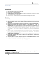
Specifications
Overview
The POUs are designed to be powered by either a single phase or a three phase AC input circuit. Three
phase units are available for either a Delta or WYE input connection.
Environmental
Temperature
Operating:
Storage:
10°C (50°F) min
-25°C (-13°F) min
45°C (113°F) max
65°C (149°F) max
Humidity
Operating:
Storage:
5% min
5% min
95% max
95% max
(non-condensing)
(non-condensing)
Elevation
Operating:
Storage:
0 m (0 ft) min
0 m (0 ft) min
2000 m (6561 ft) max
15240 m (50000 ft) max
Electrical
See nameplate for unit ratings.
Receptacle Ratings
NEMA 5-15R or L5-15R
125 Volts, 15 Amp
NEMA 5-20R or L5-20R
125 Volts, 20 Amp
NEMA 6-20R or L6-20R
250 Volts, 20 Amp
IEC-320 C13
125/250 Volt, 15 Amp (per Receptacle Bank)
IEC-320 C19
125/250 Volt, 20 Amp
Networking
Protocols
HTTP, ICMP, DHCP, TCP/IP, FTP
Ethernet Link Speed
10 Mbit; half-duplex
4
Version 1.0
Networked POU
Data Formats
HTML, SNMP, XML
EMC Verification
This Class A device complies with part 15 of the FCC Rules. Operation is subject to the following two
conditions: (1) This device may not cause harmful interference, and (2) this device must accept any
interference received, including interference that may cause undesired operation.
This Class A digital apparatus complies with Canadian ICES-003.
Cet appareil numérique de la classe A est conforme à la norme NMB-003 du Canada.
Warning: Changes or modifications to this unit not expressly approved by the party
responsible for compliance could void the user’s authority to operate this equipment.
FCC and Canadian ICES-003 requirements for units with Current Monitoring (EM) Meter: The ferrite core
shipped with the unit must be placed around the Ethernet cable close to the POU.
Version 1.0
5
Networked POU
Installation
Instructions
1. Using appropriate hardware, mount POU to rack.
1
2. Plug POU into de-energized receptacle .
3. Connect devices into POU’s output receptacles. Panduit recommends that the devices are turned
off until all devices are connected to POU.
4. Turn on branch circuit to energize POU.
5. Power on devices. Sequential power up is recommended to avoid high inrush current.
Guidelines
•
•
•
•
•
•
•
•
•
•
•
If the POU is installed in a cabinet the ambient temperature of the rack should be no greater than
45°C.
Install the POU such that the amount of airflow required for safe operation of equipment is not
compromised.
Mount the POU so that a hazardous condition is not achieved due to uneven mechanical loading.
Follow nameplate ratings when connecting equipment to the branch circuit. Take into
consideration the effect that overloading of the circuits might have on over-current protection and
supply wiring.
The POU relies on the building installation for protection from over-current conditions. A certified
overcurrent protection device is required in the building installation. The overcurrent protection
device should be sized according to the POU’s nameplate ratings and local/national electrical
codes.
Reliable earthing of rack-mount equipment should be maintained. Particular attention should be
given to supply connections other than direct connections to the branch circuit. The POU must
be connected to an earthed socket-outlet.
The POU is intended for Restricted Access Locations only and only qualified service personnel
should install and access the POU.
For pluggable equipment, install the POU so that the input plug or appliance coupler may be
disconnected for service.
Sequential power-up of devices powered by the POU is recommended to avoid high inrush
current.
Caution: Disconnect all power cords before servicing.
The POU is intended for use with TN, TT, or IT power supply systems
1
Branch Circuit should be sized based on the POU’s nameplate electrical rating. For example a 24 Amp
rated PDU is intended for use on a 30 Amp Branch Circuit. For Global Units a 32 Amp rated PDU is
intended for use on a 32 Amp Branch Circuit.
6
Version 1.0
Networked POU
Mounting
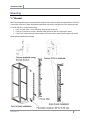
"L" Bracket
Affix Power Strip Mounting mounting brackets using #12-24 screws provided into tapped holes in the front
or the sides of the post. Power Strip Mounting Brackets can also be mounted to the rear equipment rails.
To center the 66.25” vertical power strips:
• For 7 foot post racks - mount L-Bracket at RU spaces 03 and 43
• For 8 foot 4 post racks, mount L-Bracket at RU spaces 06 and 46 or spaces 07 and 47
• For 6.5 foot 4 post racks, flip bottom bracket 180° and mount L-bracket at RU spaces 02 and 40
Mount power strip between brackets.
Version 1.0
7
Networked POU
Toolless Mounting Hardware
Use toolless buttons with key-holed slots built into cabinet or with optional key-holed brackets.
8
Version 1.0
Networked POU
Panduit Cabinet CS3
Version 1.0
9
Networked POU
Networked Monitoring
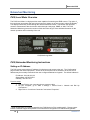
PViQ Local Meter Overview
The PViQ Local Meter is a high precision meter capable of measuring true RMS current. The value of
2
line current per input phase and output circuit current is shown on an easy to read, 4-digit LED Display.
The display continuously scrolls through the different measured values. The Monitor also provides
access to measurement data and control values through a web page, SNMP, or XML. The PViQ
Networked Monitoring Instructions section of this document will give more detailed information on the
network operation and functionality of the unit.
PViQ Monitoring Meter
PViQ Networked Monitoring Instructions
Setting an IP Address
The POU comes preset with an IP address for initial setup and access to the unit. The ‘Configuration’
page contains the network properties. Access to the unit requires the IP address to be known, the IP
address may be manually reset should the user-configured address be forgotten. The default address is:
IP Address: 192.168.123.123
Subnet Mask: 255.255.255.0
Gateway: 192.168.123.1
First time setup:
1. Connect POU to your computer using a crossover cable.
2. On your computer, go to “Start > Settings > Control Panel > Network and Dial Up
Connections.”
3. Right Click on “Local Area Connection” and select “Properties.”
2
Actual configuration of circuits measured by the PViQ Monitor is POU model specific. Please contact
Panduit Technical Support with questions on measurement configuration of PViQ Monitoring Meters.
10
Version 1.0
Networked POU
4. Select the option to “Use the following IP address” and enter:
IP address: 192.168.123.1
Subnet mask: 255.255.255.0
Default gateway: 192.168.123.1
3
Click “OK” twice.
You can now access the unit using your web browser at the permanent IP address of 192.168.123.1.
Typical Network Card Settings for PC
or Laptop to connect to default IP address
3
In some configurations, leaving the gateway field blank may resolve connectivity issues.
Version 1.0
11
Networked POU
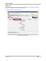
Accessing the POU Web GUI
Once you have properly set the IP Address for a unit, you can connect to the unit through a Web GUI.
The Panduit POU Web GUI consists of five tabs:
Current Monitoring
Display
Alarms
Configuration
XML | MIB
•
•
•
•
•
Current Monitoring tab
The Current Monitoring tab is the default tab. It displays the Total Amps usage for each circuit. A sample
of the Current Monitoring tab is shown below.
Current Monitoring tab using the Web GUI
12
Version 1.0
Networked POU
Display tab
The Display tab allows you to enter user friendly names for the POU, the Unit Location, and an Admin
Contact. You can also enter individual names for each circuit.
A sample of the Display tab screen is shown below.
Display tab using the Web GUI
Version 1.0
13
Networked POU
Alarms tab
The Alarms tab provides a current count of the number of warnings and alarms generated for the unit.
Individual warning and alarm counts are displayed for each circuit.
A sample of the Alarms tab screen is shown below.
Alarms tab using the Web GUI
14
Version 1.0
Networked POU
Configuration tab
The Configuration tab provides access to various Network and SNMP settings for the unit.
A sample of the Configuration tab is shown below.
Configuration tab using a web browser
Version 1.0
15
Networked POU
LED Display
Each POU has a built-in 4-digit LED display mounted midway down the chassis. The display scrolls
through the most recent current measurement (in amps) for each circuit, one at a time. It displays a
circuit name, pauses, and then displays the measurement. Momentarily press the “Pause Scroll/IP
Address Reset” button on the front of the POU to pause the display on the current measurement. While
paused, the display will cycle back and forth between circuit name and current reading every three
seconds. Momentarily pressing the “Pause Scroll/IP Address Reset” button again will skip ahead to the
next circuit. The display will begin to scroll again thirty seconds after the last button push.
During the first cycle after the display has been paused, the display may take up to six seconds to
display a measurement.
Due to the time required to measure current accurately, the same reading may be shown twice while
the display is paused.
For reference: Cr-1 = Circuit 1
Ph-A = Phase A
Cr-2 = Circuit 2
Ph-b = Phase B
Cr-3 = Circuit 3
Ph-C = Phase C
Cr-4 = Circuit 4
nEUt = Neutral
Cr-5 = Circuit 5
Fd-A = Feed A
Cr-6 = Circuit 6
Fd-B = Feed B
Viewing the IP Address/Resetting to Default IP
In the event that the IP address of the POU is lost, it is possible to view the currently configured IP
address on the unit’s built-in LED display or reset the IP address to the default.
To view the IP address, press and hold the “Pause Scroll/IP Address Reset” button on the front of the
POU for 20 seconds. The screen will stop displaying scrolling power data in order to display the currently
configured IP address. The display will show the IP address using the following format:
c-IPaaa.bbb.ccc.ddd
The ‘’ indicates a pause and the aaa/bbb/ccc/ddd indicate a portion of the currently configured IP
address. The IP address will be displayed twice before normal scrolling continues.
CAUTION:
If the “Pause Scroll/IP Address Reset” button is being held while the second
segment (bbb above) of the IP address is being displayed, the unit’s IP address will be reset.
To prevent this, release the button as soon as “c-IP” shows up on the display.
To reset the IP address to the backup IP address, press and hold the “Pause Scroll/IP Address Reset”
button on the front of the POU for 20 seconds, at which point the display will show the current IP address.
Continue to hold the “Pause Scroll/IP Address Reset” button for 10 more seconds and the display will
switch to scrolling d-IP192.168.123.123. The IP address is then reset to 192.168.123.123.
The display will resume its normal function after the display shows the IP address twice and the “Pause
16
Version 1.0
Networked POU
Scroll/IP Address Reset” has been released. Once the IP address has been reset, the Setting an IP
Address instructions should be followed to access the unit.
Rebooting the Meter
Should an Current Monitoring Meter with firmware version 1.36 or higher installed stop responding to
network traffic, it is possible to restore functionality by rebooting the meter without removing power from
the POU it is enclosed in.
To reboot the meter, press and hold the “Pause Scroll/IP Address Reset” button on the front on the POU
for 20 seconds. The screen will stop displaying scrolling power data in order to display the currently
configured IP address. The display will show the IP address using the following format:
c-IPaaa.bbb.ccc.ddd
The ‘’ indicates a pause and the aaa/bbb/ccc/ddd indicate a portion of the currently configured IP
address. As soon as “c-IP” is displayed, release the “Pause Scroll/IP Address Reset” button. Press and
release the “Pause Scroll/IP Address Reset” button twice while the IP address is being displayed. The
screen will read “8.8.8.8.” for a few seconds and then resume scrolling normally, indicating a successful
reboot.
Web Page
The main interface to the POU is its web page, accessible by typing the unit’s IP address into a web
browser. The web page is the source for the most up to date measurement of each circuit. All
measurements are in Amps.
SNMP/XML
In addition to HTML based web pages, the POU presents its data via SNMP and an XML page.
To use the POU with SNMP Client software, download the MIB from the link on the unit’s web page and
import it into the SNMP software. Contact the client software manufacturer for instructions specific to
their software. The POU’s SNMP community comes preset to ‘public’. To change this, go to the
‘Configuration’ page, enter a new name in the SNMP Community box and hit “Save Changes.” In
addition SNMP traps can be utilized to monitor a user set threshold for each circuit, alarm settings and
SNMP server settings are located on the ‘Configuration’ page.
The XML page provides terse output that is easily parsed by both humans and computers and is useful
for creating scripts to download and process information off the unit automatically. The XML page is
available at http://<IP address of meter>/data.xml.
Sample uses of XML and SNMP data are provided in the Sample Usage section of this document.
Version 1.0
17
Networked POU
Sample Usage
The simplest way to get data from a Current Monitoring Meter into a script is via the XML page. Simply
performing an HTTP GET (as a web browser does) on http://<IP address of meter>/data.xml will
download the XML file. The following examples assume that the meter’s IP address is 192.168.123.123.
Perl Example:
using LWP::UserAgent;
my $ip = "192.168.123.123";
my $browser = LWP::UserAgent->new;
$browser->timeout(5);
my $xmlFile = $browser->get("http://" . $ip . "/data.xml" )->content;
At this point, $xmlFile will contain the text of data.xml, ready to be parsed however necessary.
Unix/Linux Command Line Example:
wget http://192.168.123.123/data.xml
This command will download data.xml into the current directory. At this point, the file is ready to be used
by any local application or script.
18
Version 1.0
Networked POU
Service and Technical Support
Service
No service or maintenance is required. Do not attempt to open the POU or you may void the warranty.
No serviceable parts inside. Panduit recommends that power be removed from the unit before installing
or removing any equipment.
Technical Support
For Technical Support on the PViQ POU please contact Panduit Technical Support using one of the
following methods:
•
•
1-800-777-3300 (toll-free)
[email protected]
Version 1.0
19