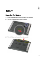
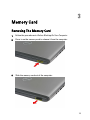
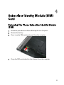
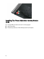
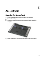
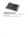
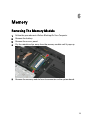
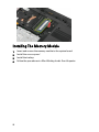
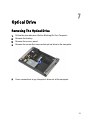
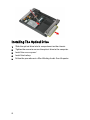
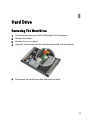
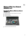
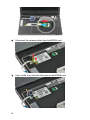
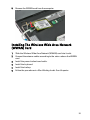
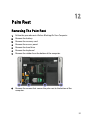
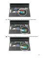
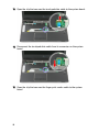
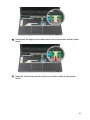
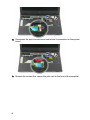
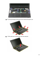
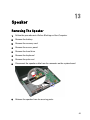
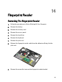
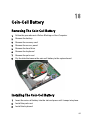
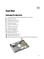
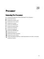
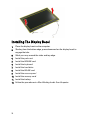
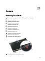
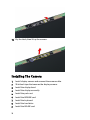
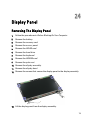
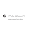
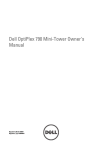
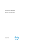
1
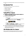
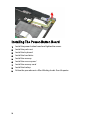
Dell Vostro 3350
Owner's Manual
Regulatory Model P13S
Regulatory Type P13S001
Notes, Cautions, and Warnings
NOTE: A NOTE indicates important information that helps you make better use of your
computer.
CAUTION: A CAUTION indicates potential damage to hardware or loss of data if
instructions are not followed.
WARNING: A WARNING indicates a potential for property damage, personal injury, or
death.
Information in this publication is subject to change without notice.
© 2011 Dell Inc. All rights reserved.
Reproduction of these materials in any manner whatsoever without the written permission of Dell Inc. is
strictly forbidden.
Trademarks used in this text: Dell™, the DELL logo, Dell Precision™, Precision ON™,ExpressCharge™,
Latitude™, Latitude ON™, OptiPlex™, Vostro™, and Wi-Fi Catcher™ are trademarks of Dell Inc. Intel®,
Pentium®, Xeon®, Core™, Atom™, Centrino®, and Celeron® are registered trademarks or trademarks of Intel
Corporation in the U.S. and other countries. AMD® is a registered trademark and AMD Opteron™,
AMD Phenom™, AMD Sempron™, AMD Athlon™, ATI Radeon™, and ATI FirePro™ are trademarks of
Advanced Micro Devices, Inc. Microsoft®, Windows®, MS-DOS®, Windows Vista®, the Windows Vista start
button, and Office Outlook® are either trademarks or registered trademarks of Microsoft Corporation in the
United States and/or other countries. Blu-ray Disc™ is a trademark owned by the Blu-ray Disc Association
(BDA) and licensed for use on discs and players. The Bluetooth® word mark is a registered trademark and
owned by the Bluetooth® SIG, Inc. and any use of such mark by Dell Inc. is under license. Wi-Fi® is a
registered trademark of Wireless Ethernet Compatibility Alliance, Inc.
Other trademarks and trade names may be used in this publication to refer to either the entities claiming the
marks and names or their products, Dell Inc. disclaims any proprietary interest in trademarks and trade
names other than its own.
2011 – 06
Rev. A00
Contents
Notes, Cautions, and Warnings..................................................................2
1 Working on Your Computer......................................................................7
Before Working Inside Your Computer.............................................................................7
Recommended Tools.........................................................................................................9
Turning Off Your Computer................................................................................................9
After Working Inside Your Computer................................................................................9
2 Battery........................................................................................................11
Removing The Battery.....................................................................................................11
Installing The Battery......................................................................................................12
3 Memory Card............................................................................................13
Removing The Memory Card...........................................................................................13
Installing The Memory Card............................................................................................14
4 Subscriber Identity Module (SIM) Card...............................................15
Removing The Phone Subscriber Identity Module (SIM)................................................15
Installing The Phone Subscriber Identity Module (SIM).................................................16
5 Access Panel............................................................................................17
Removing The Access Panel...........................................................................................17
Installing The Access Panel............................................................................................18
6 Memory......................................................................................................19
Removing The Memory Module......................................................................................19
Installing The Memory Module.......................................................................................20
7 Optical Drive..............................................................................................21
Removing The Optical Drive............................................................................................21
Installing The Optical Drive.............................................................................................22
8 Hard Drive..................................................................................................23
Removing The Hard Drive................................................................................................23
Installing The Hard Drive.................................................................................................26
9 Wireless Local Area Network (WLAN) Card.......................................27
Removing Wireless Local Area Network (WLAN) Card..................................................27
Installing The Wireless Local Area Network (WLAN) Card............................................28
10 Keyboard..................................................................................................29
Removing The Keyboard.................................................................................................29
Installing The Keyboard..................................................................................................31
11 Wireless Wide Area Network (WWAN) Card...................................33
Removing The Wireless Wide Area Network (WWAN) Card.........................................33
Installing The Wireless Wide Area Network (WWAN) Card..........................................35
12 Palm Rest.................................................................................................37
Removing The Palm Rest.................................................................................................37
Installing The Palm Rest..................................................................................................44
13 Speaker....................................................................................................45
Removing The Speaker...................................................................................................45
Installing The Speaker.....................................................................................................46
14 Fingerprint Reader.................................................................................49
Removing The Fingerprint Reader...................................................................................49
Installing The Fingerprint Reader....................................................................................51
15 LED Board................................................................................................53
Removing The LED Board................................................................................................53
Installing The LED Board.................................................................................................54
16 Power-Button Board..............................................................................55
Removing The Power-Button Board...............................................................................55
Installing The Power-Button Board................................................................................56
17 Quick Launch Button Board.................................................................57
Removing The Quick Launch Button Board....................................................................57
Installing The Quick Launch Button Board.....................................................................58
18 Coin-Cell Battery....................................................................................61
Removing The Coin-Cell Battery.....................................................................................61
Installing The Coin-Cell Battery.......................................................................................61
19 Heat Sink..................................................................................................63
Removing The Heat Sink.................................................................................................63
Installing The Heat Sink..................................................................................................64
20 Processor................................................................................................65
Removing The Processor................................................................................................65
Installing The Processor.................................................................................................66
21 Display Assembly...................................................................................69
Removing The Display Assembly....................................................................................69
Installing The Display Assembly.....................................................................................71
22 Display Bezel...........................................................................................73
Removing The Display Bezel...........................................................................................73
Installing The Display Bezel............................................................................................74
23 Camera.....................................................................................................75
Removing The Camera....................................................................................................75
Installing The Camera.....................................................................................................76
24 Display Panel..........................................................................................79
Removing The Display Panel...........................................................................................79
Installing The Display Panel............................................................................................81
25 Display Brackets and Hinges...............................................................83
Removing Display Brackets And Hinges.........................................................................83
Installing The Display Brackets And Hinges...................................................................85
26 Display Cable..........................................................................................87
Removing The Display Cable...........................................................................................87
Installing The Display Cable............................................................................................88
27 System Board..........................................................................................89
Removing The System Board..........................................................................................89
Installing The System Board...........................................................................................91
28 Input/Output Board................................................................................93
Removing The Input/Output (I/O) Board..........................................................................93
Installing The Input/Output Board...................................................................................94
29 System Setup..........................................................................................95
System Setup Overview..................................................................................................95
System Setup Enter.........................................................................................................95
System Setup Screens....................................................................................................96
System Setup Options.....................................................................................................97
30 Diagnostics............................................................................................101
Device Status Lights......................................................................................................101
Battery Status Lights.....................................................................................................101
Diagnostic Beep Codes.................................................................................................101
31 Specifications.......................................................................................103
32 Contacting Dell.....................................................................................113
Contacting Dell..............................................................................................................113
Working on Your Computer
1
Before Working Inside Your Computer
Use the following safety guidelines to help protect your computer from potential
damage and to help to ensure your personal safety. Unless otherwise noted,
each procedure included in this document assumes that the following
conditions exist:
•
•
•
You have performed the steps in Working on Your Computer.
You have read the safety information that shipped with your computer.
A component can be replaced or--if purchased separately--installed by
performing the removal procedure in reverse order.
WARNING: Before working inside your computer, read the safety information that
shipped with your computer. For additional safety best practices information, see
the Regulatory Compliance Homepage at www.dell.com/regulatory_compliance.
CAUTION: Many repairs may only be done by a certified service technician. You
should only perform troubleshooting and simple repairs as authorized in your
product documentation, or as directed by the online or telephone service and
support team. Damage due to servicing that is not authorized by Dell is not covered
by your warranty. Read and follow the safety instructions that came with the
product.
CAUTION: To avoid electrostatic discharge, ground yourself by using a wrist
grounding strap or by periodically touching an unpainted metal surface, such as a
connector on the back of the computer.
CAUTION: Handle components and cards with care. Do not touch the components
or contacts on a card. Hold a card by its edges or by its metal mounting bracket.
Hold a component such as a processor by its edges, not by its pins.
7
CAUTION: When you disconnect a cable, pull on its connector or on its pull-tab, not
on the cable itself. Some cables have connectors with locking tabs; if you are
disconnecting this type of cable, press in on the locking tabs before you disconnect
the cable. As you pull connectors apart, keep them evenly aligned to avoid bending
any connector pins. Also, before you connect a cable, ensure that both connectors
are correctly oriented and aligned.
NOTE: The color of your computer and certain components may appear differently
than shown in this document.
To avoid damaging your computer, perform the following steps before you begin
working inside the computer.
1.
Ensure that your work surface is flat and clean to prevent the computer
cover from being scratched.
2.
Turn off your computer (see Turning Off Your Computer).
3.
If the computer is connected to a docking device (docked) such as the
optional Media Base or Battery Slice, undock it.
CAUTION: To disconnect a network cable, first unplug the cable from your
computer and then unplug the cable from the network device.
4.
Disconnect all network cables from the computer.
5.
Disconnect your computer and all attached devices from their electrical
outlets.
6.
Close the display and turn the computer upside-down on a flat work
surface.
NOTE: To avoid damaging the system board, you must remove the main battery
before you service the computer.
7.
Remove the main battery.
8.
Turn the computer top-side up.
9.
Open the display.
10. Press the power button to ground the system board.
CAUTION: To guard against electrical shock, always unplug your computer from the
electrical outlet before opening the display.
CAUTION: Before touching anything inside your computer, ground yourself by
touching an unpainted metal surface, such as the metal at the back of the
computer. While you work, periodically touch an unpainted metal surface to
dissipate static electricity, which could harm internal components.
8
11. Remove any installed ExpressCards or Smart Cards from the appropriate
slots.
Recommended Tools
The procedures in this document may require the following tools:
•
•
•
•
•
Small flat-blade screwdriver
#0 Phillips screwdriver
#1 Phillips screwdriver
Small plastic scribe
Flash BIOS update program CD
Turning Off Your Computer
CAUTION: To avoid losing data, save and close all open files and exit all open
programs before you turn off your computer.
1.
Shut down the operating system:
•
In Windows Vista :
Click Start
, then click the arrow in the lower-right corner of the
Start menu as shown below, and then click Shut Down.
•
2.
In Windows XP:
Click Start → Turn Off Computer → Turn Off . The computer turns off
after the operating system shutdown process is complete.
Ensure that the computer and all attached devices are turned off. If your
computer and attached devices did not automatically turn off when you
shut down your operating system, press and hold the power button for
about 4 seconds to turn them off.
After Working Inside Your Computer
After you complete any replacement procedure, ensure you connect any
external devices, cards, and cables before turning on your computer.
9
CAUTION: To avoid damage to the computer, use only the battery designed for this
particular Dell computer. Do not use batteries designed for other Dell computers.
1.
2.
Connect any external devices, such as a port replicator, battery slice, or
media base, and replace any cards, such as an ExpressCard.
Connect any telephone or network cables to your computer.
CAUTION: To connect a network cable, first plug the cable into the network device
and then plug it into the computer.
3.
4.
5.
10
Replace the battery.
Connect your computer and all attached devices to their electrical outlets.
Turn on your computer.
Battery
2
Removing The Battery
1.
Follow the procedures in Before Working On Your Computer.
2.
Slide the release latches to unlock the battery.
3.
Slide the battery and remove it from the computer.
11
Installing The Battery
1.
2.
12
Slide the battery into its slot until it clicks into place.
Follow the procedures in After Working Inside Your Computer.
Memory Card
3
Removing The Memory Card
1.
Follow the procedures in Before Working On Your Computer.
2.
Press in on the memory card to release it from the computer.
3.
Slide the memory card out of the computer.
13
Installing The Memory Card
1.
2.
14
Push the memory card into the compartment until it snaps into place.
Follow the procedures in After Working Inside Your Computer.
Subscriber Identity Module (SIM)
Card
4
Removing The Phone Subscriber Identity Module
(SIM)
1.
2.
3.
Follow the procedures in Before Working On Your Computer.
Remove the battery.
Press in on the SIM card to release it from the computer.
4.
Grasp the SIM card and pull out to release it from the computer.
15
Installing The Phone Subscriber Identity Module
(SIM)
1.
2.
3.
16
Push the SIM card into the slot until it is fully engaged.
Install the battery.
Follow the procedures in After Working Inside Your Computer.
Access Panel
5
Removing The Access Panel
1.
2.
3.
Follow the procedures in Before Working On Your Computer.
Remove the battery.
Remove the screws that secures the access panel to the base of the
computer.
4.
Lift the access panel up at an angle and remove it from the computer.
17
Installing The Access Panel
1.
2.
3.
18
Tighten the screws to secure the access panel to the base of the computer.
Install the battery.
Follow the procedures in After Working Inside Your Computer.
Memory
6
Removing The Memory Module
1.
2.
3.
4.
Follow the procedures in Before Working On Your Computer
Remove the battery.
Remove the access panel.
Pry the retention clips away from the memory module until it pops up.
5.
Remove the memory module from its connector on the system board.
19
Installing The Memory Module
1.
2.
3.
4.
20
Insert and secure the memory module to the system board.
Install the access panel.
Install the battery.
Follow the procedures in After Working Inside Your Computer.
Optical Drive
7
Removing The Optical Drive
1.
2.
3.
4.
Follow the procedures in Before Working On Your Computer.
Remove the battery.
Remove the access panel.
Remove the screw that secures the optical drive to the computer.
5.
Use a screwdriver to pry the optical drive out of the computer.
21
Installing The Optical Drive
1.
2.
3.
4.
5.
22
Slide the optical drive into its compartment on the chassis.
Tighten the screw to secure the optical drive to the computer.
Install the access panel.
Install the battery.
Follow the procedures in After Working Inside Your Computer.
Hard Drive
8
Removing The Hard Drive
1.
2.
3.
4.
Follow the procedures in Before Working On Your Computer.
Remove the battery.
Remove the access panel.
Open the clip that secures the hard-drive assembly to the computer.
5.
Disconnect the hard-drive cable from the hard drive.
23
6.
Remove the screws that secure the hard-drive assembly to the computer.
7.
Lift the hard drive up at an angle from the system and remove it from the
computer.
24
8.
Remove the screws that secure the hard-drive bracket to the hard drive.
9.
Lift the hard-drive bracket up and away from the hard drive.
25
10. Remove the hard drive board from the hard drive.
Installing The Hard Drive
1.
2.
3.
4.
5.
6.
7.
8.
26
Install the screws to secure the hard drive board to the hard drive.
Place the hard drive in its compartment .
Replace the screws to secure the hard drive to the system.
Connect the hard drive cable to the system board.
Replace the hard drive cable securing clip.
Install the access panel.
Install the battery.
Follow the procedures in After Working Inside Your Computer.
Wireless Local Area Network
(WLAN) Card
9
Removing Wireless Local Area Network (WLAN)
Card
1.
2.
3.
4.
Follow the procedures in Before Working On Your Computer.
Remove the battery.
Remove the access panel.
Disconnect the antenna cables from the WLAN card.
5.
Use a scribe to pry the latch to release the WLAN card.
27
6.
Remove the WLAN card from the computer.
Installing The Wireless Local Area Network
(WLAN) Card
1.
Slide the WLAN card into its slot.
2.
Connect the antenna cables according to the color code on the WLAN
card.
3.
Install the access panel.
4.
Install the battery.
5.
Follow the procedures in After Working Inside Your Computer.
28
Keyboard
10
Removing The Keyboard
1.
2.
3.
Follow the procedures in Before Working On Your Computer.
Remove the battery.
Using a small plastic scribe, release the four latches that secures the
keyboard to the computer.
4.
Flip the keyboard over and lay it on the palm rest.
29
5.
Open the clip to release the keyboard cable.
6.
Disconnect the keyboard cable from its connector on the system board.
30
7.
If your computer comes with a backlit keyboard, disconnect the keyboard
backlight cable.
8.
Remove the keyboard from the computer.
Installing The Keyboard
1.
2.
3.
Connect the keyboard data cable to the system board.
Install the battery.
Follow the procedures in After Working Inside Your Computer.
31
32
Wireless Wide Area Network
(WWAN) Card
11
Removing The Wireless Wide Area Network
(WWAN) Card
1.
2.
3.
4.
Follow the procedures in Before Working On Your Computer.
Remove the battery.
Remove the keyboard
Open the power button board cable securing clip.
5.
Disconnect the power button board cable.
33
6.
Disconnect the antenna cables from the WWAN card.
7.
Use a scribe to pry the latch that secures the WWAN card.
34
8.
Remove the WWAN card from the computer.
Installing The Wireless Wide Area Network
(WWAN) Card
1.
2.
3.
4.
5.
6.
Slide the Wireless Wide Area Network (WWAN) card into its slot.
Connect the antenna cables according to the color code on the WWAN
card.
Install the power button board cable.
Install the keyboard.
Install the battery.
Follow the procedures in After Working Inside Your Computer.
35
36
Palm Rest
12
Removing The Palm Rest
1.
2.
3.
4.
5.
6.
7.
Follow the procedures in Before Working On Your Computer.
Remove the battery.
Remove the memory card.
Remove the access panel.
Remove the hard drive.
Remove the keyboard.
Remove the rubber from the bottom of the computer.
8.
Remove the screws that secure the palm rest to the bottom of the
computer.
37
9.
Open the clip that secures the power-button board cable to the system
board.
10. Disconnect the power-button board cable from its connector on the system
board.
38
11. Open the clip that secures the LED board cable to the system board.
12. Disconnect the LED board cable from its connector on the system board.
39
13. Open the clip that secures the touchpad data cable to the system board.
14. Disconnect the touchpad data cable from its connector on the system
board.
15. Open the clip that secures the finger print reader cable to the system
board.
40
16. Disconnect the finger print reader cable from its connector on the system
board.
17. Open the clip that secures the quick launch board cable to the system
board.
41
18. Disconnect the quick launch board cable from its connector on the system
board.
19. Remove the screws that secure the palm rest to the front of the computer.
42
20. Pry along the edges of the palm rest to release the palm rest.
21. Lift the palm rest up and away from the computer.
43
Installing The Palm Rest
1.
2.
3.
4.
5.
6.
Starting from the right edge of the palm rest, press downwards on the
computer to engage the tabs.
Work your way around the edges and ensure the tabs are fully engaged.
Connect all cables to the system board.
Tighten the screws to secure the palm rest.
Tighten the screws on the bottom of the computer to secure the palm rest.
Install the keyboard.
7.
8.
9.
10.
11.
Install the hard drive.
Install the access panel.
Install the memory card.
Install the battery
Follow the procedures in After Working Inside Your Computer.
44
Speaker
13
Removing The Speaker
1.
Follow the procedures in Before Working on Your Computer.
2.
Remove the battery.
3.
Remove the memory card.
4.
Remove the access panel.
5.
Remove the hard drive.
6.
Remove the keyboard.
7.
Remove the palm rest.
8.
Disconnect the speaker cable from its connector on the system board.
9.
Release the speaker from its securing posts.
45
10. Release the speaker cable from the routing channel.
11. Lift the speakers up and away from the computer.
Installing The Speaker
1.
Install the speaker cable in the routing channel.
2.
Install the speaker to its securing posts.
3.
Connect the speaker cable.
4.
Install the palm rest.
5.
Install the keyboard.
6.
Install the hard drive.
7.
Install the access panel.
8.
Install the memory card
46
9. Install the battery.
10. Follow the procedures in After Working Inside Your Computer.
47
48
Fingerprint Reader
14
Removing The Fingerprint Reader
1.
Follow the procedures in Before Working On Your Computer.
2.
Remove the battery.
3.
Remove the memory card.
4.
Remove the access panel.
5.
Remove the hard drive.
6.
Remove the keyboard.
7.
Remove the palm rest.
8.
Release the fingerprint reader cable from the adhesive affixing it to the
palm rest.
9.
Remove the screw that secures the fingerprint reader bracket.
49
10. Lift up the fingerprint reader bracket at an angle and remove it from the
computer.
11. Lift up the fingerprint reader board and remove.
50
Installing The Fingerprint Reader
1.
2.
3.
4.
5.
Install the fingerprint reader board and the bracket.
Tighten the screws that secure the fingerprint reader bracket.
Affix the finger print reader cable to the palm rest.
Install the palm rest.
Install the keyboard.
6. Install the hard drive
7. Install the access panel.
8. Install the memory card.
9. Install the battery.
10. Follow the procedures in After Working Inside Your Computer.
51
52
LED Board
15
Removing The LED Board
1.
Follow the procedures in Before Working On Your Computer.
2.
Remove the battery.
3.
Remove the memory card.
4.
Remove the access panel.
5.
Remove the hard drive.
6.
Remove the keyboard.
7.
Remove the palm rest.
8.
Peel open the tape that secures the LED board cable.
9.
Pry the latches that secure the LED board; then lift up and remove the LED
board from the computer.
53
Installing The LED Board
1.
2.
3.
4.
5.
Secure the latches to the LED board.
Affix the tape to secure the LED board cable.
Install the palm rest.
Install the keyboard.
Install the hard drive
6.
7.
8.
9.
Install the access panel.
Install the memory card.
Install the battery.
Follow the procedures in After Working Inside Your Computer.
54
Power-Button Board
16
Removing The Power-Button Board
1.
Follow the procedures in Before Working On Your Computer.
2.
Remove the battery.
3.
Remove the memory card.
4.
Remove the access panel.
5.
Remove the memory.
6.
Remove the hard drive.
7.
Remove the keyboard.
8.
Remove the palm rest.
9.
Remove the screw that secures the power-button board.
10. Pry the latch to release the power-button board; then lift up and remove it
from the computer.
55
Installing The Power-Button Board
1.
2.
3.
4.
5.
6.
7.
8.
9.
56
Install the power-button board and tighten the screw.
Install the palm rest.
Install the keyboard.
Install the hard drive
Install the memory.
Install the access panel.
Install the memory card.
Install the battery.
Follow the procedures in After Working Inside Your Computer.
Quick Launch Button Board
17
Removing The Quick Launch Button Board
1.
Follow the procedures in Before Working On Your Computer.
2.
Remove the battery.
3.
Remove the memory card.
4.
Remove the access panel.
5.
Remove the memory.
6.
Remove the hard drive.
7.
Remove the keyboard.
8.
Remove the palm rest.
9.
Release the quick launch button board cable from the adhesive affixing it to
the palm rest.
10. Remove the screw that secures the quick launch button board.
57
11. Pry the latches to release the quick launch button board; then lift up and
remove it from the computer.
Installing The Quick Launch Button Board
1.
Install the quick launch button board and tighten the screw.
2.
Affix the quick launch button board cable to the palm rest.
3.
Install the palm rest.
4.
Install the keyboard.
5.
Install the hard drive
6.
Install the memory.
7.
Install the access panel.
8.
Install the memory card.
58
9. Install the battery.
10. Follow the procedures in After Working Inside Your Computer.
59
60
Coin-Cell Battery
18
Removing The Coin-Cell Battery
1.
Follow the procedures in Before Working on Your Computer.
2.
Remove the battery.
3.
Remove the memory card.
4.
Remove the access panel.
5.
Remove the hard drive.
6.
Remove the keyboard.
7.
Remove the palm rest.
8.
Pry the tabs that secure the coin-cell battery to the system board.
Installing The Coin-Cell Battery
1.
Insert the coin-cell battery into the slot and press until it snaps into place.
2.
Install the palm rest.
3.
Install the keyboard.
61
4.
5.
6.
7.
Install the hard drive.
Install the access panel.
Install the memory card
Install the battery
8.
Follow the procedures in After Working Inside Your Computer.
62
Heat Sink
19
Removing The Heat Sink
1.
Follow the procedures in Before Working On Your Computer.
2.
Remove the battery.
3.
Remove the memory card.
4.
Remove the access panel.
5.
Remove the memory.
6.
Remove the WLAN card.
7.
Remove the optical drive.
8.
Remove the hard drive.
9.
Remove the keyboard.
10. Remove the WWAN card.
11. Remove the palm rest.
12. Remove the display assembly.
13. Remove the system board.
14. Lift the heat sink and fan assembly up and away from the system board.
63
Installing The Heat Sink
1.
2.
Install the heat sink in the slot.
Install the system board
3.
4.
5.
6.
7.
Install the display assembly.
Install the palm rest.
Install the WWAN card.
Install the keyboard.
Install the hard drive
8.
9.
10.
11.
12.
13.
14.
Install the optical drive.
Install the WLAN card.
Install the memory.
Install the access panel.
Install the memory card.
Install the battery.
Follow the procedures in After Working Inside Your Computer.
64
Processor
20
Removing The Processor
1.
2.
3.
4.
5.
6.
7.
8.
9.
10.
11.
12.
13.
14.
Follow the procedures in Before Working On Your Computer.
Remove the battery.
Remove the memory card.
Remove the access panel.
Remove the memory.
Remove the WLAN card.
Remove the optical drive.
Remove the hard drive.
Remove the keyboard.
Remove the WWAN card.
Remove the palm rest.
Remove the display assembly.
Remove the system board.
Using a flat-blade screwdriver, rotate the processor cam lock in a counterclockwise direction.
65
15. Lift the processor up and away from the system board.
Installing The Processor
1.
Insert the processor into the processor socket. Ensure the processor is
properly seated.
2.
Tighten the cam lock in a clockwise direction.
3.
Install the system board
4.
Install the display assembly.
5.
Install the palm rest.
6.
Install the WWAN card.
7.
Install the keyboard.
8.
Install the hard drive
66
9.
10.
11.
12.
13.
14.
15.
Install the optical drive.
Install the WLAN card.
Install the memory.
Install the access panel.
Install the memory card.
Install the battery.
Follow the procedures in After Working Inside Your Computer.
67
68
Display Assembly
21
Removing The Display Assembly
1.
Follow the procedures in Before Working On Your Computer.
2.
Remove the battery.
3.
Remove the memory card.
4.
Remove the access panel.
5.
Remove the WLAN card.
6.
Remove the hard drive.
7.
Remove the keyboard.
8.
Remove the WWAN card.
9.
Remove the palm rest.
10. Disconnect the antenna cables from the routing channel.
11. Pull out the antenna cables from the routing hole.
69
12. Disconnect the display cable from the system board.
13. Release the WWAN cables from the routing channel.
70
14. Remove the screws that secure the display assembly to the computer.
15. Lift the display assembly up from the computer, then forward and remove.
Installing The Display Assembly
1.
Attach the display assembly to the base of the computer.
2.
Tighten the screws to secure the display assembly.
3.
Secure the antenna cables to the routing channels.
4.
Connect display cable to system board.
5.
Connect antenna cables to installed wireless solutions.
6.
Install the palm rest.
7.
Install the WWAN card.
8.
Install the keyboard.
71
9.
10.
11.
12.
13.
14.
72
Install the hard drive.
Install the WLAN card.
Install the access panel.
Install the memory card.
Install the battery.
Follow the procedures in After Working Inside Your Computer.
Display Bezel
22
Removing The Display Bezel
1.
Follow the procedures in Before Working On Your Computer.
2.
Remove the battery.
3.
Remove the memory card.
4.
Remove the access panel.
5.
Remove the WLAN card.
6.
Remove the hard drive.
7.
Remove the keyboard.
8.
Remove the WWAN card.
9.
Remove the palm rest.
10. Remove the display assembly.
11. Using a plastic scribe, pry under the display bezel to release it from the
display assembly.
12. Lift the display bezel and remove it from the display assembly.
73
Installing The Display Bezel
1.
2.
Place the display bezel on the computer.
Starting from the bottom edge, press downward on the display bezel to
engage the tabs.
3. Work your way around the sides and top edge.
4. Install the palm rest.
5. Install the WWAN card.
6. Install the keyboard.
7. Install the hard drive.
8. Install the WLAN card.
9. Install the access panel.
10. Install the memory card.
11. Install the battery.
12. Follow the procedures in After Working Inside Your Computer.
74
Camera
23
Removing The Camera
1.
Follow the procedures in Before Working On Your Computer.
2.
Remove the battery.
3.
Remove the memory card.
4.
Remove the access panel.
5.
Remove the WLAN card.
6.
Remove the hard drive.
7.
Remove the keyboard.
8.
Remove the WWAN card.
9.
Remove the palm rest.
10. Remove the display assembly.
11. Remove the display bezel
12. Disconnect the camera cable.
13. Peel off tape that secures the camera.
75
14. Pry the latch; then lift up the camera.
Installing The Camera
1.
Install display camera and connect the camera cable.
2.
Stick back tape that secures the display camera..
3.
Install the display bezel.
4.
Install the display assembly.
5.
Install the palm rest.
6.
Install the WWAN card.
7.
Install the keyboard.
8.
Install the hard drive.
9.
Install the WLAN card.
76
10.
11.
12.
13.
Install the access panel.
Install the memory card.
Install the battery.
Follow the procedures in After Working Inside Your Computer.
77
78
Display Panel
24
Removing The Display Panel
1.
Follow the procedures in Before Working On Your Computer.
2.
Remove the battery.
3.
Remove the memory card.
4.
Remove the access panel.
5.
Remove the WLAN card.
6.
Remove the hard drive.
7.
Remove the keyboard.
8.
Remove the WWAN card.
9.
Remove the palm rest.
10. Remove the display assembly.
11. Remove the display bezel.
12. Remove the screws that secure the display panel to the display assembly.
13. Lift the display panel from the display assembly.
79
14. Remove the tape that secures the display cable to the display panel.
15. Disconnect the display panel cable from its connector on the panel.
80
Installing The Display Panel
1.
2.
3.
4.
5.
6.
7.
Install the display cable on the display panel.
Replace the tape to secure the display cable to the display panel.
Install the screws that secure the display panel to the display assembly.
Install the display bezel
Install the display assembly
Install the palm rest.
Install the WWAN card.
8.
9.
10.
11.
12.
13.
14.
Install the keyboard.
Install the hard drive.
Install the WLAN card.
Install the access panel.
Install the memory card.
Install the battery.
Follow the procedures in After Working Inside Your Computer.
81
82
Display Brackets and Hinges
25
Removing Display Brackets And Hinges
1.
Follow the procedures in Before Working On Your Computer.
2.
Remove the battery.
3.
Remove the memory card.
4.
Remove the access panel.
5.
Remove the WLAN card.
6.
Remove the hard drive.
7.
Remove the keyboard.
8.
Remove the WWAN card.
9.
Remove the palm rest.
10. Remove the display assembly.
11. Remove the display bezel.
12. Remove the display panel.
13. Remove the screws that secure the display brackets and hinges to the
display assembly.
83
14. Turn over the left display bracket and hinge.
15. Release the cables from the left hinge; then remove the left display bracket
and hinge.
16. Release the cables from the right hinge; then remove the right display
bracket and hinge.
84
Installing The Display Brackets And Hinges
1.
Install the display brackets and display hinges.
2.
Tighten the screws to secure the display brackets and hinges to the display
assembly.
3.
Route the cables into the right and left hinges.
4.
Install the display panel
5.
Install the display bezel
6.
Install the display assembly
7.
Install the palm rest.
8.
Install the WWAN card.
9.
Install the keyboard.
10. Install the hard drive.
11. Install the WLAN card.
12. Install the access panel.
13. Install the memory card.
14. Install the battery.
15. Follow the procedures in After Working Inside Your Computer.
85
86
Display Cable
26
Removing The Display Cable
1.
2.
3.
4.
5.
6.
7.
8.
9.
10.
11.
12.
13.
14.
Follow the procedures in Before Working On Your Computer.
Remove the battery.
Remove the memory card.
Remove the access panel.
Remove the WLAN card.
Remove the hard drive.
Remove the keyboard.
Remove the WWAN card.
Remove the palm rest.
Remove the display assembly.
Remove the display bezel.
Remove the display panel.
Remove the display brackets and hinges.
Peel the display cable from the adhesive affixing it to the display cover, and
remove it from the display assembly.
87
Installing The Display Cable
1.
Install the display cable affixing it to the display cover.
2.
Install the display brackets and hinges.
3.
Install the display panel.
4.
Install the display camera.
5.
Install the display bezel.
6.
Install the display assembly.
7.
Install the palm rest.
8.
Install the WWAN card.
9.
Install the keyboard.
10. Install the hard drive.
11. Install the WLAN card.
12. Install the access panel.
13. Install the memory card.
14. Install the battery.
15. Follow the procedures in After Working Inside Your Computer.
88
System Board
27
Removing The System Board
1.
Follow the procedures in Before Working On Your Computer.
2.
Remove the battery.
3.
Remove the memory card.
4.
Remove the access panel.
5.
Remove the memory.
6.
Remove the WLAN card.
7.
Remove the optical drive.
8.
Remove the hard drive.
9.
Remove the keyboard.
10. Remove the WWAN card.
11. Remove the palm rest.
12. Remove the display assembly.
13. Loosen the screws that secures the heat sink to the system board.
14. Disconnect the fan cable that secures the heatsink to the system board.
89
15. Remove the screws that secure the system board to the computer.
16. Lift the system board up and away from the computer.
90
Installing The System Board
1.
2.
3.
4.
5.
6.
Align the system board to the port connectors on the rear of the chassis
and place the system board in the computer.
Tighten the screws to secure the system board in place.
Replace the fan cable.
Tighten the screws to secure the heatsink to the system board.
Install the display assembly.
Install the palm rest.
7.
8.
9.
10.
11.
12.
13.
14.
15.
16.
Install the WWAN card.
Install the keyboard.
Install the hard drive.
Install the optical drive.
Install the WLAN card.
Install the memory.
Install the access panel.
Install the memory card.
Install the battery.
Follow the procedures in After Working Inside Your Computer.
91
92
Input/Output Board
28
Removing The Input/Output (I/O) Board
1.
Follow the procedures in Before Working On Your Computer.
2.
Remove the battery.
3.
Remove the memory card.
4.
Remove the access panel.
5.
Remove the WLAN card.
6.
Remove the optical drive
7.
Remove the hard drive.
8.
Remove the keyboard.
9.
Remove the WWAN card.
10. Remove the palm rest.
11. Remove the display assembly.
12. Remove the system board
13. Lift up the I/O board at an angle and remove it from the computer.
93
Installing The Input/Output Board
1.
2.
Install the Input/Output board into the slot.
Install the system board
3.
4.
5.
6.
7.
Install the display assembly.
Install the palm rest.
Install the WWAN card.
Install the keyboard.
Install the hard drive
8.
9.
10.
11.
12.
13.
14.
Install the optical drive.
Install the WLAN card.
Install the memory.
Install the access panel.
Install the memory card.
Install the battery.
Follow the procedures in After Working Inside Your Computer.
94
System Setup
29
System Setup Overview
System Setup allows you to:
•
•
•
change the system configuration information after you add, change, or
remove any hardware in your computer.
set or change a user-selectable option such as the user password.
read the current amount of memory or set the type of hard drive installed.
Before you use System Setup, it is recommended that you write down the
System Setup screen information for future reference.
CAUTION: Unless you are an expert computer user, do not change the settings for
this program. Certain changes can cause your computer to work incorrectly.
System Setup Enter
1.
2.
3.
Turn on (or restart) your computer.
When the blue DELL logo is displayed, you must watch for the F2 prompt to
appear.
Once the F2 prompt appears, press <F2> immediately.
NOTE: The F2 prompt indicates that the keyboard has initialized. This prompt can
appear very quickly, so you must watch for it to display, and then press <F2> . If you
press <F2> before you are prompted, this keystroke will be lost.
4.
If you wait too long and the operating system logo appears, continue to
wait until you see the Microsoft Windows desktop. Then, shut down your
computer and try again.
95
System Setup Screens
Menu — Appears on top of the System Setup window. This field provides a menu to
access the System Setup options. Press < Left Arrow > and < Right Arrow > keys to
navigate. As a Menu option is highlighted, the Options List lists the options that define
the hardware installed on your computer.
Options List — Appears on
the left side of the System
Setup window. The field
lists features that define the
configuration of your
computer, including
installed hardware, power
conservation, and security
features. Scroll up and
down the list with the upand down-arrow keys. As
an option is highlighted, the
Options Field displays the
option's current and
available settings.
Options Field — Appears
on the right side of Options
List and contains
information about each
option listed in the Options
List. In this field you can
view information about your
computer and make
changes to your current
settings. Press < Enter> to
make changes to your
current settings. Press
<ESC> to return to the
Options List.
Help — Appears on the
right side of the System
Setup window and contains
help information about the
option selected in Options
List.
NOTE: Not all settings
listed in the Options
Field are changeable.
Key Functions — Appears below the Options Field and lists keys and their functions
within the active system setup field.
Use the following keys to navigate through the System Setup screens:
96
Keystroke
Action
< F2 >
Displays information on any selected item
in the System Setup.
< Esc >
Exit from current view or switch the
current view to the Exit page in the System
Setup.
< Up Arrow > or < Down Arrow >
Select an item to display.
< Left Arrow > or < Right Arrow >
Select a menu to display.
Keystroke
– or +
< Enter >
Action
Change existing item value.
Select the sub menu or execute command.
< F9 >
Load setup default.
< F10 >
Save current configuration and exit
System Setup.
System Setup Options
Main
System Information
Displays the computer model number.
System Date
Re-sets the date on the computer's
internal calendar.
System Time
Re-sets the time on the computer's
internal clock.
BIOS Version
Displays the BIOS revision.
Product Name
Displays the product name and the model
number.
Service Tag
Displays the service tag of your computer.
Asset Tag
Displays the asset tag of your computer (if
available).
Processor Information
CPU Type
Displays the type of processor.
CPU Speed
Displays the speed of the processor.
CPU ID
Displays the processor ID.
L1 Cache Size
Displays the processor L1 cache size.
L2 Cache Size
Displays the processor L2 cache size.
L3 Cache Size
Displays the processor L3 cache size.
Memory Information
Extended Memory
Displays the memory installed on the
computer.
97
System Memory
Displays the memory in-built on the
computer.
Memory Speed
Displays the memory speed.
Device Information
Fixed HDD
Displays the model number and capacity
of the hard drive.
SATA ODD
Displays the model number and capacity
of the optical drive.
eSATA Device
Displays information about the installed
eSATA device.
AC Adapter Type
Displays the type of the AC adapter.
Advanced
Intel SpeedStep
Enable or disable the Intel
SpeedStep feature.
Default: Enabled
Virtualization
Enable or disable the Intel
Virtualization feature.
Default: Enabled
Integrated NIC
Enable or disable the power Default: Enabled
supply to the on–board
network card.
USB Emulation
Enable or disable the USB
emulation feature
Default: Enabled
USB Powershare
Allows the computer to
charge external devices
using the stored system
battery power through the
USB PowerShare port,
even while the computer is
turned off.
Default: Enabled
USB Wake Support
Allows USB devices to
Default: Disabled
wake-up the computer from
standby. This feature is
enabled only when the AC
adapter is connected.
98
SATA Operation
Change the SATA controller Default: AHCI
mode to either ATA or
AHCI.
Adapter Warnings
Enables or disables adapter Default: Enabled
warnings.
Function Key Behavior
Specifies the behavior of
the function key <Fn> .
Default: Function key first
Charger Behavior
Specifies if the computer
battery will be charged
when connected to an AC
power source.
Default: Enabled
Miscellaneous Devices
These fields let you enable
or disable various on board
devices.
Security
Set Service Tag
This field displays your system's service
tag. If the service tag is not already set,
this field can be used to enter it.
Set Supervisor Password
Allows you to change or delete the
administrator password.
Set HDD Password
Allows you to set a password on the
computer's internal hard drive (HDD).
Password Bypass
Allows you to bypass the system
password and the internal HDD password
prompts during a system restart/resume
from hibernate state.
Computrace
Enable or disable the Computrace feature
on your computer.
Boot
Boot Priority Order
Specifies the order of different devices in
which the computer will boot through at
start up.
Hard Disk Drives
Specify which hard drive the computer
can boot through.
99
USB Storage Device
Specify which USB storage device the
computer can boot through.
CD/DVD ROM Drives
Specify which CD/DVD the computer can
boot through.
eSATA
Specify which eSATA device the computer
can boot through.
Network
Specify which network device the
computer can boot through.
Exit
This section allows you to save, discard, and load default settings before exiting
from System Setup.
100
Diagnostics
30
Device Status Lights
Turns on when you turn on the computer and blinks when the computer is in a
power management mode.
Turns on when the computer reads or writes data.
Turns on steadily or blinks to indicate battery charge status.
Turns on when wireless networking is enabled.
Battery Status Lights
If the computer is connected to an electrical outlet, the battery light operates as
follows:
•
•
•
•
•
Alternately blinking amber light and white light — An unauthenticated or
unsupported non-Dell AC adapter is attached to your laptop.
Alternately blinking amber light with steady white light — Temporary battery
failure with AC adapter present.
Constantly blinking amber light — Fatal battery failure with AC adapter
present.
Light off — Battery in full charge mode with AC adapter present.
White light on — Battery in charge mode with AC adapter present.
Diagnostic Beep Codes
The following table shows the possible beep codes that may be emitted by the
computer when your computer is unable to complete a power on self test.
101
Beep
Possible Cause
Troubleshooting Steps
1
BIOS ROM checksum in
progress of failure.
System board failure,
covers BIOS corruption or
ROM error
2
No RAM detected
No memory detected
3
•
System board Failure
•
•
•
•
Chipset Error (North
and South Bridge
Chipset, DMA/IMR/
Timer Error)
Time-Of-Day Clock test
failure
Gate A20 failure
Super I/O chip failure
Keyboard controller
test failure
4
RAM Read/Write failure
Memory failure
5
Real-time clock power fail
CMOS battery failure
6
Video BIOS Test Failure
Video card failure
7
Processor Failure
Processor Failure
8
Display
Display Failure
102
31
Specifications
NOTE: Offerings may vary by region. The following specifications are only those
required by law to ship with your computer. For more information regarding the
configuration of your computer, click Start → Help and Support and select the
option to view information about your computer.
System Information
Chipset:
Vostro 3350/ 3450/ 3550/ 3750
Intel HM67
Vostro 3555
AMD A70M
Processor:
Vostro 3350/ 3450/ 3550/ 3750
Vostro 3555
•
•
Intel Core i3 / i5 series
Intel Core i7 (Quad-Core for
Vostro 3750 only)
•
•
AMD Dual Core
AMD Quad Core
Memory
Memory connector
two SODIMM slots
Memory capacity
1 GB, 2 GB, and 4 GB
Memory type
DDR3 SDRAM with 1333 MHz
Minimum memory
2 GB
Maximum memory
8 GB
NOTE: Only 64-bit operating
systems can detect memory
capacities greater than 4 GB.
103
Video
Video type
•
•
integrated on system board
discrete video card
Video controller and memory
UMA:
Vostro 3350/ 3450/ 3550/ 3750
Intel Graphics Media Accelerator
HD
Vostro 3555
AMD Radeon HD series — up to 256
MB / 512 MB of shared memory
Discrete:
Vostro 3350
AMD Radeon HD6490 GDDR5 - 512
MB
Vostro 3450/ 3550
AMD Radeon HD6630 - 1 GB VRAM
Vostro 3750
NVIDIA GeForce GT 525M - 1 GB
Communications
Network adapter
10/100/1000 Mbps Ethernet LAN
Wireless
internal wireless local area network (WLAN) and
wireless wide area network (WWAN)
Ports and Connectors
Audio
one microphone connector and one stereo
headphones/ external speakers connector
Video
Vostro 3350/ 3450/ 3550/
3555/ 3750
Network adapter
one 19-pin HDMI connector and one 15-pin VGA
connector
one RJ-45 connector
USB
Vostro 3350
two USB 3.0-compliant connectors and one eSATA/
USB 2.0-compliant connector
Vostro 3450
two USB 3.0-compliant connectors, one USB 2.0compliant connector and one eSATA/USB 2.0compliant connector
104
Ports and Connectors
Vostro 3550
two USB 3.0-compliant connectors, one USB 2.0compliant connector and one eSATA/USB 2.0compliant connector
Vostro 3555
three USB 3.0-compliant connectors and one eSATA/
USB 2.0-compliant connector
Vostro 3750
two USB 3.0-compliant connectors, one USB 2.0compliant connector and one eSATA/USB 2.0compliant connector
Memory card reader
one 8-in-1 memory card reader
fingerprint reader
one
Keyboard
Number of keys
Vostro 3350/ 3450/ 3550/
3555
United States: 86 keys, United Kingdom: 87 keys, Brazil:
87 keys, and Japan: 90 keys
Vostro 3750
United States: 101 keys United Kingdom: 102 keys
Brazil: 104 keys Japan: 105 keys
Layout
QWERTY/AZERTY/Kanji
Touchpad
Active Area:
Vostro 3350/ 3450/ 3550/ 3555
X-axis
80.00 mm
Y-axis
40.70 mm
Vostro 3750
X-axis
95.00 mm
Y-axis
52.00 mm
Display
Vostro 3350
Type
white Light Emitting Diode (WLED) display
Size
13.3 inch high definition (HD)
105
Display
Active area (X/Y)
293.42 mm x 164.97 mm
Dimensions:
Height
189.00 mm (7.44 inches)
Width
314.00 mm (12.36 inches)
Diagonal
337.82 mm (13.30 inches)
Maximum resolution
1366 x 768 pixels at 263 K colors
Maximum Brightness
200 nits
Operating angle
0° (closed) to 135°
Refresh rate
60 Hz
Minimum Viewing angles:
Horizontal
+/- 40°
Vertical
+10°/-30°
Pixel pitch
0.2148 mm
Vostro 3450
Type
WLED display
Size
14.0 inch HD
Active area (X/Y)
309.40 mm x 173.95 mm
Dimensions:
Height
192.50 mm (7.58 inches)
Width
324.00 mm (12.76 inches)
Diagonal
355.60 mm (14.00 inches)
Maximum resolution
1366 x 768 pixels at 263 K colors
Maximum Brightness
200 nits
Operating angle
0° (closed) to 135°
Refresh rate
60 Hz
Minimum Viewing angles:
106
Horizontal
+/- 40°
Vertical
+10°/-30°
Display
Pixel pitch
0.2265 mm
Vostro 3550/3555
Type
WLED display
Size
15.6 inch HD
Active area (X/Y)
344.23 mm x 193.54 mm
Dimensions:
Height
210.00 mm (8.26 inches)
Width
360.00 mm (14.17 inches)
Diagonal
396.24 mm (15.60 inches)
Maximum resolution
1366 x 768 pixels at 262K colors
Maximum Brightness
220 nits
Operating angle
0° (closed) to 135°
Refresh rate
60 Hz
Minimum Viewing angles:
Horizontal
+/- 60°
Vertical
+/- 50°
Pixel pitch
0.252 mm
Vostro 3750
Type
WLED display
Size
17.3 inch HD
Active area (X/Y)
382.08 mm x 214.92 mm
Dimensions:
Height
398.60 mm
Width
233.30 mm
Diagonal
439.42 mm
Maximum resolution
1600 x 900 pixels at 262K colors
Maximum Brightness
200 nits
Operating angle
0° (closed) to 135°
107
Display
Refresh rate
60 Hz
Minimum Viewing angles:
Horizontal
+/- 40°
Vertical
+10°/- 30°
Pixel pitch
0.238 mm
Battery
Vostro 3350
Type
•
•
4-cell "smart" lithium ion (2.8
AHr)
8-cell "smart" lithium ion (2.8
AHr)
Dimensions:
Depth
4-cell — 43.45 mm (1.71 inches)
8-cell — 43.45 mm (1.71 inches)
Height
4-cell — 19.10 mm (0.75 inch)
8-cell — 42.36 mm (1.67 inches)
Width
4-cell — 199.10 mm (7.84
inches)
8-cell — 270.00 mm (10.63
inches)
Weight
4-cell — 230.00 g (0.51 lb)
8-cell — 446.00 g (0.98 lb)
Voltage
14.8 VDC
Vostro 3450/3550/3555
Type
•
•
Dimensions:
108
6-cell "smart" lithium ion (2.2
AHr)
9-cell "smart" lithium ion (2.8
AHr)
Battery
Depth
6-cell / 9-cell — 57.80 mm (2.27
inches)
Height
6-cell — 20.80 mm (0.81 inch)
9-cell — 40.15 mm (1.58 inches)
Width
6-cell / 9-cell — 255.60 mm
(10.06 inches)
Weight
6-cell — 340.00 g (0.75 lb)
9-cell — 504.50 g (1.11 lb)
Voltage
11.1 VDC
Vostro 3750
Type
•
•
6-cell "smart" lithium ion (2.6
AHr)
9-cell "smart" lithium ion (2.8
AHr)
Dimensions:
Depth
6-cell — 57.80 mm (2.27 inches)
9-cell — 57.80 mm (2.27 inches)
Height
6-cell — 20.80 mm (0.82 inch)
9-cell — 40.15 mm (1.58 inches)
Width
6-cell/9-cell — 255.60 mm
(10.06 inches)
Weight
6-cell — 340.00 g (0.75 lb)
9-cell — 504.50 g (1.11 lb)
Voltage
11.1 VDC
Temperature range:
109
Battery
Operating
0 °C to 35 °C (32 °F to 95 °F)
Non-operating
–40 °C to ~65 °C (–40 °F to ~149
°F)
Coin-cell battery
3 V CR2032 lithium ion
AC Adapter
Input voltage
100 VAC to 240 VAC
Input current (maximum)
1.5 A / 1.6 A / 1.7 A / 2.3 A / 2.5 A
Input frequency
50 Hz to 60 Hz
Output power
65 W, 90 W, or 130 W
NOTE: 130 W AC power
adapter is available for
Vostro 3750 only.
Output current:
65 W
•
•
90 W
•
•
130 W
Rated output voltage
4.34 A (maximum at 4second pulse)
3.34 A (continuous)
5.62 A (maximum at 4second pulse)
4.62 A (continuous)
6.70 A (continuous)
19.5 +/– 1.0 VDC
Dimensions:
65 W:
Height
28.30 mm (1.11 inches)
Width
137.20 mm (5.40 inches)
Depth
57.80 mm (2.27 inches)
90 W:
110
Height
22.60 mm (0.88 inch)
Width
147.00 mm (5.78 inches)
AC Adapter
Depth
70.00 mm (2.75 inches)
130 W:
Height
25.40 mm (1.00 inch)
Width
154.70 mm (6.09 inches)
Depth
76.20 mm (3.00 inches)
Temperature range:
Operating
0 °C to 35 °C (32 °F to 95 °F)
Non Operating
–40 °C to 65 °C (–40 °F to 149 °F)
Physical
Vostro 3350:
Height
27.30 mm to 29.80 mm (1.07
inches to 1.17 inches)
Width
329.20 mm (12.96 inches)
Depth
228.50 mm (9.00 inches)
Weight (Minimum)
2.04 kg (4.50 lb)
Vostro 3450:
Height
30.60 mm to 33.20 mm (1.20
inches to 1.31 inches)
Width
343.00 mm (13.50 inches)
Depth
245.80 mm (9.68 inches)
Weight (Minimum)
2.28 kg (5.02 lb)
Vostro 3550/3555:
Height
30.40 mm to 34.80 mm (1.20
inches to 1.37 inches)
Width
375.40 mm (14.78 inches)
Depth
260.20 mm (10.24 inches)
Weight (Minimum)
2.47 kg (5.45 lb)
Vostro 3750:
111
Physical
Height
30.80 mm to 34.80 mm (1.21
inches to 1.37 inches)
Width
418.40 mm (16.47 inches)
Depth
286.70 mm (11.29 inches)
Weight (Minimum)
3.00 kg (6.62 lb)
Environmental
Temperature:
Operating
10 °C to 35 °C (50 °F to 95 °F)
Storage
-40 °C to 65 °C (-40 °F to 149 °F)
Relative humidity (Maximum):
Operating
10 % to 90 % (noncondensing)
Storage
5 % to 95 % (noncondensing)
Airborne contaminant level
112
G1 or lower as defined by ISAS71.04–1985
Contacting Dell
32
Contacting Dell
NOTE: If you do not have an active Internet connection, you can find contact
information on your purchase invoice, packing slip, bill, or Dell product catalog.
Dell provides several online and telephone-based support and service options.
Availability varies by country and product, and some services may not be available in
your area. To contact Dell for sales, technical support, or customer service issues:
1.
2.
3.
4.
Visit support.dell.com.
Select your support category.
If you are not a U.S. customer, select your country code at the bottom of the
page, or select All to see more choices.
Select the appropriate service or support link based on your need.
113