1
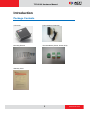
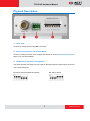
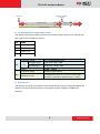
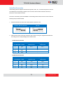
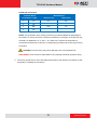
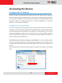
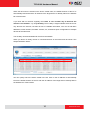
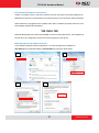
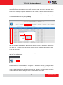
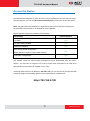
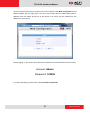
TCD-2100
1-channel H.264 Video Encoder
Hardware Manual
(DC 12V)
Ver. 2013/07/02
TCD-2100 Hardware Manual
Table of Contents
Precautions
3
Safety Instructions ........................................................................... 4
Introduction
6
Package Contents............................................................................. 6
Physical Description ........................................................................ 7
Basic Connections ......................................................................... 10
Serial Port Connection ................................................................. 11
Accessing the Device
13
Configure the IP Address ............................................................... 13
Access the Device .......................................................................... 17
2
www.acti.com
TCD-2100 Hardware Manual
Precautions
Read these instructions
You should read all the safety and operating instructions before using this product.
Heed all warnings
You must adhere to all the warnings on the product and in the instruction manual. Failure to
follow the safety instruction given may directly endanger people, cause damage to the system
or to other equipment.
Servicing
Do not attempt to service this video device yourself as opening or removing covers may
expose you to dangerous voltage or other hazards. Refer all servicing to qualified service
personnel.
Trademarks
All names used in this manual are probably registered trademarks of respective companies.
Liability
Every reasonable care has been taken during the writing of this manual. Please inform your
local office if you find any inaccuracies or omissions. We cannot be held responsible for any
typographical or technical errors and reserve the right to make changes to the product and
manuals without prior notice.
FCC/CE Regulation
NOTE: This equipment has been tested and found to comply with the limits for a Class A digital
device, pursuant to Part 15 of the FCC Rules. These limits are designed to provide reasonable
protection against harmful interference when the equipment is operated in a commercial
environment. This equipment generates, uses, and can radiate radio frequency energy and, if
not installed and used in accordance with the instruction manual, may cause harmful
interference to radio communications. Operation of this equipment in a residential area is likely
to cause harmful interference in which case the users will be required to correct the
interference at their own expense.
3
www.acti.com
TCD-2100 Hardware Manual
Safety Instructions
Don’t use the power supply with other voltages
If you use a power supply with different voltage than the one included with this device, this
device may be damaged or inflict damage upon other equipments / personnel. All warranty of
this product will be voided in the situations above.
Don’t open the housing of the product
Cleaning
Disconnect this video product from the power supply before cleaning.
Attachments
Do not use attachments not recommended by the video product manufacturer as they may
cause hazards.
Water and Moisture
Do not use this video product near water, for example, near a bathtub, washbowl, kitchen sink,
or laundry tub, in a wet basement, or near a swimming pool and the like.
Don’t use accessories not recommended by the manufacturer
Only install this device and the power supply in a dry place protected from weather
Servicing
Do not attempt to service this video product yourself as opening or removing covers may
expose you to dangerous voltage or other hazards. Refer all servicing to qualified service
personnel.
Damage Requiring service
Disconnect this video product from the power supply immediately and refer servicing to
qualified service personnel under the following conditions.
1) When the power-supply cord or plug is damaged
2) If liquid has been spilled, or objects have fallen into the video product.
3) If the video product has been directly exposed to rain or water.
4
www.acti.com
TCD-2100 Hardware Manual
4) If the video product does not operate normally by following the operating Instructions in
this manual. Adjust only those controls that are covered by the instruction manual, as an
improper adjustment of other controls may result in damage, and will often require
extensive work by a qualified technician to restore the video product to its normal
operation.
Safety Check
Upon completion of any service or repairs to this video product, ask the service technician to
perform safety checks to determine if the video product is in proper operating condition.
5
www.acti.com
TCD-2100 Hardware Manual
Introduction
Package Contents
TCD-2100
Power Adaptor (Optional)
Mounting Screws
Terminal Blocks (Power, Serial, DI/O)
Warranty Card
6
www.acti.com
TCD-2100 Hardware Manual
Physical Description
1) Video Input
Connect an analog camera using BNC connector.
2) Serial Port Connection via Terminal Block
Connect a serial port device to the supplied terminal block. See Serial Port Connection on
page 11 for connection details.
3) DIP Switch for Serial Port Configuration
The same terminal connections can be used for different protocols. Select which protocol to
use via this DIP Switch.
RS-485 or RS-422 (Default is RS-485)
RS-232 pin define
7
www.acti.com
TCD-2100 Hardware Manual
4) Power LED
The LED will light up after device has successfully completed the boot process
5) Serial Port LED
LED will light up when serial port is active
6) Power Input
Connect the power adaptor here if your power input is DC12V.
PIN
NAME
DESCRIPTION
1
12V
DC Power Input
2
GND
Ground Pin
7) Reset Button
Step 1: Switch off IP device by disconnecting the power cable
Step 2: Press and continue to hold the Reset Button (with a sharp tipped object, like a pen.)
Step 3: Reconnect the power cable while continuing to hold the reset button. The red
Power LED light will flash on for 3 second first, turn off for about 15 seconds, flash on for
another second and turn off again. By this time the reset to default operation is already
completed. This will take around 20 seconds from power up. You may then release the
reset button. This length of time fluctuates slightly with the environment. The Power LED light
will come back on and stay on after a few more seconds. The unit will start up with factory
default settings automatically.
8
www.acti.com
TCD-2100 Hardware Manual
Restore to Default
Complete
Power On
On (3s)
On
1s
Off (about 15s)
Off (10~15s)
Stay On
About 20 Seconds
8) Terminal Blocks for Digital Input / Output
The IP device supports one alarm input and one transistor output. Please connect DI with Pin 1
and 3 and connect DO with Pin 2 and 4.
PIN
NAME
1
GND
2
DC + 12V
3
Digital Input
4
Transistor Output
Connection design
DI
TTL-compatible logic levels
To trigger (low)
Logic level 0: 0V ~ 0.4V
Normal (high)
Logic level 1: 3.1V ~ 30V
Voltage
Current
10mA ~ 100mA
Connection design
Transistor (Open Drain)
DO
Voltage & Current
Internally powered at 12 V. Limit to no more than
24V DC if connected to external power, <100mA
9) Ethernet Port
The IP device connects to the Ethernet via a standard RJ45 connector. Supporting NWAY, this
IP device can auto detect the speed of local network segment (10Base-T/100Base-TX
Ethernet).
9
www.acti.com
TCD-2100 Hardware Manual
Basic Connections
Follow the procedures below to connect the IP device to the respective apparatuses.
1) Connect an analog camera to the IP device video in (BNC connector).
2) Connect the power adaptor to the IP device.
3) Connect IP device Ethernet port to the Network switch (via RJ45 connectors).
4) Connect a PC to the Network switch (via RJ45 connectors).
10
www.acti.com
TCD-2100 Hardware Manual
Serial Port Connection
If the analog camera supports functions like pan-tilt, zoom, etc., use the serial port to connect
the cables/pins of the analog camera to the IP device and use either RS-485, RS-422, or
RS-232 to control these functions.
Check the connection protocol available on the analog camera and connect it to the IP device
following the procedures below.
1. Set the DIP switch to select the communication protocol to use.
RS-485 / RS-422 (Default)
RS-232
2. Map the wires from the analog camera to the IP device using the supplied terminal block
according to the corresponding protocol table below:
Via RS-485 Connection
Terminal Block
Pin Number / Label
Wire Mapping
IP Device Pin
Camera Pin
1
TX +
TX +
TX +
2
TX -
TX -
TX -
3
RX+
-
4
Rx-
-
Via RS-422 Connection
Terminal Block
Pin Number / Label
Wire Mapping
IP Device Pin
Camera Pin
1
TX +
TX +
RX +
2
TX -
TX -
RX -
3
RX+
RX +
TX +
4
Rx-
RX -
TX -
11
www.acti.com
TCD-2100 Hardware Manual
Via RS-232 Connection
Terminal Block
Pin Number / Label
1
TX +
2
TX -
3
RX+
4
Rx-
Wire Mapping
IP Device Pin
Camera Pin
TX +
RX
RX +
TX
NOTE: The pins/cables of the analog camera may be labeled differently depending on
the location or country where the camera is purchased. For example, some devices may
have TX - pin labeled as "A” or “485 -”, etc. Refer to the camera documentation or
contact the manufacturer to verify the corresponding pin labels and ensure proper wiring
connection.
CAUTION: Incorrect wiring may cause damage to the connected devices.
DISCLAIMER: ACTi will not be responsible for any damage caused by improper wiring.
3. Connect a ground wire to one of the GND terminal pins of the IP device (via Power or DI/P
terminals) to complete the connection.
12
www.acti.com
TCD-2100 Hardware Manual
Accessing the Device
Configure the IP Address
In order to be able to communicate with the device from your PC, both the device and the PC
have to be within the same network segment. In most cases, it means that they both should
have very similar IP addresses, where only the last number of the IP address is different from
each other. There are 2 different approaches to IP Address management in Local Area
Networks – by DHCP Server or Manually.
Using DHCP server to assign IP address
If you have connected the computer and the device into the network that has a DHCP server
running, then you do not need to configure the IP addresses at all – both the device and the
PC would request a unique IP address from the DHCP server automatically. In such case, the
device will immediately be ready for the access from the PC. The user, however, might not
know the IP address of the device yet. It is necessary to know the IP address of the device in
order to access it using a Web browser.
The quickest way to discover the devices in the network is to use the simplest network
search, built in the Windows system – just by pressing the “Network” icon, all the devices of the
local area network will be discovered by Windows, thanks to the UPnP function support of our
devices.
In the example below, the device that has just been connected to the network is successfully
found.
13
www.acti.com
TCD-2100 Hardware Manual
When the left mouse is clicked on the device model name, the default browser of the PC is
automatically launched and the IP address of the target device is already filled in the address
bar of the browser.
If you work with our devices regularly, then there is even a better way to discover the
devices in the network – by using IP Utility. The IP Utility is a light software tool that can not
only discover the devices, but also list lots of valuable information, such as IP and MAC
addresses, serial numbers, firmware versions, etc, and allows quick configuration of multiple
devices at the same time.
The IP Utility can be downloaded for free from the website.
When you launch IP Utility, the list of connected devices in the network will be shown. See
sample illustration below:
You can quickly notice the device model in the list. Click on the IP address to automatically
launch the default browser of the PC with the IP address of the target device already filled in
the address bar of the browser.
14
www.acti.com
TCD-2100 Hardware Manual
Use the default IP address of the device
If there is no DHCP server in the given network, the user may have to manually assign the IP
addresses to both the PC and the device to make sure they are in the same network segment.
When the device is plugged into the network and it does not detect any DHCP services, it will
automatically assign itself a default IP:
192.168.0.100
Whereas the default port number would be 80. In order to access that device, the IP address of
the PC has to be configured to match the network segment of the device.
Manually adjust the IP address of the PC
In the following example, based on Windows 7, we will configure the IP address to
192.168.0.99 and set Subnet Mask to 255.255.255.0 by using the steps below:
1
3
2
4
15
www.acti.com
TCD-2100 Hardware Manual
Manually adjust the IP addresses of multiple devices
If there are more than one device to be used in the same local area network and there is no
DHCP server to assign unique IP addresses to each of them, all of the devices would then
have the initial IP address of 192.168.0.100, which is not a proper situation for network
devices – all the IP addresses have to be different from each other. The easiest way to assign
devices the IP addresses is by using IP Utility:
With the procedure shown above, all the devices will have unique IP addresses, starting from
192.168.0.101. In case there are 20 devices selected, the last one of the devices would have
the IP 192.168.0.120.
Later, by pressing the “Refresh” button of the IP Utility, you will be able to see the list of devices
with their new IP addresses.
Please note that it is also possible to change the IP addresses manually by using the Web
browser. In such case, please plug in only one device at a time, and change its IP address by
using the Web browser before plugging in the next one. This way, the Web browser will not be
confused about two devices having the same IP address at the same time.
16
www.acti.com
TCD-2100 Hardware Manual
Access the Device
Now that the device and the PC both have their unique IP addresses and are under the same
network segment, you can use Microsoft Internet Explorer on the PC to access the device.
Note: Only Microsoft Internet Explorer is supported by the device at the time of writing this
documentation. Please refer to our website for future upgrades.
Internet Explorer supports the following functionalities:
Functionality
Internet Explorer
Live Video
Yes
Live Video Area Resizable
Yes
Capture the snapshot
Yes
Video overlay based configuration
(Motion Detection regions, Privacy Mask regions)
All the other configurations
Yes
Yes
The ActiveX control for video stream management will be downloaded from the device
directly – the user has to accept the use of such control when prompted so. No other third
party utilities are required to be installed in such case.
Assuming that the device’s IP address is 192.168.0.100, you can access it by opening the Web
browser and typing the following address into the Web browser’s address bar:
http://192.168.0.100
17
www.acti.com
TCD-2100 Hardware Manual
Upon successful connection to the device, the user interface called Web Configurator would
appear together with the login page. The HTTP port number was not added behind the IP
address since the default HTTP port of the device is 80, which can be omitted from the
address for convenience.
Before logging in, you need to know the factory default Account and Password of the camera.
Account: Admin
Password: 123456
For further operations, please refer to the Firmware User Manual.
18
www.acti.com