Download Behringer FX2000

Transcript
User Manual
VIRTUALIZER 3D FX2000
High-Performance 3D Multi-Engine Effects Processor
2
VIRTUALIZER 3D FX2000 User Manual
Table of Contents
Thank you........................................................................ 2
Important Safety Instructions....................................... 3
Legal Disclaimer.............................................................. 3
Limited Warranty............................................................ 3
1. Introduction................................................................ 5
2. Effects Algorithms...................................................... 7
3. Operation.................................................................. 13
4. Applications.............................................................. 17
5. MIDI Functions of the FX2000................................. 19
6. Installation................................................................ 19
7. Appendix................................................................... 21
8. Specifications............................................................ 25
Thank you
In purchasing the BEHRINGER VIRTUALIZER 3D you have acquired an extremely
efficient multi-effects processor that offers first class reverberation effects and a
number of other algorithms. The FX2000 has 71 new effects types, and thanks to
its logically structured user interface, it can be used easily and intuitively.
3
VIRTUALIZER 3D FX2000 User Manual
Important Safety
Instructions
Terminals marked with this symbol carry
electrical current of sufficient magnitude
to constitute risk of electric shock. Use only
high-quality commercially-available speaker cables with
1/4" TS plugs pre-installed. All other installation or
modification should be performed only by
qualified personnel.
This symbol, wherever it appears,
alerts you to the presence of uninsulated
dangerous voltage inside the
enclosure - voltage that may be sufficient to constitute a
risk of shock.
This symbol, wherever it appears,
alerts you to important operating and
maintenance instructions in the
accompanying literature. Please read the manual.
Caution
To reduce the risk of electric shock, do
not remove the top cover (or the rear
section). No user serviceable parts inside. Refer servicing
to qualified personnel.
Caution
To reduce the risk of fire or electric shock,
do not expose this appliance to rain and
moisture. The apparatus shall not be exposed to dripping
or splashing liquids and no objects filled with liquids, such
as vases, shall be placed on the apparatus.
9. Do not defeat the safety purpose of the polarized
or grounding-type plug. A polarized plug has two blades
with one wider than the other. A grounding-type plug
has two blades and a third grounding prong. The wide
blade or the third prong are provided for your safety. If the
provided plug does not fit into your outlet, consult an
electrician for replacement of the obsolete outlet.
10. Protect the power cord from being walked on or
pinched particularly at plugs, convenience receptacles,
and the point where they exit from the apparatus.
11. Use only attachments/accessories specified by
the manufacturer.
12. Use only with the
cart, stand, tripod, bracket,
or table specified by the
manufacturer, or sold with
the apparatus. When a cart
is used, use caution when
moving the cart/apparatus
combination to avoid
injury from tip-over.
13. Unplug this apparatus during lightning storms or
when unused for long periods of time.
14. Refer all servicing to qualified service personnel.
Servicing is required when the apparatus has been
damaged in any way, such as power supply cord or plug
is damaged, liquid has been spilled or objects have fallen
into the apparatus, the apparatus has been exposed
to rain or moisture, does not operate normally, or has
been dropped.
15. The apparatus shall be connected to a MAINS socket
outlet with a protective earthing connection.
16. Where the MAINS plug or an appliance coupler is
used as the disconnect device, the disconnect device shall
remain readily operable.
Caution
These service instructions are for use
by qualified service personnel only.
To reduce the risk of electric shock do not perform any
servicing other than that contained in the operation
instructions. Repairs have to be performed by qualified
service personnel.
1. Read these instructions.
2. Keep these instructions.
3. Heed all warnings.
4. Follow all instructions.
5. Do not use this apparatus near water.
6. Clean only with dry cloth.
7. Do not block any ventilation openings. Install in
accordance with the manufacturer’s instructions.
8. Do not install near any heat sources such as
radiators, heat registers, stoves, or other apparatus
(including amplifiers) that produce heat.
LEGAL DISCLAIMER
TECHNICAL SPECIFICATIONS AND APPEARANCE
ARE SUBJECT TO CHANGE WITHOUT NOTICE.
THE INFORMATION CONTAINED HEREIN IS CORRECT
AT THE TIME OF PRINTING. ALL TRADEMARKS ARE
THE PROPERTY OF THEIR RESPECTIVE OWNERS.
MUSIC GROUP ACCEPTS NO LIABILITY FOR ANY
LOSS WHICH MAY BE SUFFERED BY ANY PERSON
WHO RELIES EITHER WHOLLY OR IN PART UPON
ANY DESCRIPTION, PHOTOGRAPH OR STATEMENT
CONTAINED HEREIN. COLORS AND SPECIFICATIONS
MAY VARY FROM ACTUAL PRODUCT. MUSIC GROUP
PRODUCTS ARE SOLD THROUGH AUTHORIZED
FULLFILLERS AND RESELLERS ONLY. FULLFILLERS AND
RESELLERS ARE NOT AGENTS OF MUSIC GROUP
AND HAVE ABSOLUTELY NO AUTHORITY TO BIND
MUSIC GROUP BY ANY EXPRESS OR IMPLIED
UNDERTAKING OR REPRESENTATION. THIS MANUAL
IS COPYRIGHTED. NO PART OF THIS MANUAL MAY
BE REPRODUCED OR TRANSMITTED IN ANY FORM
OR BY ANY MEANS, ELECTRONIC OR MECHANICAL,
INCLUDING PHOTOCOPYING AND RECORDING OF ANY
KIND, FOR ANY PURPOSE, WITHOUT THE EXPRESS
WRITTEN PERMISSION OF MUSIC GROUP IP LTD.
ALL RIGHTS RESERVED.
© 2011 MUSIC Group IP Ltd.
Trident Chambers, Wickhams Cay, P.O. Box 146,
Road Town, Tortola, British Virgin Islands
LIMITED WARRANTY
§ 1 Warranty
(1) This limited warranty is valid only if you purchased
the product from a MUSIC Group Authorized Reseller in
the country of purchase. A list of authorized resellers can
be found on BEHRINGER’s website behringer.com under
“Where to Buy“, or you can contact the MUSIC Group office
closest to you.
(2) MUSIC Group* warrants the mechanical and
electronic components of this product to be free of defects
in material and workmanship if used under normal
operating conditions for a period of one (1) year from
the original date of purchase (see the Limited Warranty
terms in § 4 below), unless a longer minimum warranty
period is mandated by applicable local laws. If the product
shows any defects within the specified warranty period
and that defect is not excluded under § 4, MUSIC Group
shall, at its discretion, either replace or repair the product
using suitable new or reconditioned product or parts.
In case MUSIC Group decides to replace the entire product,
this limited warranty shall apply to the replacement
product for the remaining initial warranty period, i.e.,
one (1) year (or otherwise applicable minimum warranty
period) from the date of purchase of the original product.
(3) Upon validation of the warranty claim, the repaired
or replacement product will be returned to the user freight
prepaid by MUSIC Group.
(4) Warranty claims other than those indicated above
are expressly excluded.
PLEASE RETAIN YOUR SALES RECEIPT. IT IS YOUR PROOF
OF PURCHASE COVERING YOUR LIMITED WARRANTY.
THIS LIMITED WARRANTY IS VOID WITHOUT SUCH PROOF
OF PURCHASE.
§ 2 Online registration
Please do remember to register your new BEHRINGER
equipment right after your purchase at behringer.com
under “Support” and kindly read the terms and conditions
of our limited warranty carefully. Registering your
purchase and equipment with us helps us process
your repair claims quicker and more efficiently.
Thank you for your cooperation!
§ 3 Return materials authorization
(1) To obtain warranty service, please contact the
retailer from whom the equipment was purchased.
Should your MUSIC Group Authorized Reseller not be
located in your vicinity, you may contact the MUSIC Group
Authorized Fulfiller for your country listed under
4
VIRTUALIZER 3D FX2000 User Manual
“Support” at behringer.com. If your country is not
listed, please check if your problem can be dealt with
by our “Online Support” which may also be found under
“Support” at behringer.com. Alternatively, please submit
an online warranty claim at behringer.com BEFORE
returning the product. All inquiries must be accompanied
by a description of the problem and the serial number
of the product. After verifying the product’s warranty
eligibility with the original sales receipt, MUSIC Group
will then issue a Return Materials Authorization
(“RMA”) number.
(2) Subsequently, the product must be returned in
its original shipping carton, together with the return
authorization number to the address indicated by
MUSIC Group.
(3) Shipments without freight prepaid will not
be accepted.
§ 4 Warranty Exclusions
(1) This limited warranty does not cover consumable
parts including, but not limited to, fuses and batteries.
Where applicable, MUSIC Group warrants the valves or
meters contained in the product to be free from defects in
material and workmanship for a period of ninety (90) days
from date of purchase.
(2) This limited warranty does not cover the product
if it has been electronically or mechanically modified
in any way. If the product needs to be modified or
adapted in order to comply with applicable technical
or safety standards on a national or local level, in any
country which is not the country for which the product
was originally developed and manufactured, this
modification/adaptation shall not be considered a defect
in materials or workmanship. This limited warranty does
not cover any such modification/adaptation, regardless
of whether it was carried out properly or not. Under the
terms of this limited warranty, MUSIC Group shall not
be held responsible for any cost resulting from such a
modification/adaptation.
(3) This limited warranty covers only the product
hardware. It does not cover technical assistance for
hardware or software usage and it does not cover
any software products whether or not contained in
the product. Any such software is provided “AS IS”
unless expressly provided for in any enclosed software
limited warranty.
(4) This limited warranty is invalid if the factoryapplied serial number has been altered or removed from
the product.
(5) Free inspections and maintenance/repair work
are expressly excluded from this limited warranty, in
particular, if caused by improper handling of the product
by the user. This also applies to defects caused by normal
wear and tear, in particular, of faders, crossfaders,
potentiometers, keys/buttons, guitar strings, illuminants
and similar parts.
(6) Damage/defects caused by the following conditions
are not covered by this limited warranty:
• improper handling, neglect or failure to operate the
unit in compliance with the instructions given in
BEHRINGER user or service manuals;
• connection or operation of the unit in any way
that does not comply with the technical or safety
regulations applicable in the country where the
product is used;
• damage/defects caused by acts of God/Nature
(accident, fire, flood, etc) or any other condition that
is beyond the control of MUSIC Group.
(7) Any repair or opening of the unit carried out by
unauthorized personnel (user included) will void the
limited warranty.
(8) If an inspection of the product by MUSIC Group
shows that the defect in question is not covered by the
limited warranty, the inspection costs are payable by
the customer.
(9) Products which do not meet the terms of this
limited warranty will be repaired exclusively at the buyer’s
expense. MUSIC Group or its authorized service center will
inform the buyer of any such circumstance. If the buyer
fails to submit a written repair order within 6 weeks after
notification, MUSIC Group will return the unit C.O.D. with
a separate invoice for freight and packing. Such costs will
also be invoiced separately when the buyer has sent in a
written repair order.
(10) MUSIC Group Authorized Resellers do not sell new
products directly in online auctions. Purchases made
through an online auction are on a “buyer beware” basis.
Online auction confirmations or sales receipts are not
accepted for warranty verification and MUSIC Group will
not repair or replace any product purchased through an
online auction.
§ 5 Warranty transferability
This limited warranty is extended exclusively to the
original buyer (customer of authorized reseller) and is
not transferable to anyone who may subsequently
purchase this product. No other person (reseller, etc.)
shall be entitled to give any warranty promise on behalf
of MUSIC Group.
§ 6 Claim for damage
Subject only to the operation of mandatory applicable
local laws, MUSIC Group shall have no liability to the buyer
under this warranty for any consequential or indirect
loss or damage of any kind. In no event shall the liability
of MUSIC Group under this limited warranty exceed the
invoiced value of the product.
§ 7 Limitation of liability
This limited warranty is the complete and exclusive
warranty between you and MUSIC Group. It supersedes
all other written or oral communications related to this
product. MUSIC Group provides no other warranties for
this product.
§ 8 Other warranty rights and
national law
(1) This limited warranty does not exclude or limit the
buyer’s statutory rights as a consumer in any way.
(2) The limited warranty regulations mentioned herein
are applicable unless they constitute an infringement of
applicable mandatory local laws.
(3) This warranty does not detract from the seller’s
obligations in regard to any lack of conformity of the
product and any hidden defect.
§ 9 Amendment
Warranty service conditions are subject to change without
notice. For the latest warranty terms and conditions
and additional information regarding MUSIC Group’s
limited warranty, please see complete details online at
behringer.com.
* MUSIC Group Macao Commercial Offshore Limited of
Rue de Pequim No. 202-A, Macau Finance Centre 9/J, Macau,
including all MUSIC Group companies
5
VIRTUALIZER 3D FX2000 User Manual
1. Introduction
In order to generate an extremely natural reverberation, we at BEHRINGER
have developed new kinds of algorithms for virtual acoustics. These algorithms
will help you calculate all room and reverberation parameters with absolutely
professional quality and naturalness.
In spite of this extensive and calculation-intensive work performed by the
24-bit processor in the FX2000, the VIRTUALIZER 3D is very easy to handle.
Changing parameters to achieve a specific sound is simple. There are 100 presets
available to store your own programs.
The FX2000 includes excellent reverb and delay programs, but that’s not all.
Besides the classic plate reverb simulations, the VIRTUALIZER 3D will impress
you with its excellent modulation effects (like chorus, flanger and phaser),
which were extended to include special variations like a musical pitch shifter,
a tremolo, and a rotary speaker simulation. The FX2000’s dynamic and psychoacoustic effects allow you to do without a number of additional pieces of
equipment. The FX2000 also offers you a series of distortion and amplification
sounds that are combined with a speaker simulation. Thus, as a guitarist in
recording situations, you can achieve an excellent sound on tape or hard disk,
even without a speaker cabinet. Besides its logical and simple operation,
the VIRTUALIZER 3D’s technical equipment is also impressive. The following
points ensure signal processing at a professional level:
• Extremely low-noise and exact 24-bit A/D and D/A converters.
• A professional sample rate of 46 kHz guarantees a high signal resolution for
a frequency response of 20 Hz to 20 kHz.
• The 24-bit processor features dual engine software; these two sections
process audio input independently.
• As for all BEHRINGER products, the highest quality components and controls
are used.
◊ The following instructions will give you a brief run-down on the
terminology and functions of the VIRTUALIZER 3D. After reading,
please store this manual in a safe place for future reference.
1.1 The concept
BEHRINGER uses an uncompromising selection of components. The heart of the
BEHRINGER VIRTUALIZER 3D is a 24-bit DSP, which, due to its exceptional technical
specifications, is regarded as one of the finest building blocks. With it come the
first class 24-bit A/D-D/A converters, guaranteeing a precise conversion of audio
signals. Narrow-range tolerance resistances and capacitors, high-grade switches,
and other selected components are all very high in quality.
The VIRTUALIZER 3D was manufactured on the basis of SMD technology
(Surface Mounted Device). The use of sub-miniature building blocks known from
space flights allows not only an extreme packing density but also ensures an
increased dependability. The FX2000 was manufactured under ISO9000 certified
management system.
1.2 Before you get started
The VIRTUALIZER 3D was carefully packed in the factory to ensure safe transport.
Nevertheless, if the box shows signs of damage, please check the equipment
immediately for any signs of external damage.
◊ Damaged units should NEVER be sent directly to us. Please inform the
dealer from whom you acquired the unit immediately as well as the
transportation company from which you took delivery of the unit.
Otherwise, all claims for replacement/repair may be rendered invalid.
◊ To assure optimal protection of your FX2000 during use or transport,
we recommend utilizing a carrying case.
◊ Please always use the original packaging to avoid damage due to
storage or shipping.
◊ Never let unsupervised children play with the FX2000 or with
its packaging.
◊ Please dispose of all packaging materials in an environmentally-
friendly fashion.
The BEHRINGER VIRTUALIZER 3D requires one standard 19" rack unit of space
(1 3/4"). Please leave an additional 4" installation depth to allow connections at
the rear side.
Make sure that there is adequate ventilation and do not place the VIRTUALIZER 3D
on top of an amplifier, which could cause overheating.
◊ Before connecting the VIRTUALIZER 3D to the mains, carefully check
that your equipment is set to the correct voltage:
The fuse holder on the female mains connector has 3 triangular markings,
with two of these triangles opposing each other. The VIRTUALIZER 3D is set to
the operating voltage printed next to these markers and can be set to another
voltage by turning the fuse holder by 180°. CAUTION: This instruction
does not apply to export models exclusively designed, e.g. for
120-V operation!
Connection to the mains is made by a mains cable with an IEC receptacle that
complies with the required safety regulations.
◊ Please make sure that the unit is grounded at all times. For your own
protection, you should never tamper with the grounding of the cable
or the unit itself. The unit shall always be connected to a mains socket
outlet with a protective earthing connection.
◊ Installation and operation of this equipment must be carried out by
competent staff only. Both before and after installation, the staff using
the equipment should make sure that it is properly grounded since
otherwise electrostatic discharge etc. can lead to an impairment of its
operation. For more information, see chapter 6 “Installation”.
The BEHRINGER VIRTUALIZER 3D is equipped with electronically servo-balanced
inputs and outputs. The circuit design features automatic hum suppression for
balanced signals and thus ensures trouble-free operation, even at the highest
operating levels. Externally induced mains hum, etc. can therefore be effectively
suppressed. The automatic servo-function recognizes the presence of unbalanced
connectors and adjusts the nominal level internally to avoid level differences
between the input and output signals (6-dB correction).
The MIDI connectors (IN/OUT/THRU) are standard DIN plug connections. The data
communication is isolated from ground by opto-couplers.
1.3 Online registration
Please register your new BEHRINGER equipment right after your purchase
by visiting http://behringer.com and read the terms and conditions of our
warranty carefully.
Should your BEHRINGER product malfunction, it is our intention to have it
repaired as quickly as possible. To arrange for warranty service, please contact
the BEHRINGER retailer from whom the equipment was purchased. Should your
BEHRINGER dealer not be located in your vicinity, you may directly contact
one of our subsidiaries. Corresponding contact information is included in the
original equipment packaging (Global Contact Information/European Contact
Information). Should your country not be listed, please contact the distributor
nearest you. A list of distributors can be found in the support area of our website
(http://behringer.com).
Registering your purchase and equipment with us helps us process your repair
claims more quickly and efficiently.
Thank you for your cooperation!
6
VIRTUALIZER 3D FX2000 User Manual
1.4 Control elements
Fig. 1.1: VIRTUALIZER 3D front panel
The BEHRINGER VIRTUALIZER 3D’s front panel includes five edit controls
(non-intermittent rotary controls), a jog wheel (big rotary control), six parameter
keys, an LED display and a mains switch. Each of the two fully independent
channels can be monitored with an 8-digit LED meter.
(3)
(5) Every preset in the FX2000 allows you to edit at least four effect parameters.
The EDIT-LED-CHAIN indicates which parameters are adjusted by the four
EDIT CONTROLs. If the top LED lights up, (6) controls the parameter EDIT A,
(7) controls EDIT B, (8) helps in changes of parameter EDIT C and with (9)
you change the setting of parameter EDIT D. If the middle LED of the EDITLED-CHAIN lights up, the four EDIT CONTROLs modify the parameters that are
arranged to its left and right. The lower LED functions correspondingly.
◊ For the exact meaning of the individual effect parameters,
see chapter 7.1.
(1)
(2)
(6) With the 1st EDIT CONTROL (non-intermittent rotary control) you change
the values of the first (EDIT A) and fifth (EDIT E) effect parameters. You can
also select MIDI functions (MIDI) with the 1st EDIT CONTROL. Press the EDIT
key (13) to switch from EDIT A to EDIT E and vice versa. You reach the MIDI
function by pressing the SETUP key (16) .
(4)
Fig. 1.2: Display section of the VIRTUALIZER 3D
(1) Both the LED chains display the intensity of the input signal in dB in
relation to the nominal level, which is selected on the rear panel with the
OPERATING LEVEL switch.
(2) After you switch on the VIRTUALIZER 3D, you can read the name of the last
used effect on the LED display. When editing, the LED display shows the
parameter’s name along with a 4-digit alpha-numeric display that shows the
absolute parameter’s value.
(3) To the right of the LED display are four STATUS LEDs which indicate the type
of value you are working with. You may do any of the following:
• set the absolute value of an effect parameter (“%”),
• increase or decrease the amplitude or determine the threshold point of the
compressor (“dB”),
• modify a frequency (“Hz”) or
• modify a time parameter (“sec”).
(4) The ALGORITHM GROUPS LED CHAIN indicates which category the
selected effect belongs to. Altogether the FX2000 offers eight different
algorithm groups.
(6) (7) (8) (9) (10) (12) (11) (14) (15)
(7) The 2nd EDIT CONTROL allows you to modify the values of effect
parameters EDIT B and EDIT F. When you select the INPUT parameter with
the help of the SETUP key, you can specify whether the FX2000 functions
mono or stereo mode (see chapter 3.6.2 for more information).
(8) The 3rd EDIT CONTROL modifies the values of effect parameters EDIT C,
EQ LO, and the global OUTPUT parameter (see chapter 3.6.3). Here, as well,
you select among them using the EDIT and SETUP keys.
(9) With the 4th EDIT CONTROL, you modify the values of effect parameters
EDIT D, EQ HI, and the global parameter CONFIG (see chapter 3.6.4). Use the
EDIT and SETUP keys to choose between the parameters.
◊ During editing, you can rotate one of the four EDIT CONTROLs minimally
to display a brief description of the current parameter active. This can
help you know that, for example, EDIT A controls the pre delay for all
reverb effects of the VIRTUALIZER 3D. After approximately one second
the name is erased and the parameter’s current value is displayed.
This function can be used only by operating one of the controls that has
not yet been selected.
(10) By turning the MIX/BYPASS CONTROL the effect levels of most effect
algorithms are set in the range from 0 to 100%. If you select 0%, the signal
at the inputs of FX2000 is transferred directly to the outputs without adding
any effects (the signal is completely dry). If you select 100%, only the
effected signal is sent to the outputs (the signal is completely wet).
◊ If you use the FX2000 in the aux bus with your mixing console,
you should always set this value at 100%. if you’re using the FX2000
with a guitar amplifier (in a serial effects loop), we suggest settings
between 20 and 50% (depending on the amplifier type).
◊ Please note that, for the effects “parametric” and “graphic EQ”,
(5)
Fig. 1.3: Function keys, controls and jog wheel
(13)
(16) (17) (18)
the MIX/BYPASS CONTROL allows a gain correction by rotation.
To bypass the FX2000’s effects, press the MIX/BYPASS CONTROL. This allows
you to compare between the original and the effected signals. Press the
MIX/BYPASS CONTROL again to deactivate the bypass and return to your
chosen effect. When the MIDI IN LED below the control flickers, it indicates
that MIDI data is arriving at the MIDI IN port.
7
VIRTUALIZER 3D FX2000 User Manual
(19)
(20)
(21)
(22)
(23)
(24)
Fig. 1.4: VIRTUALIZER 3D rear panel
◊ Both the MIX/BYPASS CONTROL and the four EDIT CONTROLs react
dynamically. This means that, depending how fast you rotate the
wheels, the present parameter is changed in steps of 1, 2, 5 or 10.
The faster the rotation, the greater the change in the parameter value.
(11) To select one of the 200 presets, press the PRESET key once, then rotate the
JOG WHEEL (17) .
(12) To select one of the 71 basic effect algorithms, press the EFFECT key once,
then rotate the JOG WHEEL. For information on the parameter values that
are set for the basic effect algorithms, see chapter 7.4.
(13) To select the EDIT CONTROL function (see (6) - (9) ), press the EDIT key.
(14) When you make changes to a user preset, the STORE key’s LED begins to
blink. The FX2000 comprises 100 user presets for your own settings and
100 factory presets (see separate preset sheet). To save your changes,
press the STORE key. Select a storage space (number) with the Jog Wheel and
confirm it by pressing the STORE key again.
(15) If you have made changes to a preset and the LED of the STORE key is
blinking, you can press the COMPARE key to temporarily restore the preset’s
original settings. While these settings are loaded, the COMPARE key’s LED
blinks and “COMP” appears in the LED display. Press the COMPARE key again
to return to edit mode and store your changes.
(16) To enter SETUP mode, press the SETUP key. In setup mode, you can access
the parameters shown below the four EDIT CONTROLs. For more information
about SETUP mode, see chapter 3.6.
(17) To change a parameter’s value, rotate the JOG WHEEL. To increase the
value, turn the wheel clockwise. To decrease the value, turn the wheel
counterclockwise. If none of the edit functions is selected, you can select a
program directly with the Jog Wheel. When you do so, a spot lights up in the
LED display. As long as the spot is illuminated, a program can be selected
without making the corresponding settings immediately audible. This brief
signal suppression means that during quick selection of presets with the
Jog Wheel, not every preset is activated directly. If the Jog Wheel is not
turned for a second, the spot in the LED display disappears and the program
is loaded.
(18) Use the POWER switch to power up your FX2000. The POWER switch should
always be in the “Off” position when you are about to connect your unit to
the mains.
◊ To disconnect the unit from the mains, pull out the mains cord plug.
When installing the product, ensure that the plug is easily accessible.
If mounting in a rack, ensure that the mains can be easily disconnected
by a plug or by an all-pole disconnect switch on or near the rack.
(19) FUSE HOLDER / VOLTAGE SELECTION. Before connecting the FX2000,
confirm that the voltage display matches your local mains voltage.
When replacing the fuse, you must always use the same type. In many
units the fuse holder can be installed in one of two positions, allowing you
to switch between 230 V and 120 V. If you wish to operate a unit outside
Europe at 120 V, then a stronger fuse must be used. (For more information,
see chapter 8 “SPECIFICATIONS”). The mains connection is made via the IEC
receptacle. An appropriate mains cable is included.
(20) The FX2000 has wide-ranging MIDI implementation. MIDI IN, MIDI OUT,
and MIDI THRU connectors are available for transmitting MIDI commands.
(21) SERIAL NUMBER. Please complete and return the warranty card within
14 days of the date of purchase. Otherwise, you will lose your right to the
extended warranty. Alternatively, you can register online at our website
under behringer.com.
(22) The FX2000’s balanced OUTPUTs are designed as 1/4" TRS and XLR sockets.
(23) To switch between -10 dBV (home recording level) and +4 dBu
(professional studio level), use the OPERATING LEVEL SWITCH. When you
switch between the two, the level displays are automatically changed to the
nominal level and the VIRTUALIZER 3D operates in its optimal working range.
(24) Both of the VIRTUALIZER 3D’s INPUTs are also available as balanced 1/4" TRS
and XLR sockets.
2. Effects Algorithms
All effects of digital effects equipment are based on various algorithms.
An algorithm for a reverb effect, for example, is programmed differently than a
chorus algorithm. Each effect has a certain algorithm with which the digital input
signal is processed. The processing takes place within the digital signal processor
(DSP). After the effect is generated and the input signal is mixed, the digital
signal is converted back into an analog signal with a D/A converter.
You can edit up to seven parameters for each preset in the VIRTUALIZER 3D.
The changes you make will influence the sound in different ways. An overview of
the FX2000’s various effects algorithms follows.
REVERB
2.1 Reverb algorithms
REVERB: As the term suggests, a “reverb” is a reverberation effect. The reverb
can be considered as the most important effect in a mix-down or a live event.
The FX2000 offers 12 different reverberation programs so that you have a suitable
reverb for every situation. Cathedral simulates the dense, long reverberation
of a large cathedral, which is appropriate for solo instruments or vocals in
slow pieces. Gold Plate simulates the sound of plate reverberators and
hence is a classic for drums (snare) and vocals. Small Hall simulates a small,
lively (strongly reflecting) hall. With Room, you can clearly hear the walls of
the room. Studio represents a small- to middle-sized room. With Concert,
you can select between a small theater and a large hall. Stage is well suited
to dissipating the sound of a keyboard or an acoustic guitar. Spring Reverb
simulates a classic spring reverberation. Ambience reproduces a room
impression without late reflections. With Early Reflections, the initial
reflections of a room are clearly audible.
GATED REVERB: This effect synthetically cuts off reverberation after a period of
time. It is famous in the song “In the Air Tonight” by Phil Collins.
REVERSE REVERB: This is a reverberation in which the envelope is
reversed—it slowly gets louder.
8
VIRTUALIZER 3D FX2000 User Manual
Parameter
Function
Pre Delay
Decay
Hi Decay Damping
Size
Diffusion
Wall Damp.
Bass Mul.
Low Cut
Metal Resonance
Reflections
Shelver Damp.
High Cut
Stereo Width
Reverb Mod.
ER/Rev.
Density
Time until arrival of first reflection(s)
Duration until the reverb tail is damped
Damps high frequencies in the reverb tail
Size of the plate reverb/the room impression
Degree of wall diffusion (reverb density)
Degree of damping of the wall material
Amplification/damping of low frequencies in the
reverb tail
Frequency of Low Cut Filter1 at the input stage
Intensity of metal resonances
Number of initial reflections
Damps Shelving Filter2 at the input stage
Frequency response of spring reverb (Spring Reverb)
Stereo depth of the effect
Modulation intensity of the reverb tail
Intensity ratio between initial reflections and reverb tail
Intensity of reflection envelope build-up (Gated / Reverse Reverb)
Tab. 2.1: Functioning of the reverb effects’ parameters
1 High pass filter, allows the frequencies above a specific cut-off frequency to pass and damps the frequencies
below that."
2 Upper or lower cut-off frequency of an equalizer.
DELAY
2.2 Delay algorithms
STEREO DELAY: A delay of the input signal. Different tempo settings allow
interesting delay effects.
TAPE ECHO: Similar to the stereo delay, with the difference being that the
repetitions have less presence. This simulates the character of the original
tape echo that was used before the digital era and can be thought of as a
“Vintage Sound”. The tape echo’s reflections include high and low pass filters.
PING PONG: A delay effect with changing stereo positioning, where the time
intervals between the repetitions can be changed.
Parameter
Delay Left
Delay Left Coarse
Delay Left Fine
Delay Right
Delay Right Coarse
Delay Right Fine
Feedback
Feedback Left
Feedback Right
Feedback Delay Left
Feedback Delay Right
Feedback HP
Feedback LP
Damping
Function
Length of left delay (Tape Echo / Ping Pong)
Length of delay time (left) in 100 ms steps
Length of delay time (left) in 1 ms steps
Length of right delay (Tape Echo / Ping Pong)
Length of delay time (right) in 100 ms steps
Length of delay time (right) in 1 ms steps
Repetition(s) for both channels
Repetition(s) for the left channel
Repetition(s) for the right channel
Delay of the left feedback
Delay of the right feedback
High pass cut-off frequency of repetition(s)
Low pass1 cut-off frequency of repetition(s)
Low pass frequency within the delay feedback loop
(Tape Echo)
Tab. 2.2: Functioning of the delay effects’ parameters
1 Filter, allows the frequency below a particular cut-off frequency to pass and damps the frequencies
above that."
MODULATION
2.3 Modulation and pitch shifter effects
FLANGER: The word “flange” means “tape spool”, and this explains the
characteristics of the effect. Originally the flanger effect was generated with two
tape recorders which ran synchronously. The same audio signal was recorded
on both machines. If you put a finger on the left spool of one of the machines,
the spool and the playback speed are slowed down. The generated delay results
in phase shifting of the signals. Vintage Flanger simulates a guitar flanger
effect pedal and Jet Stream Flanger sounds like a classic analog flanger.
CHORUS: This effect slightly detunes the original signal. A very pleasant detune
effect is created in connection with the pitch variation. The chorus effect is quite
often and extensively used for dispersing signals. Analog Chorus simulates a
guitar chorus effect pedal, while Vintage Chorus imitates a classic analog studio
chorus. Ultra Chorus creates the sound of an eight-person vocal chorus.
PHASER: With the phaser, a second, phase shifted signal is added to the original
audio signal. The resulting sound is thicker and above all livelier. This effect is
often used for guitar sounds and keyboards. In the 70s, it was also extensively
used for other instruments like electric pianos. Here, Vintage Phaser represents
a guitar phaser effect pedal. Dual Phaser processes the left and the right
channels separately.
LESLIE: The simulation of a classic effect that is normally generated with a
very heavy enclosure with a (slow or fast) rotating speaker: The bass speaker
(drum) is covered by a partly opened rotating cap, while both of the high pitch
horns (horn), displaced by 180°, revolve around the same perpendicular axis.
Here, the physical principle of the Doppler effect for modulation of signals is used.
PITCH SHIFTER: This effect changes the pitch of the input signal. You can
generate musical intervals and harmonies or simply a single voice. Detuning by
several semitones upward alienates voices (and is used often in cartoons).
Here, you can choose among a stereo, two, and three vocal pitch shifter.
At the left stop of Edit C the pitch shifters 1 and 2 are synchronized to a
stereo pitch shifter. Pitch shifter 3 can be switched off by turning Edit E
fully counterclockwise.
VIBRATO: For this effect, the peak frequency of a tone is periodically and
uniformly changed (quickly or slowly). It is often used for guitar playing.
TREMOLO: This effect was originally found on guitar amplifiers, and is once again
trendy. It is a fast or slow periodic variation of the volume.
AUTO PANNING: This sound effect, which was very popular in the beginnings of
stereo technique, is achieved by allowing a sound source (often the lead guitar or
a synthesizer) to wander from one end of the stereo image to another or by just
letting it wander repeatedly.
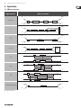
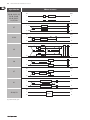
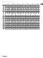
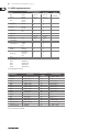
9
VIRTUALIZER 3D FX2000 User Manual
Parameter
Function
Speed
LFO1 Wave
Depth
Delay
Feedback
Wave
Semitones 1
Semitones 2
Semitones 3
Cents 1
Cents 2
Cents 3
Drum Depth
Horn Depth
Balance
Stereo Spread
Stereo Phase
Wideness
Base
Drive
Mode
Auto Modulation
Feedback LP
Damping
Speed of modulation
Sets the curve of the modulation
(triangular, sinusoidal, rectangular)
Modulation depth (L & R)
Length of delay
Routes back the processed signal to the input stage
Sets the curve of the LFO (Sine, Tri, Opto, Square,
Saw Up, Saw Down)
Pitch Shifter 1: detuning in semitones
Pitch Shifter 2: detuning in semitones
Pitch Shifter 3: detuning in semitones
Pitch Shifter 1: detuning in cents
Pitch Shifter 2: detuning in cents
Pitch Shifter 3: detuning in cents
Intensity of amplitude modulation of the bass loudspeaker (Leslie)
Intensity of amplitude modulation of the high pitch horn (Leslie)
Volume ratio between horn and drum
Stereo effect intensity
Phase angle between left and right modulation
Parameter variation (Ultra Chorus)
Starting point of modulation
Intensity of tube distortion
Selects various effect modes or between three modes with
increasing modulation intensity (Stereo Phaser)
Influences LFO frequency (dependent on input level)
Low pass cut-off frequency of feedback
Limits frequency range to simulate older chorus units
(Stereo / Vintage Chorus)
Tab. 2.3: Functioning of the modulation and pitch shifter effects’ parameters
1 (Low Frequency Oscillator): determines the speed and nature of modulation effects.
DYNAMICS
2.4 Dynamic effects
COMPRESSOR/LIMITER: When the signal level exceeds the level control limit of
the signal-processing unit, it must be limited dynamically to avoid distortions.
This is achieved by installing a compressor or a limiter. The limiter abruptly limits
the signal above a specified threshold, while a compressor acts “softly” over
a large range. The Analog Compr/Limiter is modeled after a famous analog
compressor unit.
EXPANDER: Background noises of all types (noise, humming etc) limit the
dynamic range of the actual signal. As long as the level of the actual
signal lies significantly above the background noise, the noise is inaudible.
The interference signal in this case is masked by the actual signal. The expander
is used to effectively expand the dynamic range of signals. Signals with small
amplitudes (such as background noise) can be weakened, thereby reducing the
background noise.
GATE: On stage and in studios, there are diverse applications where a noise
gate is needed. For example, microphones that tend to cause feedback can
be “defused”. In addition, you can use a gate to eliminate unwanted noise.
When used on vocals, for example, the signal is simply masked during pauses,
thus eliminating all noise. Needless to say, a gate used on vocals has to open very
quickly—otherwise, the first syllables of soft or whispered passages would not
be audible.
ULTRAMIZER: The ultramizer function divides the sound spectrum into two
frequency bands and, as a result, allows inaudible but extremely effective
compression. This is especially helpful during mix-down. The FX2000 analyses
the received audio material and automatically adjusts input gain and
compression parameters.
DENOISER: The denoiser is used to eliminate or reduce noise and
other interference.
DE-ESSER: A problem often encountered in recording situations, is the sibilant
(Ssss) sound of the human voice. The de-esser is used to remove strong hissing
sounds from the audio signal.
WAVE DESIGNER: Using this effect, you can influence the envelope of a signal by
specifying its volume. A (= Attack) indicates the time a tone needs to reach its
full volume. R (= Release) determines how long it takes before a tone dies away.
Parameter
Ratio1
Threshold
Limiter Threshold
M-Gain
Gain L
Gain R
Soft Knee
Attack3
Attack L
Attack R
Release4
Release L
Release R
Hold5
Range
Density
Speed
Split Frequency
Stereo FX
Enhancer Frequency
Band
LP Frequency
LP Depth
LP Speed
Gate Hold
Gate Response
Gate Threshold
Frequency
Function
Degree of compression (Compressor) / expansion (Expander)
Threshold point of Compressor / Expander / Gate
Threshold point of Limiter
Make-up gain
Make-up gain for left channel
Make-up gain for right channel
Bending of the characteristic curve2 at the threshold point
Response time
Response time of left channel (Wave Designer)
Response time of right channel (Wave Designer)
Release (right stop activates auto mode for Compr./Lim.)
Release of left channel
Release of right channel
Time until release process sets in
Degree of damping (Gate); dynamic limitation (Ultramizer)
Degree of compression (Ultramizer)
Recovery time (the higher the faster)
Split point between high and low band
Intensity of the stereo enhancer
Frequency of the HF6 enhancer
Separates low, high band & wide (Ultramizer / De-Esser)
Basic frequency (Denoiser)
Controls the amount of influence on the signal level (Denoiser)
Recovery time of low pass modulation (Denoiser)
Time until the gate process sets in (Denoiser)
Gate recovery time (Denoiser)
Amount of signal needed to open the noise gate (Denoiser)
Lower cut-off frequency of compression process (De-Esser)
Tab. 2.4: Functioning of the dynamic effects’ parameters
1 Ratio determines the relation of input to output level for all signals which exceed the threshold point.
2 The Soft Knee characteristic curve prevents a high compression rate (high ratio) from sounding unnatural.
3 Attack determines the time which the processor requires to react to signals which exceed the threshold point.
4 Release determines the time that the processor needs after falling below the threshold point to reach the
original level.
5 Hold determines the time before the release process sets in (release sets in after the signal falls below the
threshold point).
6 High frequency.
10
VIRTUALIZER 3D FX2000 User Manual
PSYCHO
ACOUSTICS
FILTER/EQ
2.5 Psycho-acoustic effects
2.6 Filter/EQ effects
EXCITER: An exciter works with psycho-acoustic principles to add artificially
generated overtones to the original signal, thereby increasing its presence and
loudness (the subjective volume impression) without any significant increase of
the signal level.
FILTER: Filters, in general, influence the frequency response of a signal. A low
pass filter allows low frequencies to pass and suppresses high frequencies,
while a high pass filter allows high frequencies to pass and suppresses
low frequencies.
ENHANCER: The enhancer works like a dynamic pitch equalizer. Its effectiveness
depends on the associated high frequencies and the intensity of the input signal.
PARAMETRIC EQ: The parametric equalizer is the most highly-developed
form of equalization. You can control the three parameters which define the
so-called gauss equalizer curve: bandwidth, frequency and amplitude boosting
or lowering.
ULTRA BASS: This awesome combination of sub-harmonic processor,
bass exciter, and limiter adds a final touch to your music production.
STEREO IMAGER: This effect is used to process stereo main signals. The signal is
first subdivided into middle and side signal (MS Matrix). Both parts can then be
amplified when desired and placed on the stereo image.
ULTRA WIDE: This effect is suitable to pep up speaker systems with an especially
broad stereo image.
BINAURALIZER: The binauralizer also extends the stereo image. Additionally,
it compensates for inter-channel cross talk of both speakers (left loudspeaker on
right ear and vice versa).
Parameter
Gain
Frequency
Function
Gain correction
Cut-off frequency of the side chain high pass filter1 (Exciter)
Resonance of the high pass filter (emphasizes cut-off frequency
Filter Q
for Exciter)
Timbre
Ratio of straight and unstraight harmonics (Exciter)
Activates an amplification of harmonics dependent on the input
Harmonics Kick
level (Exciter)
Mix
Controls amount of harmonics (Exciter)
Bass Gain
Degree of the bass enhancer
Sub-bass Frequency
Cut-off frequency of the sub-bass low pass filter (Ultra Bass)
Sub-bass Level
Degree of sub-harmonics
Harmonics
Degree of synthetic harmonics (Exciter)
Harmonics Density
Density of harmonics (Ultra Bass)
Bass Gain
Degree of original bass signal (Ultra Bass)
Controls the influence on the stereo signal (Stereo Imager) /
Spread
degree of stereo expansion (Ultra Wide)
Spread Mode
Selects between two different spread variations (Stereo Imager)
MS Balance
Ratio of middle and side signal (Stereo Imager)
Stereo Balance
Balance of stereo signal (Stereo Imager)
Mono Balance
Balance of mono signal (Stereo Imager)
Amount of center impression in the stereo signal
Center
(Ultra Wide / Binauralizer)
Xover Frequency
Frequency of the crossover filter for the center signal (Ultra Wide)
Space
Degree of stereo wideness (Binauralizer)
Mode
Selects between headphones and speaker operation (Binauralizer)
Speaker Distance
Run time / speaker distance (Binauralizer)
Speaker Compensation
Degree of crosstalk compensation (Binauralizer)
High Frequency
Split frequency of the crossover filter for the side chain (Enhancer)
High Gain
Amount of added high frequencies (Enhancer)
Bass Width
Character of added bass frequencies (Enhancer)
Mid Q
Bandwidth of added mid frequencies (Enhancer)
Mid Gain
Amount of added mid frequencies (Enhancer)
Harmon. Freq.
Frequency of added bass harmonics (Ultra Bass)
Harmon. Level
Amount of added bass frequencies (Ultra Bass)
Tab. 2.5: Functioning of the psycho-acoustic effects’ parameters
1 High pass filter, which allows frequencies above a specified cut-off frequency to pass and damps the
frequencies lying below it.
GRAPHIC EQ: Eight filter bands are arranged next to each other for this graphic
equalizer. In contrast to the parametric equalizer, frequency and bandwidth are
pre-determined here.
Parameter
Base Frequency
Depth
Resonance
Type
Attack
Release
Speed
Wave
Gain 1/2
Freq. 1/2
Q 1/2
200 Hz
400 Hz
800 Hz
1.6 kHz
3.2 kHz
6.4 kHz
Mix
Gain
Function
Cut-off frequency
Degree of influence
Resonance of the filter
Operating mode of the filter
Response time of the envelope follower
Release time of the envelope follower
Speed of the LFO
Sets the curve of the LFO
Boost/cut (param. EQ)
Mid frequency (param. EQ)
Q factor (param. EQ)
Boost/cut at 200 Hz (graph. EQ)
Boost/cut at 400 Hz (graph. EQ)
Boost/cut at 800 Hz (graph. EQ)
Boost/cut at 1.6 kHz (graph. EQ)
Boost/cut at 3.2 kHz (graph. EQ)
Boost/cut at 6.4 kHz (graph. EQ)
Gain correction (Auto Filter / LFO Filter)
Output gain of the filter block
(parametric / graphic EQ)
Tab. 2.6: Functioning of the filter/EQ effects’ parameters
11
VIRTUALIZER 3D FX2000 User Manual
DISTORTION/AMP
Parameter
Gain
Distortion
2.7 Distortion effects and amp simulations
Drive
VOCAL DISTORTION: This effect is very hip when used on vocals and drum loops,
and is combined with a delay and flanger.
Type
TUBE DISTORTION: This effect simulates the sound of different tube types.
When an analog tube, as found in a guitar amplifier, is overamplified by raising
the input signal (e.g. of a guitar), the original signal is mixed with the harmonic
overtones. With rising overmodulation (also known as saturation of tubes),
the original signal is distorted and the sound is fresh and full. This is a classic
sound in rock music.
GUITAR AMP: This effect simulates the sound characteristics of a complete guitar
amplifier. You can connect a guitar or bass (after appropriate pre-amplification)
directly to the VIRTUALIZER 3D, and from there to a mixing console or
recording device.
TRI FUZZ: This is a special guitar distortion type. Jimi Hendrix was one of the first
guitarists to recognize the appeal of this broadband transistor overmodulation.
The humming distortion of the FUZZ BOX has again become popular with
alternative rock and grunge. The VIRTUALIZER 3D’s fuzz works in three different
frequency bands.
SPEAKER SIMULATION: The VIRTUALIZER 3D is able to simulate various types of
speakers. Typical guitar amplifying speakers as well as multimedia speakers are
available. You can also use a parametric equalizer to further refine the sound.
RING MODULATOR: This effect allows a radical alienation of audio signals.
Similar to the principle of FM radio, the signal is multiplied by a carrier frequency,
so that frequency modulation (FM) takes place. This effect is very well suited for
vocal alienation (robot voice).
LO-FI: For years, digital technique has been striving for high quality, low noise,
and brilliant sounds. In the recent past there have been increasing calls for a
return “to the roots” to achieve the warmth of the old analog sounds. The techno/
dance group swears by vinyl and some music lovers miss the charm of good old
vinyl discs and tape machines. This trend is known as Lo-Fi (instead of Hi-Fi).
We have taken this tendency into account and included the relevant effect in
the FX2000. Your recordings sound like 8-bit audio, complete with noise and
humming like the old days! A true drum loop in TR808/TR909 style really gets
going when it sounds thick and dusty.
Delay
Delay Gain
Flanger Level
Flanger Speed
Pre HP
Pre LP
Tube Selection
Mid EQ
In Gain
Low Fuzz
Mid Fuzz
Hi Fuzz
Cabinet Type
Presence
Hi Damp
EQ Gain
EQ Frequency
EQ Q
Speed
Depth
Carrier Frequency
Mode
Slewing
Bit Resolution
Buzz Level
Noise Gain
Noise HP
Noise LP
Damp
Tone
Function
Volume
Distortion
Degree of tube distortion (Tube Distortion & Guitar Amp) /
distortion at the output circuitry (Tri Fuzz)
Nature of vocal distortion (Vocal Distortion) / selection of eight
different loudspeakers
(Speaker Simulation)
Length of delay
Degree of delay
Degree of flanger
Speed of flanger
Frequency of the in-series connected high pass filter
Frequency of the in-series connected low pass filter
Selects between three tube types
Mid equalizer
Input gain
Distortion of low frequencies
Distortion of mid frequencies
Distortion of high frequencies
Selects between eight speaker types
Presence
Damping of high frequency parts
Raising or lowering of EQ
Frequency of EQ
Q factor of EQ
Speed of LFO
Modulation depth
Modulation frequency
(Ring Modulator): LFO = The LFO modulates.
ENV = Modulation through envelope follower.
RAND = Modulation through random generator.
SINE = The input signal is replaced by a sine tone and modulated
by a random generator.
Smoothing of modulation signal for RAND and SINE
(Ring Modulator)
Resolution of D/A converter
Intensity of the buzz level
Volume of the noise
Lower cut-off frequency of the noise
Upper cut-off frequency of the noise
Frequency of low pass filter after the tube stage (Tube Distortion)
High frequency attenuation of input signal
(Ring Modulator / LoFi)
Tab. 2.7: Parameter functions of distortion effects and amplification simulations
12
VIRTUALIZER 3D FX2000 User Manual
SPECIAL
FX
2.8 Special effects
VINYLIZER: This effect adds clicks and/or noise to your audio signal,
simulating old vinyl records and tape recorders.
SAMPLER: This sampler allows you to record up to five seconds of program
material. Use Edit A for recording and Edit B for playback of the sampled material.
◊ To clear the contents of the sampler, select a different effect.
VOCODER: The vocoder, an old acquaintance, has become popular again due to
the disco renaissance (hear it in “Around the World” by Daft Punk or “California”
by 2Pac). A control signal (usually a voice) is used in the right channel to modulate
another signal which lies on the left channel (usually a synthesizer sound).
It sounds as if the synthesizer is talking (robot voice).
VOICE CANCELER: The voice canceler is a very effective Karaoke effect. It allows
removal of mono vocal parts in stereo recordings. The bass part, however,
remains untouched.
RESONATOR: A resonator simulates an oscillating system that amplifies a specific
frequency. The resonator implemented here has a resonance frequency that can
be modulated with positive and negative feedbacks of up to 100%.
Parameter
Speed
Clicks Level
Scratch Level
Noise Level
Noise Frequency
Record / Stop
Play / Stop
Mode
Sensitivity
Attack
Release
Bass Frequency
MS Balance
Treble Pan
Gain
Depth
Carrier Frequency
Feedback
Slewing
Tone
Function
Rotations per minute (Vinylizer) / playback speed (Sampler) /
speed of LFO (resonator)
Volume of clicks
Volume of "cracks in the record"
Volume of noise
Frequency response of noise
Start / stop recording
Start / stop playback
Forward, backward playback, number of repetitions (Sampler) /
Resonator: LFO modulates (LFO), modulation through envelope
follower (ENV), modulation through random generator (RAND)
Modulation intensity / input sensitivity
Response time of envelope follower
Release time of envelope follower
Upper cut-off frequency of bass frequencies that are not effected
Degree of mid elimination
Panorama of high frequencies
Gain correction
Modulation depth
Modulation frequency
Degree of feedback
(Resonator): Smoothing of modulation signal for RAND and SINE
Frequency spectrum of input signal (Vinylizer)
Tab. 2.8: Parameter functions of special effects
SERIAL
2.9 Effects algorithm combinations
(multi-effects programs)
Effects 61 to 71 are multi-effects algorithms, which allow different effects to be
used simultaneously. Effect 61, for example, can make a solo guitar “wider” with
chorus and simultaneously add a room reverb. Please note that you can modify
the structure of a multi-effect (see chapters 3.1 and 3.6.4).
CHORUS & REVERB: This algorithm combines the popular chorus with a gold
plate effect (as in algorithm 2).
FLANGER & REVERB: The combination of flanger and reverb effects.
LESLIE & REVERB: The input signal, modulated to a degree that you specify,
is then processed with a reverb effect. This effect works especially well with
keyboards and guitars.
PITCH & REVERB: The pitch shifter can be detuned in semitone or cent steps.
The reverb, on the other hand, can be controlled in time and mixing ratio.
DELAY & REVERB: Delay and reverb are the most common combinations for
vocals, solo guitars, etc. The reverb used here is a gold plate, a room that features
a distinctive brilliance and can be used in many ways.
TREMOLO & REVERB: The intensive variation in volume of the tremolo gains
more depth and wideness with the reverb.
PHASER & REVERB: The combination of a classic stereo phaser and a
reverb effect.
CHORUS & DELAY: While the chorus can contribute to a wideness of the signal,
interesting repetition effects can be adjusted with the delay. Vocals can be given
a distinctive effect without making the voice sounding blurred.
FLANGER & DELAY: This effect is just right for creating a modern,
slightly “spacey” vocal sound.
PITCH & DELAY: A repetition of the audio signal, with an oscillatory effect added
by the pitch shifter.
TREMOLO & DELAY: A fast or slow, intensive variation of volume, which is
additionally processed with a panorama effect.
Parameter
Speed
Reverb Mix
Decay
Depth
Doppler
Type
Delay (Time)
Delay Mix
Feedback
Semitones
Cents
Auto Mod.
Hi Damp
High Cut
Function
Modulation speed
Wet/dry mix of modulation, delay and reverb effects
(for algorithms 61 - 67)
Room size / duration of reverb tail
Intensity of delay, amplitude, or phase modulation
Intensity of Doppler effect
(Delay & Reverb): Selects among mono, stereo and ping pong delay or
a filter in the feedback chain
Length of the delay
(Chorus & Delay): Ratio of chorus and delay
Degree of feedback
Detuning in semitones
Detuning in cents
Influence on LFO frequency (dependent on the input level)
Damps the high frequencies of the reverb programs
Frequency range of the input signal (Pitch Shifter & Reverb)
Tab. 2.9: Parameter functions of multi-effects programs
◊ For an overview of the parameters available in the individual programs
refer to chapter 7.1.
13
VIRTUALIZER 3D FX2000 User Manual
3. Operation
3.1 Effects structure
Effects structure
Algorithm No.
1-6, 8, 9
IN
L
OUT
L
+
PREDELAY
FILTER
REVERB
R
R
IN
L
7
OUT
+
PREDELAY
FILTER
ER
M
I
X
E
R
REVERB
R
10
11, 12
L
R
OUT
L
IN
L
+
PREDELAY
REVERB
R
R
IN
L
OUT
L
+
PREDELAY
FILTER
R
REVERB
GATE/
RVS
R
IN
L
+
DELAY_L
OUT
L
R
+
DELAY_R
R
13
IN
L
+
DELAY_L
14
OUT
L
LP/HP
LP/HP
+
R
IN
L
+
FEEDBACK_DEL_L
FEEDBACK_DEL_R
+
R
R
DELAY_R
IN
L
OUT
L
+
R
Fig. 3.1: Effects structure, part 1
R
OUT
L
DELAY_L
15
17-19, 21, 24, 26
DELAY_R
EFFECT
R
14
VIRTUALIZER 3D FX2000 User Manual
Effects structure
Algorithm No.
16, 20, 22, 23, 25,
28-30, 38-40,
45-48, 50, 53,
54, 57, 60
IN
L
+
EFFECT_L
OUT
L
R
+
EFFECT_R
R
IN
L
PITCH_1
27
+
PITCH_2
PITCH_3
R
31-34
M
I
X
E
R
+
DYNAMICS
R
R
IN
L
LP
HP
+
+
DYNAMICS
DYNAMICS
HP
R
LP
IN
L
36
37
FILTER
+
R
OUT
L
FILTER
IN
L
FILTER
OUT
L
FILTER
R
+
IN
L
IN
L
R
DYNAMICS
BASS ENHANCER
+
R
Fig. 3.2: Effects structure, part 2
L
I
M
I
T
E
R
R
R
42-44, 59
E
N
H
A
N
C
E
R
OUT
L
G
A
T
E
DYNAMICS
R
41
R
OUT
L
IN
L
35
OUT
L
+
OUT
L
+
R
SUBBASS
BASS ENHANCER
EFFECT
OUT
L
R
15
VIRTUALIZER 3D FX2000 User Manual
Effects structure
Algorithm No.
IN
L
49
FLANGER
DIST
+
R
51, 52
OUT
+
DIST
FLANGER
IN
L
+
R
OUT
L
+
EFFECT
R
IN
L
EFFECT
+
+
OUT
L
+
R
NOISE/CLICKS
EFFECT
R
58
L
CROSS DELAY
R
55, 56
+
OUT
L
IN
L
EFFECT
R
R
A) Serial 1
IN
L
R
M
I
X
REV/
DELAY
MOD/
DELAY
M
I
X
+
EQ
OUT
L
+
EQ
R
+
EQ
OUT
L
+
EQ
R
EQ
OUT
L
EQ
R
B) Serial 2
61-71
IN
L
MOD/
DELAY
R
+
+
M
I
X
REV/
DELAY
M
I
X
C) Parallel
Fig. 3.3: Effects structure, part 3
IN
L
MOD/
DELAY
M
I
X
R
REV/
DELAY
M
I
X
+
+
16
VIRTUALIZER 3D FX2000 User Manual
3.2 Calling up presets
The VIRTUALIZER 3D has 100 internal presets and 100 user presets that can be
overwritten. The two memory banks are located one after another. The internal
presets (I.000 - I.100) come first and the user presets (U.000 - U.100) follow.
After switching on the unit, the last used preset is automatically restored.
To choose a different preset, press the PRESET key, then rotate the Jog Wheel.
To see the presets in ascending order, rotate the wheel clockwise. To see the
presets in descending order, rotate it counterclockwise.
◊ Please note that it takes the VIRTUALIZER 3D about one second to
activate each newly selected preset. The activation process is indicated
by a blinking light on the display. After the new effect’s data is
loaded, the VIRTUALIZER 3D activates the preset and the light fades.
This brief signal suppression means that during quick selection of
presets with the Jog Wheel, not every preset is activated directly.
Otherwise, there could be partial “shreds” of various presets at the
audio outputs of the FX2000. The VIRTUALIZER 3D gives you the security
that unwanted programs are not loaded. In addition, you can quickly
turn the Jog Wheel and still have enough time to specifically select a
preset without activating “neighboring programs”.
◊ Please note that various effects algorithms may have different volume
levels. Reduce the volume of your monitors while selecting new presets
to prevent sudden changes in volume.
3.3 Editing programs (Edit Mode)
Programs can be edited easily and quickly with the FX2000. The list on the right
side of the LED DISPLAY gives you an overview of the effects algorithms that the
VIRTUALIZER 3D can generate. To select these basic algorithms, press the EFFECT
key and rotate the Jog Wheel.
By turning the EDIT CONTROLs and the MIX/BYPASS CONTROL, you can extensively
modify the sound of an effects program. You select the EDIT CONTROL function
using the EDIT key. By repeatedly pressing the EDIT key, you can (for example)
specify whether parameter EDIT A or EDIT E will be changed with the 1st EDIT
CONTROL.The currently illuminated LED indicates which parameters will be
edited. By modifying the EQ LO and EQ HI parameters, you can put the final touch
on an effect. As soon as you start editing, the LED of the PRESET or EFFECT key
(depending on whether you have already loaded one of the 200 presets or have
selected one of the basic algorithms) dies out. Simultaneously, the LED of the
STORE key starts to blink, indicating that changes have been made.
3.4 Storing programs
To store changes to one of the 100 user presets, as described in chapter 3.3,
you use the STORE key. All changes to the FX2000’s parameters can be stored
when the STORE key’s LED blinks. For your changes to be accepted, you must
press the STORE key twice. An example:
• You call up a program and make changes to it using the four EDIT
CONTROLs and the MIX/BYPASS CONTROL. Each EDIT CONTROL controls
two parameters that can be selected by pressing the EDIT key. During this
process, the STORE key blinks, indicating that the preset’s settings have
been changed. However, your changes are not yet stored. If you want to
overwrite the original preset, simply press the STORE key twice to store your
changes. If you wish to retain the original preset, press the STORE key once.
The display shows the current preset number and starts blinking. Use the Jog
Wheel to select another preset, which you will overwrite. Press the STORE
key again and your changes are stored in the selected preset.
◊ If there is no input for about five seconds after pressing the STORE key,
the unit goes back to edit mode.
◊ If you make changes in a preset and press the STORE key twice, all of
the preset’s original settings are overwritten and your new parameters
are stored. If you want to retain the old preset, you must select another
preset (using the Jog Wheel) before pressing the STORE key for the
second time.
3.5 Comparing an edited preset with
the corresponding factory preset
(compare function)
When you have made changes in a preset but have not yet stored your changes,
the COMPARE Function allows you to load the original factory preset and compare
it with your changes. To do so, press the COMPARE key while in edit mode. As long
as the COMPARE key’s LED blinks, further editing is (temporarily) not possible.
Press the COMPARE key again to return to your edited preset. Here, you have
the choice to either store your changes (see chapter 3.4), or continue editing
(see chapter 3.3).
3.6 SETUP mode
In SETUP mode, you can make global adjustments to the VIRTUALIZER 3D as
described in the sub-sections below. Among these are MIDI, Input mode,
Output mode and dual engine configuration (CONFIG). To enter SETUP mode,
press the SETUP key. The red LED below the EDIT CONTROLs lights up. The four
EDIT CONTROLs can now be used to adjust the SETUP parameters. To exit this
mode, press the SETUP key again.
3.6.1 MIDI control
The FX2000’s MIDI editing options are shown on seven pages. Enter SETUP mode
(see chapter 3.6). With the help of the 1st EDIT CONTROL, you can select seven
different MIDI functions. Data input is always carried out with the JOG WHEEL.
the following pages can be selected:
• CHAN: You can set the MIDI channel on the first page. With the Jog Wheel,
the channel can be set from 01 to 16. If you select “OFF”, the MIDI function is
switched off.
• OMNI: The second page gives access to omni mode. In this case, the unit
receives MIDI data on all 16 MIDI channels. “ON” appears in the display.
With the Jog Wheel, select “OFF” to deactivate omni mode.
• CONT: On the third page, you can configure the controller commands.
You can choose between four controller modes:
Display
OFF
RECV
SEND
BOTH
Mode
No controller data are transmitted / received.
Controller data are received but not transmitted.
Controller data are transmitted but not received.
Controller data are transmitted and received.
Tab. 3.1: Controller settings
For controller functions see table 7.4 in chapter 7 “Appendix”.
• PRGM: Page four will bring you to the setup for the program changes.
Once again, you have four modes to select from:
Display
OFF
RECV
SEND
BOTH
Mode
Program Changes are not transmitted / received.
Program Changes are received but not transmitted.
Program Changes are transmitted but not received.
Program Changes are transmitted and received.
Tab. 3.2: Program change settings
17
VIRTUALIZER 3D FX2000 User Manual
• STOR: On the fifth page, you can select the Store Enable mode. In the “ON”
mode, the VIRTUALIZER 3D receives controller 112 as the direct storage
command—the current settings are stored on the program location
corresponding to the controller value without waiting for a confirmation.
In the “OFF” mode, controller 112 is ignored.
◊ CAUTION: The Store Enable mode is aimed to transfer several
presets at once from an external PC to the VIRTUALIZER 3D (see also
chapter 5.1). In this mode, you can very easily overwrite your program
locations by unintentionally sending controller 112 values to the
FX2000! Therefore, we strongly recommend to switch off this mode
immediately after use. When the FX2000 is switched on, this mode is
automatically set to off (“OFF”).
• DUMP: Select the System Exclusive mode (“SysEx”) using the sixth page.
In this mode, the FX2000 is ready to “dump” its complete storage content,
including all settings, to a MIDI sequencer. Start your MIDI sequencer and
turn the JOG WHEEL. The data transfer is indicated by “GO”.
• DR.EN: In this mode, the FX2000 can receive SysEx data from another MIDI
device. To load this data, turn the JOG WHEEL slightly so that the display
blinks. Start your sequencer, and all of your settings, including preset
parameter settings, are received by your VIRTUALIZER 3D. Data transfer
is interrupted by turning the JOG WHEEL slightly so that “----” appears in
the display.
◊ During a SysEx data transfer, all audio functions of the VIRTUALIZER 3D
are inactive.
3.6.2 INPUT mode
With the help of the 2nd EDIT CONTROL, you can specify whether your FX2000
works as a mono (“MONO”) or a stereo unit (“STER”). In mono mode, input 1
is used exclusively. Since the VIRTUALIZER 3D is a real “True Stereo” device,
the DSP processes the signal for many effects separately for both channels
(see chapter 7.1). For effects 13 - 15 and 38, right and left channel parameters can
even be edited separately.
3.7 Restoring the factory presets
To restore the FX2000 to its preset factory state, press and hold the STORE and
PRESET keys while switching on the unit. “INIT” appears in the DISPLAY and
counting takes place from R 1 to R 100.
◊ This overwrites all changes you have made and restores the
factory presets!
4. Applications
The BEHRINGER VIRTUALIZER 3D is a flexible unit that can be used in various
applications. Prior to a presentation of the FX2000’s many uses, please note the
following remarks on how to set signal levels correctly.
4.1 Level setting
Take care to set all levels properly on the FX2000! Low levels deteriorate the
dynamics of the music signal, which results in a poor, weak and noisy sound.
On the other hand, excess levels overdriving the converters in the VIRTUALIZER 3D
should also be avoided. Digital distortion is (unlike its analog counterpart)
extremely unpleasant, since it does not occur gradually but abruptly.
Please use the OPERATING LEVEL switch and the input level meter of the FX2000.
Make sure that the Clip LEDs flickers only rarely. Ensure that they never light up
all the time!
4.2 Using the VIRTUALIZER 3D in the aux bus
Using the FX2000 in the aux bus lets you feed signals from one, several or
all channels of your console into the VIRTUALIZER 3D. When miking a drum
kit, for example, you can use the aux controls to adjust the reverberation
independently for each channel. Thus, you are able to assign a strong reverb to
the snare rather than the toms. Cabling the VIRTUALIZER 3D in the aux bus should
be carried out as follows:
◊ For effects 42 - 44, 58, and 59, a signal must be present at both inputs
for optimal stereo results.
3.6.3 OUTPUT mode
In L
Use the 3rd EDIT CONTROL to determine the FX2000’s OUTPUT mode.
The selection of settings depends on your FX2000’s application. If you’re using
the VIRTUALIZER 3D in connection with a mixing console (aux bus), activate the
Mix External (“EXTN”) output mode. The FX2000’s output signal is then
100% wet.
3.6.4 Dual engine configuration (CONFIG)
In the example of preset 61 (chorus & reverb), you can decide, whether the
chorus and reverb effects run separately from each other or whether the signal,
treated by the chorus, passes the reverb effect.
Out L
Out R
AUX Send
1 (& 2)
If you’re using the FX2000 with a guitar amplifier that has an effects loop,
select the Mix Internal (“INTN”) output mode. Then, use the MIX/BYPASS control
to adjust the effect volume. For further information, see chapters 4.2 and 4.4.
You can use the 4th EDIT CONTROL to decide how the FX2000’s effects
combinations (presets 61 - 71) should be structured. Since the FX2000 is a true
Dual Engine unit, you can choose between serial 1 (“SER1”), serial 2 (“SER2”)
and parallel (“PARA”). See fig. 3.1, 3.2 and 3.3 to understand how these settings
influence the composition of the effects combinations.
In R
Fig. 4.1: Wiring aux busses
AUX
Return
18
VIRTUALIZER 3D FX2000 User Manual
Connect both inputs of the VIRTUALIZER 3D to the aux send outputs of your
mixer. The FX2000’s output socket is connected to the aux return inputs of
your mixer. If you want to operate the BEHRINGER VIRTUALIZER 3D in mono,
connect one of its channels (left or right) to an aux bus. As a matter of principle,
effects processors should always be connected to post fader aux busses.
◊ If your mixing console has aux busses that feature one jack for the aux
send, use audio channel 1 on the FX2000. In this case, you must choose
the mono mode (see chapter 3.6.2).
4.4 Using the VIRTUALIZER 3D as an effects
device for instruments
Due to its MIDI implementation, the VIRTUALIZER 3D can also be used as
multi-effects unit in a guitar rack. Naturally, the VIRTUALIZER 3D can be cabled
both as mono and as stereo unit. The following examples show how to use the
FX2000 with a guitar setup.
◊ To avoid damage to your equipment, turn down the volume level on
your amplifier when making connections. Switch off the devices that
you want to connect to one another until plug connections have been
completed as described.
Let’s assume you want to operate the FX2000 in a live situation in connection
with a mixing console, and use a chorus to enhance the guitar sound.
Connect the VIRTUALIZER 3D to the aux busses of your mixing console (fig. 4.1).
Make the mains connection and set the operating level if necessary. Switch on
the unit. In SETUP mode (output), select “EXTN” to ensure that the Mix External
mode is activated. Press the effect key and use the Jog Wheel to select the stereo
chorus effect (no. 16). Turn up the aux busses slowly till you have mixed the
desired effect with the guitar signal. After this, you can start fine tuning. You will
probably want to specify the chorus’ modulation. Turn the 1st EDIT CONTROL to
determine the speed of the modulation. To adjust the modulation depth, turn the
2nd EDIT CONTROL. Proceed further following this principle. If you want the
1st EDIT CONTROL to change EDIT E, you must first press the EDIT key. After all the
parameters have been changed as you wish, you can store the modifications in
the original (or a different) preset.
4.3 Using the VIRTUALIZER 3D in the
insert path
Generally, you can use the FX2000 on channel or subgroup inserts, using a
standard insert cable. Connection to a channel insert makes sense when you
want to process very specific signals (e.g. vocals) with the VIRTUALIZER 3D,
or when all other options for connecting the FX2000 are already used by
other units. For compressors, expanders and gates, the channel insert is the
best choice.
Channel
Insert
Fig. 4.2: Wiring the VIRTUALIZER 3D in the insert path
Subgroup
Insert
In
Out
Send
Effects Loop
Return
Fig. 4.3: Connecting the VIRTUALIZER 3D to a guitar amp (send/return mono)
Fundamentally, the following applies: The VIRTUALIZER 3D should be connected
between preamp and output stage of your amplifier. For this purpose, most of
the guitar amplifiers offer an effects loop, which allows the preamp signal of
your amplifier to pass on to the audio input stage of the FX2000. Then, in the
VIRTUALIZER 3D, the preamp signal is processed and sent back to its amplifier
through the amplifier’s return jack (Power Amp In). If you use a stereo rack
system for amplification, you can also set up the VIRTUALIZER 3D in stereo mode.
Connect the preamp to the audio inputs of the FX2000. Each of its audio outputs
(left/right) is connected to a channel (left/right) of your amplifier.
◊ Since most guitar amps only feature a serial effects loop, you should
make sure that the VIRTUALIZER 3D is set to Mix Internal mode. In Mix
Internal mode, you can control the effects intensity that is applied to
the guitar signal. If, however, your amp is equipped with a parallel
effects loop, which allows for adding the effects signal portion
(similar to an aux bus in a mixing console), then you should set the
VIRTUALIZER 3D to Mix External mode. In this case, the effects intensity
present at the outputs of the VIRTUALIZER 3D is 100%.
Instrumentalists can benefit from a variety of advantages offered by the
VIRTUALIZER 3D‘s MIDI implementation. With a MIDI foot controller, e.g. the
BEHRINGER MIDI FOOT CONTROLLER FCB1010, you can transfer program changes
via MIDI. Connect the MIDI out port of your foot controller to the MIDI IN port
of the VIRTUALIZER 3D. If the FX2000 does not respond to your foot controller’s
program changes, check your MIDI channel settings. Determine which MIDI
channel your foot controller uses to send program changes (in most of the cases:
omni mode). Set the VIRTUALIZER 3D’s MIDI channel to the same number and
switch program change receive mode on (see chapter 3.6.1).
If your MIDI foot controller can send MIDI controller data, you can change
parameters while playing. For example, you can change the effect from 0% to
100% with the controller while playing. Set controller No. 116 to the Mix Internal
function (value 1) and increase the effect (value 0 - 100) with controller No. 111.
In this way, you can provide a guitar solo with chorus and delay, before removing
the effects for a dry rhythm sound. You can even control the bypass function
with your controller (contr. 113, value 0 = OUT, value 1 = IN). Bypassing the
VIRTUALIZER 3D can be activated this way if you need an unprocessed signal.
These procedures are generally possible with all MIDI devices which are capable
of transmitting controller commands (like keyboards, sequencers, etc.).
The FX2000 can also be used between the outputs of your keyboard and
the inputs of your mixer. If necessary, adjust the operating level with the
corresponding switch on the rear panel of the unit.
19
VIRTUALIZER 3D FX2000 User Manual
4.5 Using the VIRTUALIZER 3D in a MIDI setup
6. Installation
Thanks to the integrated MIDI interface, you can incorporate the FX2000 in a
MIDI setup. The VIRTUALIZER 3D can receive and send both program changes
and controller changes. Thus, you can use program changes using MIDI with a
sequencer or with any other MIDI device. Connect the FX2000 e.g. as follows:
6.1 Mains connection
MIDI In
MIDI Out
MIDI Thru
MIDI In
MIDI Out
MIDI In 1
MIDI Out
MIDI In 2
Before connecting the VIRTUALIZER 3D to the mains, please carefully
check that your equipment is set to the correct voltage! The fuse holder
on the mains socket has 3 triangular markings. Two of these triangles are located
opposite each other. The VIRTUALIZER 3D is set at the operating voltage indicated
beside the markings and can be changed by turning the fuse holder by 180°.
CAUTION: This is not applicable for export models, which were designed
only for a mains voltage of 120 V!
Connection to the mains is made by means of a mains cable with an IEC
receptacle which complies with the required safety regulations.
MIDI
Sequence
◊ Please note that all pieces of equipment must be grounded. For your
own safety, under no circumstances should you remove or deactivate
the grounding of the equipment or the mains cable.
Fig. 4.4: VIRTUALIZER 3D in MIDI connection with a sequencer (computer) and a keyboard
5. MIDI Functions of the FX2000
Due to the complete implementation of the MIDI interface, it is very easy to
integrate the VIRTUALIZER 3D in a MIDI System.
• MIDI IN
All MIDI data that are sent to the FX2000 (sequencer, MIDI foot controller, etc.)
are received at the MIDI IN port. If you want to use the FX2000 as an effects unit
in a guitar rack, you can connect a MIDI foot controller to the MIDI IN socket,
and use it to change the program presets. If you are simultaneously operating
another MIDI device, you can transfer the control commands of the MIDI foot
controller using the MIDI THRU socket of the VIRTUALIZER 3D.
6.2 Audio connections
As standard, the BEHRINGER VIRTUALIZER 3D features electronically servobalanced inputs and outputs. If possible, connect the unit to other devices in a
balanced configuration to allow for maximum interference immunity.
◊ Installation and operation of this equipment must be carried out by
competent staff only. Both before and after installation, the staff using
the equipment should make sure that it is properly grounded since
otherwise electrostatic discharge etc. can lead to an impairment of
its operation.
Unbalanced ¼" TS connector
strain relief clamp
sleeve
tip
• MIDI THRU
The MIDI THRU socket allows you to loop through incoming MIDI signals.
All control commands that arrive at the MIDI IN socket can be passed on to other
MIDI devices and instruments using the MIDI THRU socket.
sleeve
(ground/shield)
• MIDI OUT
Use the MIDI OUT to send data to a connected computer or other VIRTUALIZER 3D.
tip
(signal)
5.1 Saving data via MIDI
To store all presets outside the VIRTUALIZER 3D, you can use a special form
of MIDI communication called system exclusive data (SysEx). With SysEx,
the VIRTUALIZER 3D sends information about its manufacturer, unit type, and all
parameter settings for all presets to a sequencer or MIDI file recorder. To activate
this very practical function, press the SETUP key in SETUP mode. Turn the 1st EDIT
CONTROL to select “DUMP”. Your VIRTUALIZER 3D is now ready to transfer your
system exclusive data. Select a track on your MIDI sequencer, get ready for
recording, start the recording and turn the JOG WHEEL. The data transfer is
indicated by a “GO” in the display.
To load the data back into the FX2000, select “DR.EN” in SETUP mode (see chapter
3.6.1). Turn the JOG WHEEL until “DR.EN” blinks. Now, start your MIDI sequencer
and the preset data is automatically transferred to the FX2000. In this mode,
information sent from the MIDI sequencer is automatically stored while receiving,
without asking for confirmation.
Balanced ¼" TRS connector
strain relief clamp
sleeve
ring
tip
sleeve
ground/shield
ring
cold (-ve)
tip
hot (+ve)
For connection of balanced and unbalanced plugs,
ring and sleeve have to be bridged at the stereo plug.
20
VIRTUALIZER 3D FX2000 User Manual
Balanced use with XLR connectors
2 1
3
input
1 = ground/shield
2 = hot (+ve)
3 = cold (-ve)
1
2
3
output
For unbalanced use, pin 1 and pin 3
have to be bridged
Fig. 6.1: Different plug types
6.3 MIDI connections
The MIDI connectors at the rear panel of the unit are equipped with
internationally standardized 5 pin DIN sockets. You’ll need a MIDI cable to
connect the VIRTUALIZER 3D with other MIDI devices. As a rule, standard readyto-use cables can be used. With a two core shielded cable (e.g. microphone
cable) and two possible stable 180 deg. DIN plugs, you can also solder a MIDI
cable yourself: Pin 2 (middle) = shield, pin 4 and 5 (right and left of pin 2) =
Inner conductor, Pin 1 and 3 (both lying outside) remain free. MIDI cables should
not be longer than 15 meters.
MIDI IN: is used for receiving MIDI data. The receiving channel is selected in the
SETUP menu.
MIDI THRU: At the MIDI THRU socket, the MIDI data that arrive at the MIDI IN
socket can be looped through. Several VIRTUALIZER 3Ds can be linked using MIDI
THRU sockets.
MIDI OUT: Via MIDI OUT, you can send data to a connected computer or to other
VIRTUALIZER 3Ds. Program data and status information are transmitted for
signal processing.
6.4 Selecting the operating level
The BEHRINGER VIRTUALIZER 3D allows you to switch the internal operating level
with the Operating Level switches on the rear panel of the unit. Thus, you can
choose between the homerecording level (-10 dBV) and the professional studio
level (+4 dBu). With this adjustment, the VIRTUALIZER 3D is adapted to the
optimal operating level. Use the input level meter on the front panel to find the
appropriate operating level.
21
VIRTUALIZER 3D FX2000 User Manual
7. Appendix
7.1 Parameter overview
Edit A
Name
Reverbs
1
Cathedral
2
Gold Plate
Min.
0.000
0.000
Def.
Pre-Delay
0.072 s
Pre-Delay
0.010 s
Edit B
Max.
Min.
0.200
2.00
0.200
1.000
Pre-Delay
3
Small Hall
4
Room
5
Concert
6
Studio
7
Stage
8
Spring
Reverb
9
Ambience
10
Early
Reflections
0.000
11
Gated
Reverb
0.000
12
Reverse
Reverb
0.000
0.000
0.000
0.000
0.000
0.000
0.000
0.000
0.002 s
Pre-Delay
0.015 s
Pre-Delay
0.020 s
Pre-Delay
0.002 s
Pre-Delay
0.030 s
Pre-Delay
0.003 s
Pre-Delay
0.020 s
Pre-Delay
0.030 s
Pre-Delay
0.010 s
Pre-Delay
0.000 s
Def.
Decay
5.11 s
Decay
2.368 s
Edit C
Max.
Min.
8.00
0
4.000
0.050
0.100
1.000
0.200
1.00
0.050
0.100
0.100
0.600
0.050
0.800
0.100
0.100
0.200
1
0.200
0.150
0.200
0.150
0.114 s
Decay
1.509 s
Decay
1.91 s
Decay
0.602 s
Decay
2.000 s
Decay
1.795 s
Decay
0.300 s
Size
35
Decay
0.725 s
Decay
0.650 s
Edit D
Max.
Min.
Def.
Edit E
Max.
Hi Decay Damping
10%
100
Hi Decay Damping
0
20%
100
ER/Reverb Balance
60%
100
Low Cut
20
83 Hz
400
Hi Decay Damping
Size
Decay
0.050
Def.
0.404
0
2.388
0
5.00
0
1.000
0
3.000
0
5.000
0
0.755
0
50
0
0.950
0
0.950
0
20%
100
Hi Decay Damping
20%
100
Hi Decay Damping
20%
100
Hi Decay Damping
10%
100
Hi Decay Damping
15%
100
Hi Decay Damping
20%
100
Hi Decay Damping
15%
100
Wall Damping
30%
100
Hi Decay Damping
15%
100
Hi Decay Damping
20%
100
0
1
1
-10.0
1
1
0
1
1
1
1
Min.
20
0
Def.
Edit F
Max.
Low Cut
53 Hz
400
Shv. Damping
20%
100
Min.
1
1
Shv. Damping
26
50
Size
30
50
Bass Mul.
-1.0
+10.0
Spread
25
50
Size
30
50
Metal Reso.
70%
100
Size
35
50
Reflections
15
15
Density
15
20
Density
10
20
0
0
0
0
0
0
20
0
20
20
20%
Shv. Damping
20%
Shv. Damping
20%
Shv. Damping
10%
Shv. Damping
20%
Hi Cut
4
Low Cut
83 Hz
Stereo Width
100%
Low Cut
121 Hz
Low Cut
104 Hz
Def.
Rev. Mod.
9
Diffusion
20
Mix
Max.
Min.
20
0
20
0
Low Cut
100
20
100
1
100
1
100
1
100
0
50
1
400
1
100
1
400
1
400
1
Def.
Mix
35%
Mix
35%
Max.
100
100
Mix
83 Hz
400
Diffusion
20
20
Rev. Mod.
9
20
Diffusion
20
20
ER/Reverb Balance
60%
100
Diffusion
5
20
Diffusion
20
20
Diffusion
10
20
Diffusion
20
20
Diffusion
20
20
0
0
0
0
0
0
0
0
0
0
40%
Mix
40%
Mix
35%
Mix
45%
Mix
40%
Mix
40%
Mix
45%
Mix
40%
Mix
35%
Mix
30%
100
100
100
100
100
100
100
100
100
100
Delay
13
Stereo Delay
14
Tape Echo
15
Ping Pong
Delay Left Coarse
0.350 s
5.450
Delay Left
0.000
0.190 s
0.635
Delay Left
0.000
0.320 s
0.635
0.050
Delay Left Fine
0.050 s 0.099
Delay Right
0.000 0.205 s 0.635
Delay Right
0.000 0.240 s 0.635
0.000
Delay Right Coarse
0.050
0.450 s
5.450
Feedback
0
50%
100
Feedback Left
0
45%
100
Delay Right Fine
0.050 s
0.099
Damping
100 Hz 2.40 kHz 20.0 kHz
Feedback Right
0
40%
100
0.000
Feedback Left
35%
100
Feedback HP
20 Hz
176 Hz 10.0 kHz
Feedb. Delay L
0.000
0.320 s
0.635
0
Feedback Right
25%
100
Feedback LP
100 Hz 5.32 kHz 20.0 kHz
Feedb. Delay R
0.000
0.160 s
0.635
0
0
0
0
Mix
30%
Mix
35%
Mix
30%
100
100
100
Modulation
16
Stereo
Chorus
0.050
17
Analog
Chorus
1
18
Vintage
Chorus
1
19
Ultra Chorus
20
Stereo
Flanger
0.050
21
Vintage
Flanger
1
22
Jet Stream
Flanger
1
23
Stereo
Phaser
0.100
24
Vintage
Phaser
1
25
Dual Phaser
26
Leslie
27
Pitch Shifter
28
Vibrato
29
Tremolo
30
Auto
Panning
1
1
1
-12
0.50
0.50
Speed
0.247 Hz
Speed
33
Speed
13
Speed
25
Speed
0.285 Hz
Speed
13
Speed
19
Speed
0.543 Hz
Speed
33
Speed
25
Speed
46
Semitones 1
+2
Speed
1.27 Hz
Speed
2.20 Hz
5.000
50
50
50
5.000
50
50
10.00
50
50
50
+12
20.00
20.00
Depth
50 %
Depth
1
20
Depth
1
20
Depth
1
21
Depth
0
90%
Depth
1
16
Depth
1
12
Depth
0
80%
Depth
0
100%
Depth
0
75%
Drum Depth
0
60%
Cents 1
-50 +0 Cent
Depth
0
50%
Depth
0
0
Speed
0.50
3.21 Hz
75%
100
20
20
50
100
20
20
100
100
100
100
+50
100
100
Delay
20.2 ms
Delay
1
6
Delay
1
20
Delay
1
30
Feedback
0
80%
Feedback
1
18
Feedback
1
20
Feedback
0
60%
Feedback
0
50
Feedback
0
32
Horn Depth
0
60%
Semitones 2
Ste, -12 Stereo
Wave
Triangle
Sine
Wave
5.0
Sine, Tri.,
Opto.
Depth
20.00
0
80%
Opto.
50.0
20
20
50
100
20
20
100
50
50
100
+12
Opto.
Square,
Saw Up,
Saw
Down
Stereo Phase
180°
180
Stereo Spread
1
14
20
Damping
0
4
20
Wideness
1
17
20
Delay
1.00 ms 2.34 ms
10.0 ms
Delay
1
11
20
Delay
1
20
20
Stereo Phase
0
20°
180
Base
1
1
50
Base
1
12
50
Drive
0
20%
100
Cents 2
-50
Stereo
+50
Auto Mod.
0
25%
100
Auto Mod.
0
0
Wave
100
Sine, Tri.,
Opto.
Sine
Tab. 7.1: Overview of the individual parameters of effects types (continued on next page)
15%
100
Triangle
—
—
0
0
—
—
Md-1
—
—
50:00
Off, -12
—
—
Auto Mod.
Square,
Saw Up,
Saw
Down
0
0%
LFO Wave
Triangle
—
—
—
—
Stereo Spread
20
Stereo Phase
45°
—
—
—
—
Mode
Md-1
—
—
—
—
Balance
45:50
Semitones 3
Off
—
—
—
—
Sine
0
—
—
—
—
20
0
180
500 Hz
—
—
—
—
Md-5
—
—
—
—
—
00:50
—
+12
Off, -50
—
—
—
—
—
100
—
—
Damping
0
20
—
—
—
—
—
—
Damping
5
20
Feedback LP
8.13 kHz 20.0 kHz
—
—
—
—
—
—
—
—
—
—
—
—
—
—
—
—
—
—
Cents 3
Off
+50
—
—
—
—
—
—
0
0
0
0
0
0
0
0
0
0
0
0
0
0
—
—
—
—
Mix
50%
Mix
50%
Mix
50 %
Mix
50%
Mix
50%
Mix
50%
Mix
50%
Mix
100%
Mix
66%
Mix
100%
Mix
75%
Mix
100%
Mix
100%
Mix
100%
100
100
100
100
100
100
100
100
100
100
100
100
100
100
Mix
—
0
100%
100
22
VIRTUALIZER 3D FX2000 User Manual
Edit A
Name
Dynamics
31
Compressor
32
Expander
33
Gate
34
Analog
Compr./
Limiter
35
Ultramizer
36
Denoiser
37
De-Esser
38
Wave
Designer
Min.
Def.
Ratio
3.75
Ratio
3.25
Hold
0.054 s
Ratio
1.25
1.25
0.001
1.50
3.00
1
Density
36
Edit B
Max.
100
100
1.000
100
100
Min.
Threshold
-28 dB
0
Threshold
-60
-9 dB
0
Threshold
Off, -59 -12 dB -1, Mute
Threshold
-48
-24 dB
0
Range
9 dB
0
24
Min.
916 Hz
Ratio
20.0 k
0
1.50
3.00
100
-48
Attack Left
-50
10.0
1
50
0
150.0
0
100
0
100
0
100
0
+25
Min.
0
Max.
Soft Knee
4
6
Soft Knee
0
3
6
Release
0.005
0.031 s
0.500
Limiter Thresh.
+0.0
+6.0 dB
-24.0
1
Speed
38
+24.0
100
0
50
0.001
+0.0
0.243 s
2.000
Makeup-Gain
+6.0 dB
Ste., -50
Stereo
0.0 dB
0.0
Split Frequency
190 Hz
10.0 k
Min.
Def.
Attack
0.037 s
Attack
0.005
0.049 s
Range
Mute, -59 Mute
Attack
0.005
0.001
0.020 s
0
Stereo FX
20%
Gate Threshold
+24.0
Off, -59
500
Attack Right
+50
Edit E
Def.
Makeup-Gain
+3.0 dB +24.0
Makeup-Gain
+0.0 +4.5 dB +24.0
Attack
0.005
0.005 s
0.200
Makeup-Gain
Release Left
+50
Edit D
Max.
LP-Speed
75 %
100
Threshold
-36 dB
Def.
+0.0
LP-Depth
40
-25
Edit C
Max.
-60
LP-Frequency
-50
Def.
Ste., -50
Def.
0.200
0.050
0.200
0.050
-1, 0 dB
—
0.150
0.050 s
100
Enhancer Freq.
2.50 k 12.5 kHz
15.0 k
Release
0.183 s
Release
0.243 s
—
—
Release
Auto
0.001
0.035 s
Attack
1.000
0.005
0.037 s
Release
2.78 kHz
0.001
0.020 s
0.150
0.050 s
Auto
Stereo
Gain Left
+50
Auto, -24
100
Off
100
1
100
1
+6.0
0
+12.0
—
+12.0
0
Auto
Max.
Min.
1.000
0 (off)
1.000
0 (off)
—
0 (off)
0.977s,
Auto
0 (off)
100%
100 (on)
Low
Band
Wide
High
Gate Resp.
-30 dB
-1, Mute
Frequency
15.0 k
Mix
Min.
Gate Hold
Release Right
+50
Edit F
Max.
Auto,
-24
Auto
Mix
100%
Mix
100%
Mix
100%
Mix
Max.
100 (on)
100 (on)
100 (on)
Mix
0.200
0 (off)
100%
Band
100 (on)
0.977s,
Auto
Low
Wide
High
Gain Right
+24 dB
Def.
Mix
+24 dB
0 (off)
100%
100 (on)
Psycho Accoustic
39
Exciter
40
Enhancer
41
Ultra Bass
42
Stereo
Imager
43
Ultra Wide
44
Binauralizer
1.00
1
80.0
0
0
0
Frequency
7.09 kHz
High Freq.
42
Subbass Freq.
130.6 Hz
Spread
50%
Center
25%
Center
40%
Filter Q
1
20
High Gain
30 %
100
Subbass Level
25 %
100
MS-Balance
75%
100
Spread
50%
100
Space
32%
100
Harmonics
25%
100
Bass Width
-50
+30
+50
Harmon. Freq.
30.0 201.2 Hz 250.0
Spread Mode
Spread Space
Space
X-Over Frequ.
100
511 Hz
10.0 k
Mode
Phones Speakers Speakers
0
0
0
0
-6.0
-12.0
-12.0
Timbre
50%
Bass Gain
35 %
Harmon. Level
50%
Gain
+1.0 dB
Gain
-6.0 dB
Gain
+5.0 dB
Harmon. Kick
On
On
Mid Q
30
50
Harmon. Density
7
7
Stereo Balance
50%
100
—
—
—
Speaker Distance
4
18
—
—
—
Mid Gain
0
10%
100
Bass Gain
0
60%
100
Mono Balance
0
50%
100
—
—
—
—
Speaker Compens.
25
50 %
100
—
0
-16
0 (off)
0 (off)
0 (off)
0 (off)
Mix
40%
Gain
-1 dB
Mix
100%
Mix
100%
Mix
100%
Mix
100%
100
+16
100 (on)
100 (on)
100 (on)
100 (on)
Filter / EQ
Base Freq.
45
Auto Filter
100
368 Hz
Depth
15.0 k
0
Base Freq.
46
LFO Filter
47
Parametric
EQ
48
Graphic EQ
100
485 Hz
Gain 1
+4 dB
200 Hz
+3 dB
-16
-16
30 %
Type
100
LP.12,
LP.24,
HP.12,
HP.24
Depth
15.0 k
0
+16
200
+16
-16
100
0
100
50
100
1
100
1
8
-16
85%
Freq. 1
489 Hz
400 Hz
-1 dB
BP.12
Resonance
BP.12,
BP.24
1
Type
100
LP.12
10.0 k
0.50
+16
-16
LP.12
Q1
1.16
800 Hz
+3 dB
34
Attack
50
0.005
Resonance
LP.24,
HP.12,
HP.24,
BP.12,
BP.24
1
10.00
-16
+16
-16
35
Gain 2
+6 dB
1.6 kHz
-1
0.022 s
Release
2.000
0.005
Speed
50
0.10
+16
200 Hz
+16
-16
100
1
1.00
1
100
1
100
1
10.00
—
20.0 kHz
LFO
100
20
4.84 Hz
Freq. 2
2.58 kHz
3.2 kHz
+1 dB
0.061 s
Mix
2.000
0
Wave
20.00
0.50
+16
-16
Q2
1.03
6.4 kHz
+3 dB
100
Mix
Saw Up,
Sine,
Saw Down Saw Down,
Triangle
Square
10.0 kHz
100%
0
100%
Gain
-3 dB
Gain
-2 dB
10.00
-16
+16
-16
2.000
0
+16
0
+16
0
100
0
—
0
100
0
100%
20.0 kHz
0
100%
100
+16
+16
Distortion / Amp Simulation
49
Vocal
Distortion
1
50
Tube
Distortion
1
51
Guitar Amp
52
Tri Fuzz
53
Speaker
Simulation
54
Ring
Modulator
55
LoFi
1
1
1
LFO: 0.10 Hz
ENV: 0.005 s
RAND +
SINE: 1.0 Hz
24
Distortion
51
Drive
50
In Gain
60
In Gain
80
Type
5
Speed
LFO: 10.00 Hz
ENV: 0.500 s
RAND +
SINE: 100.0 Hz
Bits Resolution
0.40 Hz
7 bit
6
0
Delay Gain
30%
Pre HP
120 Hz
Drive
70
Low-Fuzz
51
EQ-Gain
0 dB
Depth
25%
100
1.00 k
100
100
+16
100
Delay
0.187 s
1.000
Pre LP
1.00 2.07 kHz
15.0
Presence
1
70
100
Mid-Fuzz
1
55
100
EQ-Frequency
200 Hz 1.44 kHz 10.0 kHz
Carrier-Freq.
0.050
100 Hz
Tone
20.0
kHz
6.96 kHz 400 Hz
308 Hz
0
15.0
1
1
0.50
10.0 kHz
200 Hz
100
0
Buzz Level
0
30%
Tab. 7.1: Overview of the individual parameters of effects types (continued on next page)
Flanger Level
100%
Damp
7.11 kHz
Gain
75
Hi-Fuzz
51
EQ-Q
2.24
Tone
2.00 kHz
Noise Gain
35%
Type
3
3
Tube Select
2
3
Cabinet Type
2
8
Drive
65
100
—
—
—
Mode
LFO
0.050
-16
-16
1
—
ENVELOPE,
RANDOM,
SINE
0
0%
20.0 k
400 Hz
10.3 kHz
Noise HP
159 Hz
Flanger Speed
0.202 Hz
Mid EQ
-1 dB
Mid EQ
0 dB
Hi Damp
50
—
—
Slewing
Noise LP
Mix
100%
Mix
100%
Mix
100%
Mix
100%
Mix
100%
Mix
100
100
100
100
100
100
Mix
100
23
VIRTUALIZER 3D FX2000 User Manual
Edit A
Name
Special FX
56
Vinylizer
57
Sampler
Edit B
Min.
Def.
Max.
Min.
20.0
Speed
45.0 rpm
Rec/Stop
80.0
0
Stop
Rec
Stop
Stop
Sensitivity
58
Vocoder
59
Voice
Canceler
60
Resonator
Def.
Edit C
Max.
Clicks Level
100%
100
Play/Stop
Stop
Play
Mode
100
In-L.,
Pulse
0
60%
20
Bass Freq.
43 Hz
Speed
1.00 k
0
LFO: 0.10 Hz
ENV: 0.005 s
RAND: 1.0 Hz
0.40 Hz
LFO: 10.00 Hz
ENV: 0.500 s
RAND: 100.0 Hz
0
5.000
0
5.000
0
8.00
0
+12
-50
0.665
0
10.00
0
5.000
0
5.000
0
5.000
0
+12
-50
20.00
0
Pulse
Noise
MS-Balance
50%
100
Depth
40 %
100
Min.
Def.
Edit D
Max.
Scratch Level
50%
100
Speed
Forward,
-1/2, Back Fwrd.
+1/2
Attack
0
0.005
0
200
0.025 s
0.200
Treble Pan
50%
100
Carrier Freq.
800 Hz
10.0 k
Min.
0
Loop
Def.
Noise Level
45%
Mode
Loop
Edit E
Min.
Def.
Max.
Min.
100
0
Tone
30
Rec Gain
50
0
Once
-12
0 dB
0
-12
Release
0.005
0.040 s
-6.0
Gain
+6.0 dB
Feedback
-100
-80%
Edit F
Max.
Frequency
0.200
Def.
Noise Freq.
39
Overdub Gain
0 dB
Mix
Max.
Min.
Def.
Max.
50
0
Mix
100%
Mix
100
0
0
50%
100
Resonance
0
18
+6.0
—
—
—
Mode
50
0
—
—
+100
LFO
LFO
ENVELOPE,
RANDOM
0
100
0.50
5.00
0
100
0.50
5.00
0
100
0.50
5.00
0
100
0.50
5.00
0
100
0.50
5.00
0
100
0.50
5.00
0
100
0.50
5.00
0
100
0.030
0.665
0
100
0.030
0.665
0
100
0.030
0.665
0
100
0.030
0.665
0
25
—
—
Slewing
0%
Mix
50
0
100%
100
—
0 (off)
Mix
100%
Mix
100 (on)
100
0
100%
100
100
0
100
0
100
0
100
0
100
0
100
0
100
0
100
0
100
0
100
0
100
0
Combination
61
Chorus &
Reverb
0.050
62
Flanger &
Reverb
0.050
63
Leslie &
Reverb
0.50
64
Pitch Shifter
& Reverb
-12
65
Delay &
Reverb
0.030
66
Tremolo &
Reverb
1.00
67
Phaser &
Reverb
0.050
68
Chorus &
Delay
0.050
69
Flanger &
Delay
0.050
70
Pitch Shifter
& Delay
-12
71
Tremolo &
Delay
0.50
Speed
0.547 Hz
Speed
0.256 Hz
Speed
8.00 Hz
Semitones
+4
Delay
0.235 s
Speed
4.04 Hz
Speed
0.306 Hz
Speed
0.318 Hz
Speed
0.318 Hz
Semitones
+4
Speed
0.73 Hz
Depth
70%
Depth
71%
Depth
90%
Cents
+0 Cent
Feedback
40%
Depth
80%
Depth
100%
Depth
100%
Depth
80%
Cents
+0 Cent
Depth
95%
100
100
100
+50
100
100
100
100
100
+50
100
Delay
19.5 ms 50.0 ms
Feedback
-80
+80%
+80
Doppler
0
80%
100
High Cut
0
10%
100
Type
Ping
Stereo,
Spread
Pong,
Spread
Tape
Auto Mod.
0
20%
100
Feedback
0
70%
100
Mod. Delay
5.0 ms 17.8 ms 50.0 ms
Feedback
-80
+80%
+80
High Cut
0
0%
100
Auto Mod.
0
25%
100
5.0 ms
0
0
0
0
0
0
0
0
0
0
0
Reverb Mix
40%
Reverb Mix
40%
Reverb Mix
25%
Reverb Mix
25%
Reverb Mix
50%
Reverb Mix
50%
Reverb Mix
25%
Delay Mix
30%
Delay Mix
30%
Delay Mix
30%
Delay Mix
15%
Decay
2.51 s
Decay
2.02 s
Decay
2.42 s
Decay
2.02 s
Decay
4.02 s
Decay
2.80 s
Decay
3.06 s
Delay Time
0.350 s
Delay Time
0.350 s
Delay Time
0.350 s
Delay Time
0.190 s
Hi Damp
30%
Hi Damp
25%
Hi Damp
30%
Hi Damp
30%
Hi Damp
30%
Hi Damp
30%
Hi Damp
20%
Delay Feedback
40%
Delay Feedback
40%
Delay Feedback
40%
Delay Feedback
40%
Mix
60%
Mix
60%
Mix
80%
Mix
100%
Mix
50%
Mix
70%
Mix
75%
Mix
65%
Mix
55%
Mix
65%
Mix
75%
100
100
100
100
100
100
100
100
100
100
100
24
VIRTUALIZER 3D FX2000 User Manual
7.2 MIDI implementation
Function
Basic
Channel
Mode
Note Number
Velocity
After Touch
Pitch Bender
Control
Progr. Change
System Exclusive
System Common
System
Real Time
Aux Messages
Notes
O = YES, X = NO
Mode 1:
Mode 2:
Mode 3:
Mode 4:
MIDI Implementation Chart
Transmitted
Default
OFF, 1 - 16
Changed
OFF, 1 - 16
Default
1,2,3,4
Messages
X
Altered
X
X
True Voice
X
Note ON
X
Note OFF
X
Key´s
X
Ch´s
X
X
0,102 - 116
O (0-99)
True #
1-100
O
Song Pos
X
Song Sel
X
Tune
X
Clock
X
Commands
X
Local ON/OFF
X
All notes OFF
X
Active Sense
X
Reset
X
Recognized
OFF, 1 - 16
OFF, 1 - 16
1,2,3,4
X
X
X
X
X
X
X
X
X
0,102 - 116
O (0-99)
1-100
O
X
X
X
X
X
X
X
X
X
Remarks
memorized
OMNI ON, POLY
OMNI ON, MONO
OMNI OFF, POLY
OMNI OFF, MONO
Tab. 7.2: MIDI implementation chart
Parameter Name
Bank Select
Algorithm
Edit A
Edit B
Edit C
Edit D
Edit E
Edit F
EQ Low
EQ High
Mix
Store
In/Out
Combination Mode
Input Mode
External/Internal Mix
Display Range
I.001 .. 100/U.001 .. 100
Algorithm Name
Depends on effect
Depends on effect
Depends on effect
Depends on effect
Depends on effect
Depends on effect
-16 .. +16 dB
-16 .. +16 dB
Depends on effect
U.001 .. U.100
BYP/0 .. 100%
SER 1, SER 2, PARA
MONO, STER
EXTN/INTN
Tab. 7.2: Controller functions with MIDI
MIDI Control
Number
0
102
103
104
105
106
107
108
109
110
111
112
113
114
115
116
Control Value Range
0 = ROM / 1 = RAM
0 .. 70
Depends on effect
Depends on effect
Depends on effect
Depends on effect
Depends on effect
Depends on effect
0 .. 32
0 .. 32
Depends on effect
0 .. 99
0 = BYP / 1 = MIX
0 = S1 / 1 = S2 / 2 = PA
0 = MONO / 1 = STER
0 = EXTN / 1 = INTR
25
VIRTUALIZER 3D FX2000 User Manual
8. Specifications
Analog Inputs
Power Supply
Connectors
XLR and 1/4" TRS
Type
RF filtered, servo-balanced input stage
USA/Canada
120 V~, 60 Hz
Impedance
80 kΩ balanced
Europe/U.K./Australia
230 V~, 50 Hz
Nominal Operating Level -10 dBV or +4 dBu (selectable)
Japan
100 V~, 50 - 60 Hz
Max. Input Level General export model
120/230 V~, 50 - 60 Hz
Fuse
100 - 120 V~: T 200 mA H 250 V
200 - 240 V~: T 100 mA L 250 V
Power Consumption
15 Watts max.
Mains Connection
Standard IEC receptacle
+15 dBu at +4 dBu nominal level,
+1 dBV at -10 dBV nominal level
Analog Outputs
Connectors
XLR and 1/4" TRS
Type
Electronically servo-balanced output stage
Impedance
80 Ω balanced
Max. Output Level
+15 dBu at +4 dBu nominal level,
+1 dBV at -10 dBV nominal level
System Specifications
Bandwidth
20 Hz to 20 kHz, +/- 3 dB
SNR
91 dB, unweighted, 20 Hz to 20 kHz
THD
0.018% typ. @ +4 dBu, 1 kHz,
0 dBu input, gain 1
Crosstalk
< -76 dB
MIDI Interface
Type
5-pin DIN-socket IN / OUT / THRU
Digital Processing
Converters
24-bit Sigma-Delta, 64/128-times oversampling
Sampling Rate
46.875 kHz
Display
Type
4-digit 14 segment alpha-numeric LED-Display
Voltage
Physical
Dimensions (H x W x D)
approx. 1 3/4 x 19 x 8" / 44 x 482,6 x 204,4 mm
Net Weight
approx. 4 1/2 lbs / 2 kg
Shipping Weight
approx. 6 2/3 lbs / 3 kg
BEHRINGER is constantly striving to maintain the highest professional standards. As a result of these efforts,
modifications may be made from time to time to existing products without prior notice. Specifications and
appearance may differ from those listed or illustrated.
26
VIRTUALIZER 3D FX2000 User Manual
FEDERAL COMMUNICATIONS
COMMISSION COMPLIANCE
INFORMATION
VIRTUALIZER 3D FX2000
Responsible Party Name:
MUSIC Group Services US Inc.
Address:
18912 North Creek Parkway,
Suite 200 Bothell, WA 98011,
USA
Phone/Fax No.:
Phone: +1 425 672 0816
Fax: +1 425 673 7647
VIRTUALIZER 3D FX2000
complies with the FCC rules as mentioned in the following paragraph:
This equipment has been tested and found to comply with the limits for a Class B
digital device, pursuant to part 15 of the FCC Rules. These limits are designed
to provide reasonable protection against harmful interference in a residential
installation. This equipment generates, uses and can radiate radio frequency
energy and, if not installed and used in accordance with the instructions, may cause
harmful interference to radio communications. However, there is no guarantee that
interference will not occur in a particular installation. If this equipment does cause
harmful interference to radio or television reception, which can be determined
by turning the equipment off and on, the user is encouraged to try to correct the
interference by one or more of the following measures:
• Reorient or relocate the receiving antenna.
• Increase the separation between the equipment and receiver.
• Connect the equipment into an outlet on a circuit different from that to which the
receiver is connected.
• Consult the dealer or an experienced radio/TV technician for help.
This device complies with Part 15 of the FCC rules. Operation is subject to the
following two conditions:
(1) this device may not cause harmful interference, and
(2) this device must accept any interference received, including interference that may
cause undesired operation.
Important information:
Changes or modifications to the equipment not expressly approved by MUSIC Group
can void the user’s authority to use the equipment.
27
VIRTUALIZER 3D FX2000 User Manual
We Hear You