1
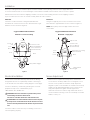
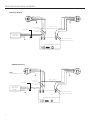
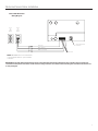
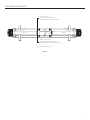
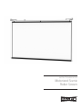
INSTRUCTION BOOK FOR
Motorized Scenic
Roller Screen
Important Safety Instructions
When using your video equipment, basic safety precautions
should always be followed, including the following:
1.
Read and understand all instructions before using.
2. Position the cord so that it will not be tripped over, pulled, or
contact hot surfaces.
3. If an extension cord is necessary, a cord with a current rating
at least equal to that of the appliance should be used. Cords
rated for less amperage than the appliance may overheat.
4. To reduce the risk of electric shock, do not disassemble this
appliance. Contact an authorized service dealer when repair
work is required. Incorrect reassembly can cause electric
shock when the appliance is used subsequently.
5. The use of an accessory attachment not recommended by
the manufacturer may cause a risk of fire, electric shock, or
injury to persons.
2
Installation
Before proceeding with the installation please read the installation and operating instructions thoroughly. Make sure
to recheck measurements of screen and hanger locations before installation. Area must be clear for screen to operate.
With all lid sections removed from shipping container, remove the screws holding the frame to the shipping container
(2 per cross brace). The screen can now be carefully lifted out of the container.
Method A
The frame can be mounted to ceiling with 5/16" diameter
threaded rods. Level frame from front to back and left to right.
Mount from all cross braces (Figure 1).
Method B
Hang from a pipe (fly the screen). Level frame from front to
back and left to right. Mount from all cross braces (Figure. 2).
NOTE: Motor pulley must clear pipe. Chains must clear
motor tubes.
Suggested Method Of Installation
Suggested Method Of Installation
Method A – Secure To Ceiling
Method B – “Flying Pipe”
Ceiling
Ceiling
Secure To
Suit
Cross
Brace
Pipe To Suit
Chain To Suit
(6 Cross Braces)
(Not Furnished)
Secure To Suit
5/16" Threaded Rod
(6 Cross Braces)
(Not Furnished)
Front
Back
15"
Eye Bolts For Leveling
(Not Furnished)
Cross
Brace
Back
Front
Cable
Safety Switch Trigger
Safety Switch
Trigger
Figure 1
Figure 2
Electrical Installation
Screen Adjustment
Screen motors have been internally wired at Da-Lite. Wiring
designated “external” is completed by installer conforming to
local and national codes. Refer to wiring diagram on next page.
1. With screen in complete unrolled position, examine the
screen surface carefully. If fabric does not hang flat, loosen
the nuts on the eyebolts of the black clamps. Adjust the
wingnuts to pull or relax the fabric as needed. Several clamp
heights may be adjusted depending on the severity of the
hang. After adjustment, tighten the nuts against the
underside of the frame. Caution stage hands and others to
check area before lowering screen. Do not bump screen with
ladders, scenery, etc.
Check for satisfactory condition by operating the screen. Be
prepared to stop screen. Standard Duty Cycle:
1 MIN. 30 SEC. ON / 45 MIN. OFF.
CAUTION! Excessive continuous operation may cause
overheating and motors will shut off.
Let motors cool 10 to 15 minutes and continue test.
ATTENTION! Le fonctionnement continu et excessif peut
provoquer une surchauffe et l'arrêt du moteur. Laissez le
moteur refroidir pendant 10 à 15 minutes et poursuivez le
test.
Check the cables to make sure they are winding on the motor
and roller pulleys properly.
3
Motorized Scenic Roller Installation
120V Wiring Diagram
White - (Common)
Red - (Up)
Black - (Down)
Green - (Ground)
Brown - Out Of
Controller
Red - Out Of
Controller
Safety Switch
White - (Common)
Black - (Hot)
Green - (Ground)
White - (Common)
Red - (Up)
Black - (Down)
White
BLACK
Power Input
120VAC / 60HZ
White - (Common)
Red - (Up)
Black - (Down)
Green - (Ground)
Red - Out Of Controller
Brown - Out Of Controller
240V Wiring Diagram
NOTES:
1. FUSE RATED 15A - 250VAC
Brown - Out
Of Controller
Red - Out Of
Controller
Safety Switch
Blue - (Common)
Brown - (Hot)
Green/Yellow (Ground)
Black
Power Input
240VAC / 50HZ
3.6 AMPS
Blue - (Common)
Black - (Up)
Brown - (Down)
Green/Yellow (Ground)
Blue - (Common)
Black - (Up)
Brown - (Down)
Green/Yellow - (Ground)
Blue - (Common)
Black - (Up)
Brown - (Down)
WhiteBlack
Red - Out Of Controller
Brown - Out Of Controller
4
Motorized Scenic Roller Installation
120V / 240V Wall Switch
Wiring Diagram
Front
Of
Wall
Switch
Back
Of
Wall
Switch
UP
STOP
DOWN
Optional RF Remote
Connection
Red - (Up)
Black - (Down)
White - (Common)
Not Used
NOTE: 20-24AWG wire recommended for
connecting wall switch to sychronization
controller.
IMPORTANT! The wall switch terminal block can be connected inside the wiring compartment. The controller does not need to be
removed from the junction box unless an RF remote is being connected. Use caution when removing the controller from the box as it
is easily damaged.
5
Limit Switch Adjustment
The stop positions of the screen are preset at the factory. If adjustments are necessary, the limit switch screws located at the end
of each motor can adjust the stop positions. Use a 5/32" hex key or a flat screwdriver. Adjustments should be made in small increments
by turning the adjustment screws a half turn at a time. Refer to figure 3.
Setting The "Down" Limit Position.
Setting The "Up" Limit Position.
Screen Drops Too Far:
Screen Travels Up Too Far:
Left motor (as viewed from audience side): Turn the white limit
switch screw clockwise to decrease the amount of fabric drop.
Left motor (as viewed from audience side): Turn the yellow limit
switch screw clockwise to decrease the amount of travel.
Right motor (as viewed from audience side): Turn the yellow limit
switch screw clockwise to decrease the amount of fabric drop.
Right motor (as viewed from audience side): Turn the white limit
switch screw clockwise to decrease the amount of travel.
After adjusting the limit screws on both motors, run the screen
down to test the stop position. Repeat until the desired position
is set.
After adjusting the limit screws on both motors, run the screen
up to test the stop position. If the screen travels up too far, the
safety stop switch will be activated and all power to the motors
will be shut off. You will have to deactivate the switch by hand. To
do this, push down on the switch trigger (see Figure 1) to release
the switch and have someone run the screen down. This safety
switch is to prevent the screen from traveling too far and binding
the motors should the motor limit switches fail.
Screen Does Not Drop Enough:
Left motor (as viewed from audience side): Turn the white
limit switch screw counterclockwise to increase the amount
of fabric drop.
Right motor (as viewed from audience side): Turn the yellow
limit switch screw counterclockwise to increase the amount
of fabric drop.
After adjusting the limit screws on both motors, run the screen
down to test the stop position. Repeat until the desired position
is set. Do not adjust for more drop than what was ordered. At
least 1-1/2 wraps of fabric must remain on the roller.
6
Screen Does Not Travel Up Far Enough:
Left motor (as viewed from audience side): Turn the yellow limit
switch screw counterclockwise to increase the amount of travel.
Right motor (as viewed from audience side): Turn the white limit
switch screw counterclockwise to increase the amount of travel.
After adjusting the limit screws on both motors, run the
screen up to test the stop position. Repeat until the desired
position is set.
Limit Switch Adjustment
Yellow - Up Limit
Clockwise = Less Up Travel
Counterclockwise = More Up Travel
Motor 1
Motor 2
White - Down Limit
Clockwise = Less Down Travel
Counterclockwise = More Down Travel
Top View - Audience Side
Figure 3
7
LIMITED ONE YEAR WARRANTY ON DA-LITE PRESENTATION PRODUCTS
Milestone AV Technologies LLC warrants certain Da-Lite branded products to the original purchaser only, to be free from defects in
materials and workmanship for a period of one (1) year from the date of purchase by the original purchaser; provided they are properly
operated according to Da-Lite's instructions and are not damaged due to improper handling or treatment after shipment from the
factory.
This warranty does not apply to equipment showing evidence of misuse, abuse or accidental damage, or which has been tampered
with or repaired by a person other than authorized Da‑Lite personnel.
Da-Lite’s sole obligation under this warranty shall be to repair or to replace (at Da-Lite’s option) the defective part of the merchandise.
Returns for service should be made to your Da-Lite dealer. If it is necessary for the dealer to return the screen or part to Da-Lite,
transportation expenses to and from Da-Lite are payable by the purchaser and Da-Lite is not responsible for damage in shipment.
To protect yourself against damage or loss in transit, insure the product and prepay all transportation expenses.
TO THE MAXIMUM EXTENT PERMITTED BY APPLICABLE LAW, THIS WARRANTY IS IN LIEU OF ALL OTHER WARRANTIES, EXPRESS
OR IMPLIED, INCLUDING WARRANTIES AS TO FITNESS FOR USE AND MERCHANTABILITY. Any implied warranties of fitness for use,
or merchantability, that may be mandated by statute or rule of law are limited to the one (1) year warranty period. This warranty gives
you specific legal rights, and you may also have other rights, which vary from state-to-state. TO THE MAXIMUM EXTENT PERMITTED
BY APPLICABLE LAW, NO LIABILITY IS ASSUMED FOR EXPENSES OR DAMAGES RESULTING FROM INTERRUPTION IN OPERATION
OF EQUIPMENT, OR FOR INCIDENTAL, DIRECT, OR CONSEQUENTIAL DAMAGES OF ANY NATURE.
In the event that there is a defect in materials or workmanship of a Da-Lite product, you may contact our Sales Partners at PO Box 137,
Warsaw, IN 46581-0137, (574) 267-8101, (800) 622-3737.
IMPORTANT: THIS WARRANTY SHALL NOT BE VALID AND DA-LITE BRANDED PRODUCTS SHALL NOT BE BOUND BY THIS
WARRANTY IF THE PRODUCT IS NOT OPERATED IN ACCORDANCE WITH THE DA-LITE WRITTEN INSTRUCTIONS.
Keep your sales receipt to prove the date of purchase and your original ownership.
A Milestone AV Technologies Brand
3100 North Detroit Street
Warsaw, Indiana 46582
P: 574.267.8101 or 800.622.3737
F: 574.267.7804 or 877.325.4832
E: [email protected]
www.da-lite.com
DL–0278 (Rev. 1) 07.14
© 2014 Milestone AV Technologies LLC. Printed in U.S.A.
84222