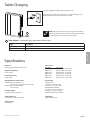
1
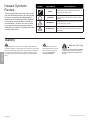
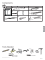
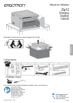
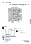
User's Guide
Tablet Charging Wall Mount 12
ENGLISH
For the latest User Installation Guide please visit: www.ergotron.com
User's Guide - English
Guía del usuario - Español
Manuel de l’utilisateur - Français
Gebruikersgids - Deutsch
Benutzerhandbuch - Nederlands
Guida per l’utente - Italiano
Användarhandbok - svenska
ユーザーガイド : 日本語
用户指南 : 汉语
888-61-070-G-02 rev. C • 01/14
1 of 17
Hazard Symbols
Review
Symbol
These symbols alert users of a safety condition that demands attention. All users should
be able to recognize and understand the
significance of the following Safety Hazards
if encountered on the product or within the
documentation. Children who are not able
to recognize and respond appropriately to
Safety Alerts should not use this product without adult supervision!
Signal Word
Level of Hazard
NOTE
A NOTE indicates important information that helps you
make better use of this product.
CAUTION
A CAUTION indicates either potential damage to
hardware or loss of data and tells you how to avoid the
problem.
WARNING
A WARNING indicates either potential for property damage, personal injury, or death.
ELECTRICAL
An Electrical indicates an impending electrical hazard
which, if not avoided, may result in personal injury, fire
and/or death.
ENGLISH
Safety
WARNING: Because surfaces vary widely and the ultimate
mounting method is out of Ergotron’s control, it is imperative
that you consult with appropriate engineering, architectural
or construction professional to ensure that your Ergotron
mounting solution is mounted properly to handle applied
loads.
CAUTION: Make sure the
wall mount bracket is level,
flush and snug to the wall
surface. DO NOT OVERTIGHTEN THE BOLTS.
< 44.4 lbs. (20.1 kg)
CAUTION: DO NOT EXCEED MAXIMUM
LISTED WEIGHT CAPACITY. SERIOUS
INJURY OR PROPERTY DAMAGE MAY
OCCUR!
888-61-070-G-02 rev. C • 01/14
2 of 17
Components
A
B
C
D
1x
1x
1
5x
1x
1x
4x
2
1/4”-20 x 2”
1x
3
5x
4x
M6 x 70mm
5/32”
ENGLISH
Tools Needed
Stud Finder
2
1
10mm
WOOD STUD
HOLLOW WALL
Ø 3/16" (5 mm)
Ø 1/2" (13 mm)
CONCRETE
Ø 3/8" (10 mm)
888-61-070-G-02 rev. C • 01/14
3 of 17
1 MOUNTING CONSIDERATIONS
Space Requirements:
When mounting to wood stud, at least one screw in the upper mounting
bracket must be installed in a stud (preferably the center hole).
35.3"
(900 mm)
6" (152 mm)
7"
11.8"
6.5”
(178 mm)
(300 mm)
(168 mm)
4” (102 mm)
6"
(151 mm)
3"
(74 mm)
Mounting
Holes
35.6"
32.75"
(905 mm)
ENGLISH
(831 mm)
Individual tablet or chromebook weight:
Individual dimensions (including cover):
< 11.4" (289 mm)
62”-68”
(158-173 cm)
Recommended Mounting Height Above Floor
< 3 lbs
< 8.5"
(1.36 kg)
(215 mm)
< 1"
(25 mm)
2
WOOD STUD
HOLLOW WALL
CONCRETE
5
8
888-61-070-G-02 rev. C • 01/14
4 of 17
WOOD STUD
HOLLOW WALL
a
First Choose a Hole Option:
The stud can be located at one of five mounting holes on the top bracket.
While the first option (center hole of bracket) is recommended, you should
consult with a construction professional to confirm which method is best
suited for your particular situation.
After you decide on a Hole Option, follow attachment instructions on the
following page.
Hole Option 1
RECOMMENDED
Center Hole in Stud
Hole Option 2
Hole Option 3
Hole Option 4
Hole Option 5
Extreme Right Hole in Stud
Middle Right Hole in Stud
Middle Left Hole in Stud
ENGLISH
Extreme Left Hole in Stud
888-61-070-G-02 rev. C • 01/14
5 of 17
WOOD STUD
HOLLOW WALL
b
Find stud and draw a mark.
c
Put a mark on the stud 62”-68” (158-173 cm)
from floor.
ENGLISH
62”-68”
(158-173 cm)
d
Place template on wall lining up the
chosen hole with the stud and the
mark 62”-68” (158-173 cm) from floor.
e
Secure template to wall.
62”-68”
(158-173 cm)
7
888-61-070-G-02 rev. C • 01/14
6 of 17
WOOD STUD
HOLLOW WALL
f
1. Drill the three holes for the top bracket that correspond with the hole option determined on previous page.
2. Drill the bottom two holes.
NOTE: Use the Ø 3/16” (5 mm) drill bit when drilling directly into the wood stud.
Use the Ø 1/2” (13 mm) drill bit when drilling into the hollow wall for the anchors.
Use hollow wall anchors where ever a screw does not get inserted directly into the
wood stud.
WOOD STUD
10mm
Ø 3/16"
(5 mm)
M6 x 70mm
1x
HOLLOW WALL
Ø 1/2"
(13 mm)
5/32”
ENGLISH
1/4”-20 x 2”
62”-68”
(158-173 cm)
1
g
h
2
3
4
Insert anchors then attach bracket to wall according to the hole
option determined on previous page. Verify wall bracket is level
before tightening screws.
9
888-61-070-G-02 rev. C • 01/14
7 of 17
CONCRETE
a
b
Put a mark on the stud 62”-68”
(158-173 cm) from floor.
Attach template to the wall
lining up the chosen mounting
holes with the mark 62”-68”
(158-173 cm) from floor.
60”-66"
(1524-1676 mm)
60”-66"
(1524-1676 mm)
c
d
Drll the top 3 holes, then the bottom two holes.
ENGLISH
Ø 3/8" (10 mm)
3-1/8"
(80 mm)
WARNING:
Mounting holes must be at least 3-1/8” (80mm)
deep and must be located within solid concrete,
not mortar or covering material. If you drill into
an area of concrete that is not solid, reposition
mounting holes until both anchors can be fully
inserted into solid concrete!
62”-68”
(158-173 cm)
e
Insert anchors into holes, then attach mounting bracket.
5x
M6 x 70mm
10mm
5x
WARNING:
Anchors that are not fully set in solid concrete
will not support the applied load resulting in
an unstable, unsafe condition which could lead
to personal injury and/or property damage.
Consult a construction professional if you have
any doubt about what this means in regard to
your particular situation.
9
888-61-070-G-02 rev. C • 01/14
8 of 17
3
Hang unit onto top bracket.
Warning: 2 people are required to lift
this product.
4
a. Remove two screws on left side. Save screws for reattaching cover.
b. Unlock door and turn wing knob 90° clockwise.
a
b
ENGLISH
5
a. Open door and remove these 3 screws. Save screws for reattaching cover.
b. Remove left cover
a
b
888-61-070-G-02 rev. C • 01/14
9 of 17
6
a. Secure unit to wall by inserting screw through back wall and into bottom right wall anchor.
b. Close door, then insert screw through back wall and into bottom left wall anchor.
WOOD STUD
HOLLOW WALL
CONCRETE
5x
5/32”
2x
1/4”-20 x 2”
M6 x 70mm
10mm
a
b
b
ENGLISH
a
888-61-070-G-02 rev. C • 01/14
10 of 17
7
a. Plug in all the tablet power cables into the outlets inside.
b. Route cables through the access holes.
c. Open door an pull cables through the access holes.
a
b
ENGLISH
c
888-61-070-G-02 rev. C • 01/14
11 of 17
Pull out tablet tray and insert tablet.
NOTE: Tablet should be positioned so power plug is at top or left side.
ENGLISH
8
9
a. Pull cable clip off of tablet slot and route cable through clip, then reattach cable clip.
NOTE: Leave enough slack in cable to plug into tablet.
b. Plug tablet cables into tablets.
NOTE: When tablet is removed, store unconnected cable in the appropriate tablet slot.
a
b
888-61-070-G-02 rev. C • 01/14
12 of 17
10
Tie up excess cable with velcro cable ties.
NOTE: Keep cables away from
power system components that
might get hot during operation.
ENGLISH
11
a. Attach left cover with 2 screws saved from removal of cover.
b. Open door and attach 3 inside screws saved from removal of left cover
a
b
888-61-070-G-02 rev. C • 01/14
13 of 17
12
ENGLISH
a
13
a. Close door.
b. Lock door by rotating wing knob 90° counterclockwise.
b
Plug power cable into bottom access and then into wall outlet to start charging.
888-61-070-G-02 rev. C • 01/14
14 of 17
Tablet Charging
To begin charging the tablets, plug in the power cord.
The power cord is used to turn the power on and off. Charging occurs
whenever the power cord is connected to an outlet.
LED
NOTE: The power cord acts as the connect/disconnect device
switching power off and on. The socket outlet shall be installed
near the equipment and shall be easily accessible.
Power Indicator – Communicates charge status with the following signals:
Light
Description
Off
No power to the module.
On - solid
Tablets or Chromebooks are charging.
ENGLISH
Specifications
Dimensions
26.4”W x 35.6”H x 5.9”D (669 x 905 x 151 mm)
Weight (w/o equipment)
64.5 lbs (29.3 kg)
Rated weight capacity
44.4 lb (20.1 kg)
Maximum tablet or chromebook size
Individual dimensions (including cover):
up to 11.4” H x 8.5” W x 1.0” D (290 x 216 x 25 mm)
Individual tablet or chromebook weight:
up to 3 lb (1.4 kg)
Power system
Part number
DM12-1005-1
DM12-1005-2
DM12-1005-3
DM12-1005-4
DM12-1005-5
DM12-1005-6
Power System
Input: 100-120V~, 12A, 50/60 Hz
Input: 220-240V~, 8A, 50/60 Hz
Input: 220-240V~, 8A, 50/60 Hz
Input: 220-240V~, 8A, 50/60 Hz
Input: 220-240V~, 8A, 50/60 Hz
Input: 100-120V~, 12A, 50/60 Hz
Cooling/ventilation
One 12V DC continuous operation fan
Environmental
Temperature range:
Operating 0° to 30°C (32° to 86°F)
Storage -40° to 60°C (-40° to 140°F)
Relative humidity (maximum):
Operating 10%–90% (non condensing)
Storage 5%–95% (non condensing)
Altitude (maximum): 2000 m (6,562 ft)
Shipping dimensions
40.9” x 28.9” x 8.4” (1040 x 735 x 214 mm)
Compatibility:
Tablets and chromebooks
Shipping weight
77 lb (34.9 kg)
888-61-070-G-02 rev. C • 01/14
15 of 17
Cleaning and Maintenance
Equipment Electric Safety
There are specific risks associated with the use of equipment having power cables. You must be aware of, and avoid these risks when this product is located in
close proximity to children.
WARNING: Failure to observe the following Electrical Safety notices can result in fire or death by electric shock.
Electrical cables can be hazardous. Misuse can result in fire or death by electrical shock.
• Double Pole / Neutral Fusing
• Inspect power cables thoroughly before each use.
• Do not use cables that are damaged.
• Insert the plug completely into the outlet.
• Grasp the plug to remove from the outlet.
• Do not unplug by pulling on the cable.
• Do not use excessive force to make connections.
• Do not plug the cable into an extension cable.
• Do not remove, bend or modify any metal prongs or pins of cable.
• Do not drive, drag or place objects over the cable.
• Do not walk on the cable.
• Avoid overheating. Uncoil the cable and do not cover it with any material.
• Do not run cable through doorways, holes in ceilings, walls or floors.
Keep this product away from water.
• Do not use it when wet.
• Do not place this product in close proximity to flammable liquids or gases.
ENGLISH
This product is intended for use only with loading as indicated. Use with loads greater than indicated may result in instability causing possible injury.
The power cord acts as the connect/disconnect device switching power off and on. The socket outlet shall be installed near the equipment and shall be easily
accessible.
CAUTION: Changes or Modifications not expressly approved by Ergotron could void the user’s authority to operate the equipment.
Use Safety
There are specific risks associated with the use of this product (for charging or storage). You must be aware of, and avoid these risks when this product is
located in close proximity to children.
WARNING: Failure to observe the following Use Safety notices may result in serious personal injury or equipment damage.
Only Adults should use this product.
• Do not allow anyone to climb or hang on this product.
• Do not block the fans and vent openings. To prevent overheating, leave at least 127 mm (4-inch) clearance around
fans and vents.
This product is designed to be used indoors only.
• Do not use this product to store equipment other than what has been noted in this guide.
• Do not use this product to store liquids or cleaning supplies.
• Do not place heavy objects on this product.
– The maximum weight capacity is 44.4 lbs (20.1 kg).
This device complies with Part 15 of the FCC Rules.
Operation is subject to the following two
conditions: 1) This device may not cause harmful
interference. 2) This device must accept any
interference received, including interference that
may cause undesired operation.
CAN ICES-3(A) / NMB-3(A).
888-61-070-G-02 rev. C • 01/14
16 of 17
Service and Warranty
For local customer care phone numbers visit: http://contact.ergotron.com
NOTE: When contacting customer service, reference the serial number.
www.ergotron.com
MADE IN CN
12-345-678
1234567-1234
ENGLISH
888-61-070-G-02 rev. C • 01/14
17 of 17