1
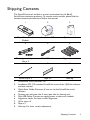
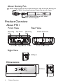
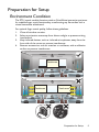
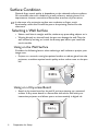
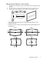
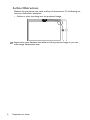
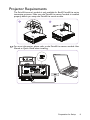
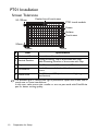
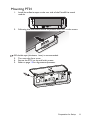
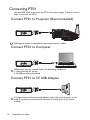
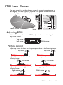
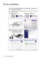
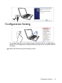
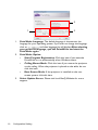
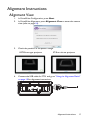
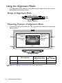
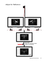
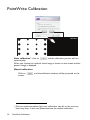
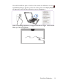
PT01 User Manual
Version: 1
Keep this user manual for future references.
Table of contents
Shipping Contents........ 3
Product Overview........ 4
About PT01 ...............................................4
Dimensions ................................................4
Preparation for Setup.. 5
Environment Condition ...........................5
Surface Condition .....................................6
Projector Requirements..........................9
PT01 Installation......................................10
Connecting PT01 ....................................12
PT01 Laser Curtain ... 13
Adjusting PT01.........................................13
Driver Installation ...... 14
Configuration
Setting ......................... 15
Alignment
Instructions................. 17
Alignment View .......................................17
Using the Alignment Masks...................18
PointWrite
Calibration .................. 20
Specifications.............. 22
2
Table of contents
Shipping Contents
The PointWrite touch module is a touch transmitter for the BenQ
PointWrite interactive projector. To use the touch module, please find the
standard accessories below and follow this manual.
1
2
3
Digital
Quick Projector
Start
Guid
e
1.
2.
3.
4.
5.
6.
7.
8.
9.
PointWrite Touch
Module
4
Installation CD
Quick manual
5
6
Dummy pen with pen
nibs x 2
7
Mini USB cable
Alignment masks
8
9
Wrist strip x 2
Tape x 2
Hex key
PointWrite Touch Module PT01
Installation CD: CD contains PointWrite touch driver, QWrite software
and user manual.
Quick Start Guide: Shortcut of how to use the PointWrite touch
solution.
Dummy pen with pen nibs: 2 extra pen nibs for dummy pen.
Mini USB Cable: Connect to supply power to the touch module.
Alignment masks: For laser curtain alignment.
Wrist strip x 2
Tape x 2
Hex key: For laser curtain adjustment
Shipping Contents
3
About Dummy Pen
When replacing the pen nib on the dummy pen, take it from the dummy pen.
For better touch performance, keep the pen nib clean.
When replacing the pen nib, take it
from the dummy pen.
Product Overview
About PT01
Front View
Mounting
hole
Top screw
Rear View
Mounting
hole
Left screw Right screw Cover
Attach tape area
Touch module head
Right View
USB port
Dimensions
58.09mm
178.85mm
4
Product Overview
40.10mm
Preparation for Setup
Environment Condition
The PT01 touch module functions with an PointWrite interactive projector
for scalable finger touch functionality, transforming any flat surface into a
virtual interactive whiteboard.
For optimal finger touch quality, follow these guidelines:
1.
2.
3.
4.
Close all window curtains.
Select a projection area away from direct sunlight to prevent writing
interference.
Keep infrared devices, such as: infrared microphones, away from the
front side of the screen to prevent interference.
Remove accessories, such as: watches or necklaces, with a reflective
surface to prevent interference.
Touch area
Touch area
Touch area
Preparation for Setup
5
Surface Condition
Optimal finger touch quality is dependent on the selected surface condition.
You can attach the touch module on a wall surface or existing board. It is
important to choose a smooth and flat surface area free of protrusions.
In the event of a projection surface not conducive to finger touch
functionality, select the PointWrite pen as the pointing method for the
classroom.
Selecting a Wall Surface
• Select a wall that is straight and flat, without any protruding objects on it.
• Writing directly on the wall with the pen can damage the wall. Test the
wall surface by writing on it with the dummy pen before you install the
touch module.
Using on the Wall Surface
Consider the following factors when selecting a wall surface to project your
image onto:
• Project on a smooth, semi-gloss painted surface to reduce glare from the
projector, to achieve optimal touch quality and to reduce wear on the pen
nib.
Using on a Dry-erase Board
• Attach a dry-erase board to the wall if you’re projecting on a textured
surface. A dry-erase board is a flat surface that works well with your
interactive projector and allows you to write smoothly in digital ink.
6
Preparation for Setup
Measuring the Flatness of the Surface
1.
2.
3.
Place a six-foot carpenter’s level horizontally across the projection area
(board).
Locate the point on the level furthest away from the projection area.
Measure the surface flatness on both sides of the projection area.
• Overall finger touch performance is influenced by the flatness of the
projection surface.
• A flatness variance of 2mm in any direction ensures optimal finger touch
performance.
<2mm
<2mm
<2mm
<2mm
Preparation for Setup
7
Surface Obstructions
Maintain the projection area clean and free of obstructions. The following are
common obstruction examples:
• Cables or wires that hang into the projected image.
Leave extra space between the cables and the projected image so you can
make image adjustments later.
8
Preparation for Setup
Projector Requirements
The PointWrite touch module is only available for BenQ PointWrite series
interactive projector. Make sure the PointWrite camera module is installed
properly before you setup the PointWrite touch module.
1
2
For more information, please refer to the PointWrite camera module User
Manual or Quick Guide when installing.
Preparation for Setup
9
PT01 Installation
Screen Tolerance
50-100mm
Center line of touch area
PT01 touch module
Frame
Surface
Touch area
50mm
50mm
#
Item
50mm
Specification
1 Horizontal Position Center Line of beamed screen.
Ceiling Mounting: Top of the screen with Gap.
2 Vertical Position
Table Mounting: Bottom of the screen with Gap.
3 Gap
Min: 50mm, max: 100mm, normal: 70mm
Head of laser module should be face to touch
4 Orientation
screen.
Min: 65”, max: 100” (without external lighting
5 Touch Area
interference)
The ambient light or directly sun light is possible to impact the screen size of
touch area or cause interference.
In this case, make screen size smaller or turn to pen mode with PointWrite
pen for better writing quality.
10
Preparation for Setup
Mounting PT01
1.
Install the adhesive tape on the rear side of the PointWrite touch
module.
2.
Following the instructions above to position the PT01 on the screen.
3M double tape (thickness: 1mm) is recommended.
3. Turn over the front cover.
4. Secure the PT01 to the wall with screws.
5. Refer to page 13 for alignment adjustment.
Preparation for Setup
11
Connecting PT01
Use the USB cable to connect the PT01 for power supply. There are three
ways to connect the PT01.
Connect PT01 to Projector (Recommended)
USB type-A power is available for selected projector model.
Connect PT01 to Computer
USB power may be unstable under the following conditions:
1. disconnecting AC power
2. all USB ports are populated
Connect PT01 to 5V USB Adapter
It is important to disconnect the adapter when the touch function is not
used. A continuous transmit will decrease the lamp time of the touch
module.
12
Preparation for Setup
PT01 Laser Curtain
The laser curtain is a perfect plane to cover the screen in max fan angle of
180 degrees. The laser curtain is required to be parallel to the surface with
the optimal gap for the effective finger touch performance.
Screen
board
Laser curtain
Laser
curtain
Gap
Height
Adjusting PT01
To have the best performance of PT01, adjust the laser curtain using a hex
key on the screws.
Top screw
Left screw
Right screw
Pitching control
Adjust top screw, the laser curtain goes up and down as the following image.
Top screw
Top screw
Adjust left screw, the left side of laser curtain goes up and down as the
following image.
Left screw
Left screw
Adjust right screw, the right side of laser curtain goes up and down as the
following image.
Right screw
Right screw
PT01 Laser Curtain
13
Driver Installation
Use the PointWrite driver in the PT01 CD to enable the
finger touch function.
The CD in the PointWrite pen kit does not contain the finger
touch function.
PointWrite Pen kit
PT01 touch module kit
Pen Mode
Finger Mode
Disconnect the USB cable
from PointWrite camera
module when installing.
14
Driver Installation
Pen Mode
Finger Mode
Configuration Setting
To use the PointWrite, the proper setting of the PointWrite configuration is
needed. The Configuration setting window will help you to set up PointWrite
correctly.
Select Pen Mode during the setting process.
Configuration Setting
15
2
1
1.
2.
3.
16
3
PointWrite Language: The default language is the same as the
language for your operating system. If you want to change the language,
click on
and then language list will display. After selecting
your preferred language, quit the PointWrite and start the
PointWrite again.
PointWrite Option:
•
Start Program Registration: Click this item if you want the
PointWrite to run automatically when Windows starts.
•
Ceiling Mount Mode: Click this item if you mount the projector
on the ceiling. When the projector is placed on the table, do not
click this item.
•
Rear Screen Mode: If the projector is installed on the rear
screen system, click this item.
Select Update Server: Please visit local BenQ Website for more
support.
Configuration Setting
Alignment Instructions
Alignment View
1.
2.
In PointWrite Configuration, press Next.
In PointWrite Alignment, press Alignment View to enter the camera
view (refer to page 18).
3.
Check the position of the pattern image.
UST-Mirrot type projector
4.
ST-Short throw projector
Connect the USB cable for PT01 and go to "Using the Alignment Masks"
on page 18 for alignment instructions.
Alignment Instructions
17
Using the Alignment Masks
The alignment masks help you to find the optimal height of the laser curtain
and optimal touch performance.
Shape of Alignment Mark
Lower reflector
5mm
5mm
Higher reflector
Mounting Position of Alignment Mark
In the camera view of PointWrite, The alignment mark reflector is shown like
below picture.
Mask 2
Reflection of
mask 3
Reflection of
mask 4
Reflection of
mask 1
Reflection of
mask 2
Mask 4
Mask 1
Mask 3
Ceiling Mounting
Description
Mask 1, 2 Upper side of the screen
Mask 3, 4 Bottom side of the scren
Best reflection in
High of
alignment view laser curtain
2 points
3 or 1 points
Refer to "Alignment Instructions" for more information.
18
Alignment Instructions
< 5mm
5 - 10mm
Adjust for Reflection
Left screw
Right screw
Left screw
Right screw
Top screw
Adjust the reflection laser
curtain horizontally
OK
Alignment Instructions
19
PointWrite Calibration
Auto calibration1: click on
automatically.
and the calibration process will run
When you choose this method, white image is shown on the screen and the
pattern image is displayed.
Manual calibration:
Click on
screen.
1.
20
and the calibration window will be projected on the
Due to excessive ambient light, auto calibration may fail or the accuracy
level may drop. In this case, please execute the manual calibration.
PointWrite Calibration
Use the PointWrite pen to click on the center of calibration cursor
immediately after it appears. Then the next cursor will display. Repeat
this process until the last calibration cursor disappears.
After completing calibration, change the mode to Finger Touch Mode.
Now you can use QWrite.
PointWrite Calibration
21
Specifications
Touch module
Model Name
Operating Voltage
Power Consumption
USB Type (Power)
Power Source
Wavelength
Fan Angle
Rolling Control Range
Pitch Control Range
Safety
Dimension
Weight
PT01
4.7~5.2V
Max 180mA
Mini USB B type
Power via USB connector or 5V adaptor
850nm ± 10nm
Max : 180° (1 laser beam)
Max 4°
Max 3.5°
Class 1
178.85 x 58.09 x 40.10mm
152g (with cover)
General function
Camera Type
Multi Pen Supported
Response Time
Refresh Rate
Calibration
Dual screen Calibration
USB Cable Distance
22
Specifications
PointWrite series camera module
Up to 4 touch points (Pen/Finger)
0.016 sec
60 Frames/sec
Auto / Manual16 points
Yes
Max 15meter (5meter USB cable + repeater)