1
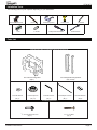
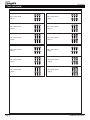
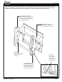
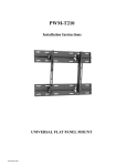
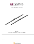
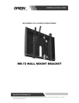
PFW 6870
Video Wall Pop-Out Module
INSTALLATION INSTRUCTIONS
9541-000-Z00-01
PFW 6870
Contents
Weight Limit............................................................................................................................................................... 2
Warning Statements.................................................................................................................................................. 2
Installation Tools........................................................................................................................................................ 3
Parts List................................................................................................................................................................... 3
Features.................................................................................................................................................................... 5
Installing the Mount................................................................................................................................................... 6
Introduction................................................................................................................................................... 6
Installing Optional Model Specific Spacers............................................................................................................... 8
Installing the Mounting Brackets............................................................................................................................... 9
Selecting the Mounting Hardware................................................................................................................ 9
Universal Washer Installation..................................................................................................................... 10
Universal Spacer Installation...................................................................................................................... 10
Attaching the Mounting Brackets to the Flat-Panel.................................................................................... 11
Mounting the Flat-Panel.......................................................................................................................................... 11
Attaching the Flat-Panel to the Mount........................................................................................................ 11
Locking Safety Screw Installation............................................................................................................... 12
Post-Installation Adjustments..................................................................................................................... 12
Maintenance and Servicing........................................................................................................................ 15
Technical Specifications.......................................................................................................................................... 16
Warranty.................................................................................................................................................................. 17
Weight Limit
Maximum Flat-panel Weight:
73 kg
THE WALL STRUCTURE MUST BE CAPABLE OF
SUPPORTING AT LEAST FIVE TIMES THE WEIGHT OF
THE FLAT-PANEL. IF NOT, THE WALL STRUCTURE MUST
BE REINFORCED.
Warning Statements
PRIOR TO THE INSTALLATION OF THIS PRODUCT, THE INSTALLATION INSTRUCTIONS MUST BE READ AND
COMPLETELY UNDERSTOOD. KEEP THESE INSTALLATION INSTRUCTIONS IN AN EASILY ACCESSIBLE LOCATION
FOR FUTURE REFERENCE.
PROPER INSTALLATION PROCEDURE BY A QUALIFIED SERVICE TECHNICIAN MUST BE FOLLOWED, AS OUTLINED
IN THESE INSTALLATION INSTRUCTIONS. FAILURE TO DO SO COULD RESULT IN PROPERTY DAMAGE, SERIOUS
PERSONAL INJURY, OR EVEN DEATH.
SAFETY MEASURES MUST BE PRACTICED AT ALL TIMES DURING THE ASSEMBLY OF THIS PRODUCT. USE
PROPER SAFETY EQUIPMENT AND TOOLS FOR THE ASSEMBLY PROCEDURE TO PREVENT PERSONAL INJURY.
VOGEL'S DOES NOT WARRANT AGAINST DAMAGE CAUSED BY THE USE OF ANY VOGEL'S PRODUCT FOR
PURPOSES OTHER THAN THOSE FOR WHICH IT WAS DESIGNED OR DAMAGE CAUSED BY UNAUTHORIZED
ATTACHMENTS OR MODIFICATIONS, AND IS NOT RESPONSIBLE FOR ANY DAMAGES, CLAIMS, DEMANDS, SUITS,
ACTIONS OR CAUSES OF ACTION OF WHATEVER KIND RESULTING FROM, ARISING OUT OF OR IN ANY MANNER
RELATING TO ANY SUCH USE, ATTACHMENTS OR MODIFICATIONS.
At least two qualified people should perform the assembly procedure. Personal injury and/or property damage can result
from dropping or mishandling the flat-panel.
If mounting to wall studs or ceiling studs, make sure that the mounting screws are anchored into the center of the wall studs
or ceiling studs. Use of an edge-to-edge stud finder is recommended.
It is recommended that a maximum of ⅝˝ plaster board be used when mounting to wooden studs.
Be aware of the mounting environment. If drilling and/or cutting into the mounting surface, always make sure that there
are no electrical wires in wall. Cutting or drilling into an electrical line may cause serious personal injury.
Make sure there are no water or natural gas lines inside the wall where the mount is to be located. Cutting or drilling into a
water or gas line may cause severe property damage or personal injury.
This product is intended for indoor use only. Use of this product outdoors could lead to product failure and/or serious
personal injury.
Do not install near sources of high heat. Do not install on a structure that is prone to vibration, movement or chance of
impact.
Page 2
Installation Instructions
PFW 6870
Installation Tools
The following tools may be required depending on your installation.
Electronic Stud Finder
Pencil
Protective Eyewear
½˝ Socket
Level
1/4˝ Drill Bit
Portable Drill
Socket Wrench
Phillips Head Screwdriver
Parts List
PFW 6870 Video Wall Pop-Out Module Assembly Components
One-Latch Mounting Base
(Qty 1)
5/16˝ Flat Washers
(Qty 4)
Universal Spacers
(Qty 12)
Left and Right Mounting Bracket
(Qty 1 Each)
3/16" Allen Wrench
(Qty 1)
Thread Depth Indicator
(Qty 1)
Universal Washers
(Qty 6)
Pro Mounting Hardware
5
/16˝
Concrete Wedge Anchors
(Qty 4)
Installation Instructions
5
/16˝
x 3˝ Lag Bolts
(Qty 4)
Page 3
PFW 6870
Parts List (cont’d)
Mounting Hardware
M4 x 12mm Screw
(Qty 6)
M6 x 12mm Screw
(Qty 6)
M4 x 16mm Screw
(Qty 6)
M6 x 16mm Screw
(Qty 6)
M4 x 25mm Screw
(Qty 6)
M6 x 25mm Screw
(Qty 6)
M5 x 12mm Screw
(Qty 6)
M8 x 12mm Screw
(Qty 6)
M5 x 16mm Screw
(Qty 6)
M8 x 16mm Screw
(Qty 6)
M5 x 25mm Screw
(Qty 6)
M8 x 25mm Screw
(Qty 6)
Page 4
Installation Instructions
PFW 6870
Features
The PFW6870 Video Wall Pop-Out Module is a customizable video wall mounting system featuring multi-monitor
stacking, open design, custom spacers and scissor mount extension. It has an extending scissor mount for easy
installation, cable management and servicing. Spacers are custom designed for specific flat-panels.
Post-Installation Adjustments
Patent-pending leveling, tilt and in-out
adjustment knobs make it easier than
ever to flush and level the flat-panels
for a seamless video wall.
Cable/Electrical Access
Allows for easy cable access and
power distribution installations.
Kickstand
Prop up the flat-panel with
the kickstand for easy
maintenance.
Spring Lock
Simply push the
mounting rails in
to lock or unlock
the mount from the
closed position.
Locking Safety Screws
Prevent the flat-panel from
being removed or dislodged
from the mount. Use an
optional Lock-It™ security
barrel for added protection.
Installation Instructions
Page 5
Installalation
PFW 6870
Introduction
Directional Mounting Arrow
The Directional Mounting Arrow stamped into the
PFW 6870 mount indicates which edge is the top.
Mounting Safety
Two people are recommended to install the
mount.
Step 1
You must secure the mount to two (2) wall studs
with four (4) lag bolts (2 lag bolts for each stud
found).
1) Use a stud finder to determine the exact center of
wall studs in the vicinity of the mount.
2) Use a pencil to mark the exact center of each of the
wall studs.
Step 2
Two people are recommended for this step; one
person to level the mount and another person to
mark the wall stud location.
1) Place the mount against the wall in the desired
viewing location.
2) Adjust the mount to align the mount slots in the
mount with the center of the wall studs.
3) Level the mount.
4) Use a pencil to mark the upper right mounting
location along the center of the wall stud.
Step 3
Drill a “pilot hole” in the center of the upper right mark
using a ¼″ drill bit and power drill.
(Only use a ¼˝ drill bit when drilling pilot holes.)
Page 6
Installation Instructions
PFW 6870
Installalation
Step 4
1) Place the mount against the wall and align it with the
pilot hole.
2) Insert one (1) 5/16˝ x 3˝ lag bolt and one (1) 5/16˝
washer into the upper right pilot hole.
3) Use a socket wrench and a ½˝ socket to tighten the
lag bolt.
Do not overtighten the lag bolt.
Step 5
1) Level the mount.
2) Use a pencil to mark the remaining four (4)
mounting locations along the center of each wall
stud.
Step 6
Two people are recommended for this step; one
person to level the mount and another person to
drill the pilot holes.
Drill a “pilot hole” in the center of each of the marks with
a power drill and a ¼″ drill bit.
Only use ¼″ drill bit when drilling the pilot holes.
Step 7
1) Insert one (1) 5/16″ x 3″ lag bolt and one (1) 5/16″
washer into each pilot hole
2) Tighten all lag bolts using a socket wrench and ½″
socket.
Do not overtighten the lag bolts when attaching
the mount to the wall. Improper installation may
result in personal injury or property damage.
If you are using OPTIONAL model specific spacers,
proceed to the "Installing Optional Model Specific
Spacers" on page 8.
If not, proceed to “Installing the Mounting Bracket”
on page 9.
Installation Instructions
Page 7
Installing OPTIONAL Model Specific Spacers
PFW 6870
PFW 6870’s dedicated flat-panel spacers are engineered
with the knowledge that aligning each flat-panel on a large
wall is time consuming and costly.These model-specific
spacers are available for most flat-panels, which significantly
reduces the installation time. (Call Customer Service to
inquire about model specific spacers.)
Step 1
This spacer is shown for illustration purposes only.
Your spacer may look different depending on the
display model you are installing.
1) Once your PFW 6870 is mounted in the desired
location and is level, align your spacer to the top left
or right (depending on your install direction) corner
register tabs of your mount.
You may use commercially available hardware to secure the spacer to the wall during installation
(depending on the wall material). You may utilize the
same spacer for multiple PFW 6870 installations.
Register Tabs
Register Tabs
Step 2
Multiple PFW 6870 mounts can be installed using model specific spacers. Simply repeat step one when installing
each of the surrounding PFW 6870 mounts. Use one spacer for each 2x2 installation by mounting it to the wall, or
utilize the same spacer as many times needed to complete an unlimited PFW 6870 video wall pop-out module.
1. Make sure the spacer is plumb and level and mark each corner where the PFW 6870 will be mounted (or
secure to the wall). It is best to start from the bottom corner and work your way up.
2. Install the second mount working in a horizontal direction.
3. Ensure that the mount remains plumb and level.
4. Repeat this step for each mount horizontally
5. To install multiple rows, place spacer between previously installed PFW 6870s on the bottom row. Make sure
the spacer is plumb and level, mark the corners (or secure to the wall) to be sure of where the PFW 6870
should be and secure your mount to the wall.
Start
Page 8
Installation Instructions
PFW 6870
Installing the Mounting Brackets
Selecting the Mounting Hardware
1) Insert a small straw or toothpick into the threaded
inserts found on the back of the flat-panel.
2) Use a pencil to mark the depth of the threaded
insert on the small straw or toothpick.
3) Mark the straw or toothpick 1/8” above the depth of
the threaded insert, as shown in Figure 1.
4) Insert the small straw or toothpick into the remaining
threaded inserts to compare and verify their depth
using the straw or toothpick’s 1/8” allowance mark.
5) Locate the correct diameter screw for the threaded
insert.
If the screw you selected is longer than the 1/8”
allowance mark on the small straw or toothpick,
as shown in Figure 2 and Figure 3, do not use
this screw. The screw length must not bypass the
mark.
Marking the 1/8”
Allowance
6) Test each size of the screws provided.
The correct screws should thread easily into the
mounting point and not pull out when tension is
applied.
Small Straw or Toothpick
Go to “Griplate™ Washer Installation” on page 10
Small Straw
or Toothpick
Depth Plus 1/8” Allowance
Mark
Installation Instructions
Small Straw
or Toothpick
Depth Plus 1/8” Allowance
Mark
Page 9
PFW 6870
Installing the Mounting Bracket (cont’d)
Universal Washer Installation
Vogel's’ Universal Washers are designed to
accommodate the various M4, M5, M6 and M8 hole
sizes required by flat-panels.
M8
M5, M6
M4
Do not place excessive pressure on the back of
the flat-panel, as this may damage your flat-panel.
The Universal Washer must be installed between
the head of the mounting screw and the mounting
bracket as shown.
Does your flat-panel have:
●● Recessed mount points?
●● Uneven mount points?
●● A curved back?
●● Any obstruction near the mount point?
If Yes, you must install Universal Spacers. Remove the
mounting brackets, Universal Washers, and mounting
screws from the back of the flat-panel. Proceed to the
“Universal Spacer Installation” section.
If No, skip to the “Attaching the Mounting Bracket
to the Flat-Panel” section.
Universal Spacer Installation
Vogel's’ Universal Spacers allow you to attach the
mounting bracket to flat-panels which have recessed or
uneven mount points. Each Universal Spacer adds ¼˝
to the distance between the mounting bracket and your
flat-panel.
The Universal Spacers must be stacked and
oriented as shown.
The Universal Spacers must only be installed
between the mounting bracket and your flat-panel.
Proceed to the “Attaching the Mounting Bracket to
the Flat-Panel” section.
Mounting Screw
Universal Washer
Mounting Bracket
Flat-Panel
Universal Spacer
Mount Point
1˝
¼˝
The Universal Spacers
Fit M4, M5, M6 and M8 screw sizes.
Page 10
Installation Instructions
PFW 6870
Installing the Mounting Brackets (cont’d)
Attaching the Mounting Brackets to the Flat-Panel
This section presumes that you have read and
understood thes "Selecting the Proper Mounting
Hardware" section.
1) Place your flat-panel screen-side down on a soft, flat
surface.
2) Identify the number and location of the thread
inserts on the back of your flat-panel.
3) Aligning the holes on each mounting bracket with
the thread inserts on the back of your flat-panel.
4) Secure each mounting bracket to your flat-panel by
inserting a minimum of two (2) screws per bracket.
Do not overtighten the mounting hardware.
Make sure the directional arrows on the mounting
brackets are facing up.
Proceed to the “Mounting the Flat-Panel” below.
Mounting the Flat-Panel
Attaching the Flat-Panel to the Mount
Mounting bracket adjustments are factory pre-set
(see Note).
This section requires two people.
Do not release your flat-panel until you are certain
that top and bottom hooks of both mounting
brackets are securely seated on the upper and
lower mounting rails of the wall panel.
1) Raise the flat-panel past the top and bottom
mounting rails on the wall panel.
2) Slide the flat-panel down slowly, keeping it close to
the wall.
3) Engage the top and bottom mounting brackets to
the rails of the mount.
Installation Instructions
Note: These registers
must align prior to
installation.They are
factory set. Check
to determine proper
alignment
Page 11
PFW 6870
Locking Safety Screw Installation
The locking safety screws keep the flat-panel from
being accidently dislodged from the PFW 6870.
1) Locate the pre-installed security locking safety
screw at the bottom of each of the mounting
brackets.
2) Use the Allen key (supplied) to tighten the locking
safety screw.
Pre-installed Security
Locking Safety Screw
(1 per Bracket)
Do not overtighten the locking safety screws.
Proceed to the “Post-Installation Adjustments” below.
Post-Installation Adjustments
The PFW 6870 has a set of post-installation
adjustments on each mounting bracket (Figure 1).
See Note
Use Allen key (supplied) to fine-tune adjust.
See Note
Make sure the the locking safety screws are
loosened before making adjustments.
Note: Screws have a limited travel adjustment.
Do not overtighten or over adjust the screw to
avoid damage to threaded holes.
Figure 1
See Note
Move Inward
Left Control
Right Control
Move Outward
Left Control
Right Control
Page 12
Installation Instructions
Post-Installation Adjustments (cont'd)
PFW 6870
Tilt Left
Left Control
Right Control
Tilt Right
Left Control
Right Control
Tilt Up
Left Control
Right Control
Tilt Down (from tilted-up position)
Left Control
Right Control
Installation Instructions
Page 13
Post-Installation Adjustments (cont'd)
PFW 6870
Level Up
Left Control
Right Control
Level Down (from leveled up position)
Left Control
Right Control
Rotate Left
Left Control
Right Control
Rotate Right
Left Control
Right Control
Page 14
Installation Instructions
PFW 6870
flay
Maintenance
and Servicing
1) Push evenly in the front of the PFW 6870 to release
the single latch spring lock(Figure 1).
2) Slowly pull the front of the PFW 6870 to extend the
scissor arms (Figure 2).
3) Loosen the locking safety screws on both mounting
brackets.
4) Tilt up the bottom of the flat-panel, then set their
kickstands against the bottom tubing of the mount
(Figures 2 & 3).
You can now reach behind the flat-panel for
maintenance and servicing or replacement. After
servicing, make sure the spring lock is locked again
in the mount's closed position.
Simgle Latch
Spring Lock
Figure 1
Figure 2
Figure 3
Installation Instructions
Page 15
PFW 6870
vvvvv
Technical Specifications
All measurements are in inches [millimeters].
734.03
28.90
600
23.62
463.50
18.25
15.81°
466.80
18.38
494.51
19.47
10.16
.40
406.40
16.00
457.20
18.00
609.60
24.00
8.48
.33
129.92
5.11
Page 16
337.99
13.31
454.53
17.90
Installation Instructions