1
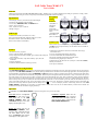
LAN Cable Tester With LCT
User's Guide
Welcome
Thank you for purchasing this LAN Cable Tester Series product. Whether you are a contractor installing LAN cabling as a profession or simply a small
office administrator caring for a LAN, we hope that you will find this product both useful and rewarding.
Specifications
• LCD Display: 2 lines by 12 characters with LED back light
• Connectors: RJ-45 (8P8C) jacks with shield
• Control keys: MODE/SEL, ESC, and ENTER buttons
• Power: 9V dry cell battery.
• Size: 15.0(H) x 6.5(W) x 3.5(D) cm
• Weight: 180g net
Cable Types
Unshielded Twisted Pair (UTP 100Ω, Cat 3,4 & 5)
Foil screened Twisted Pair (FTP 100Ω and 120Ω, Cat 3,4 & 5)
Shielded Twisted Pair (STP 150Ω IBM Type 1&6)
RG-58 Coaxial cable (LCT400 ONLY)
Recognized
Wiring
Schemes
10(100)Base-T
Token Ring
TP-PMD
AT&T 258A
EIA/TIA-568A/B
USOC
10(100)Base/HUB
BNC/10Base-2
plus 4 User Defined
Cable Locator
Cable location may be accomplished by using multiple RP-T terminators.
The RP-T locators incorporate factory set I.D. numbers and are available in
ID’s from 1 to 16.
Features
• Hand-held and easy to operate.
• Easy to read LCD display, with back light.
• Easy to diagnose RJ-45 cables (and BNC types with LCT400) with preset
wiring schemes.
• Easy to read cable status, verify cable continuity: open, short, and
mismatches.
• Scan pin assignment.
• Automatic cable identification. (Cable type search.)
• Standard pin configurations and four(4) user defined cable wirings
memorized in CPU.
• Can save user defined cable directly after testing.
• Tests for both shielded and unshielded cable types.
• Review the captured pin assignment and failure status.
• Maximum testing length is up to 3000 feet.
• Identify and trace the other end’s ID. (with up to 16 individual ID RP-T)
• Battery low indicator.
• Auto power-off function.
Automatic Power Saving Features
The LAN CABLE TESTER has built in power management features intended to extend battery life. By far, the LCD back light is the most power hungry
component in the LAN CABLE TESTER. Use of the LCD back light should therefore be limited to low ambient light applications. The back light may be
toggled ON/OFF by simultaneously pressing the MODE/SEL and ESC function keys. If there is no further menu selection or function testing within thirty
(30) seconds, the back light will be automatically extinguished. Additional power management functions include both a “sleep” mode and an auto “power
off” mode. If there is not any key activity for three (3) minutes, the unit will automatically enter “sleep” mode. All interface circuitry and the LCD display
will be powered down. In this mode the unit draws very little power. Pressing any key will cause the unit to “wake up” to a full functioning state. However,
if there is no key activity for ten (10) minutes, the unit will automatically “power off”. To recover from the “power off” mode, the unit must have its power
switch cycled OFF and then ON. In the “power off” mode the power usage is close to nil. This feature is especially useful if the unit is inadvertently left
powered on. The battery should be replaced when the battery low icon
( ) on the LCD display becomes visible during normal use of the LAN
CABLE TESTER . Additionally, if a low battery is swapped within 1 minute with a new one, the user defined memory contents will be retained. Just
remember to turn the unit OFF before swapping the battery.
Operation
← Connection: The LAN CABLE TESTER is capable of testing cables in any one of four modes.
Local Test mode is accomplished
by connecting both ends of the
cable under test to the LAN
CABLE TESTER OUT and
LOOPBACK IN ports. Local unit
displays an ID equal to zero.
Remote Test mode uses two (2)
LAN CABLE TESTER units,
with the cable connected between
one unit’s OUT and the other
unit’s LOOPBACK IN. Remote
unit displays an ID equal to zero.
Terminator Loopback mode uses the
supplied terminator ID block connected
at the remote end of the cable, while the
other end of the cable is connected to the
LAN CABLE TESTER OUT.
Operation (continued)
Turn power switch on: Following initial power on of the LAN CABLE TESTER, the unit will display the startup logo with back light for 3 seconds,
then will display the top menu for “cable test”.
LAN CABLE TESTER startup menu
∗
CTC
UNI ON
MO D E
LCT
. . v 1 . 0
c a b l e
i
S E L :
t e s t
Type
Results Displayed
Press “ENTER” to test the cable.
o
Battery
Low
Icon
LAN CABLE TESTER test menu
Pin Out
1 2 3 4 5 6 7 8 G
1 0 0 B AS E / HUB
UTP, FTP or COAX
3 6 1 4 5 2 7 8
UT P
Terminator
ID No.
i d : 1
Use MODE/SEL to toggle between cable pin out screen and result display, press ESC back to test menu.
Cable testing: During any mode of cable testing, the first screen display will show the top line out and bottom line in of connections 1 through 8 plus G
(shield) as they are scanned. Following this screen page will be the cable identification information. If at least one wire pair is not connected, the display
will read “NO CONNECT”. A shorted cable will read “SHORT”. A question mark in the pin out display indicates a short. An unknown is not in the
standard known pin outs or in the user defined memory.
User Defined cable: The User Define function allows you to describe your own custom cable pin out which will be entered into the cable identification
database and saved in the CPU memory. This custom pin out will remain available as long as a fresh battery is in the unit. Two methods are available for
defining a cable. The first method is manual entry, while the second uses an "UNKNOWN" cable as the pin out source. First the manual method. From
the very top of the LAN CABLE TESTER menu (just after power on is completed) select the USER DEF menu by pressing the MODE/SEL button (step
no. 1 to 2). The MODE/SEL button will now move the cursor to select one of four (4) user memory locations (step no. 3). Press ENTER to select the
memory location that the cursor is on. The define cable display will show (step no. 4).
LAN CABLE TESTER user defined menu
LAN CABLE TESTER test menu
MO D E
S EL:
c a b l e
*
t e s t
MODE/SEL
#
DEF .
d e f i n e d
o
*
MODE/SEL
to location 1~4 then ENTER
1 / 2 / 3 / 4
S EL:
u s e r
∗
ENTER
LAN CABLE TESTER Define cable display
LAN CABLE TESTER User Def display (4 locations)
US ER
MO D E
1 2 3 4 5 6 7 8 G
empty
i
Use the ENTER key to set digits 1 to 8, G or blank (not connected), then press MODE/SEL to move to the next space.
When completed, press ESC.(step no. 5 to 6)
LAN CABLE TESTER defined pin out
o
1 2 3 4 5 6 7 8 G
i
3 4 1 2 6 5 7 8
To save your definition,
U N K N O WN
UTP
∗
defined
pin out
∗
press ENTER. To exit without saving,
DEF .
i d : 1
∗
∗
S AVE
MODE/SEL
DE F .
LAN CABLE TESTER Save to User Defined
Confirmation display
ESC
S AVE
TO
US ER
DE F .
# 2
?
press ESC. The alternate method is to save the "Unknown" type.
T O
US E R
?
∗
ENTER
ESC out
US ER
#
DEF .
1 / 2 / 3 / 4
Select the location with MODE/SEL and then press ENTER to save. Press ESC anytime to exit.
Cable Fault Indication Examples:
MO D E
c a b l e
S EL:
t e s t
∗
ENTER
o
1 2 3 4 5 6 7 8 G
i
1 1 3 4 5 6 7 8
CABLE
S HORT
i d : 1
In the above example, Pin 1 and Pin 2 were found to be shorted.
MO D E
c a b l e
S EL:
t e s t
∗
o
ENTER
1 2 3 4 5 6 7 8 G
NO
CONNE CT
i
In the second example, if at least one pair of wires is not connected, the test result will show as "NO CONNECT".
41RP-170300-000