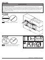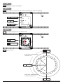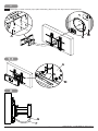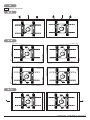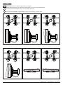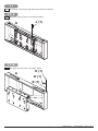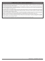
1
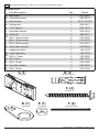
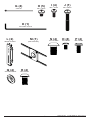
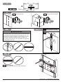
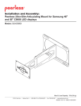
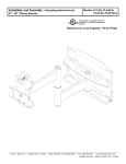
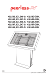
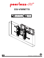
DS-VWM770
46" - 70"
(1168 - 1778 cm)
MAX
125 lb
(56 kg)
ENG
1
2013-08-27
#:125-9465-3 2013-10-11
ENG This page intentionally left blank.
2
2013-08-27
#:125-9465-3 2013-10-11
WARNING
ENG - This product is designed to be installed on wood stud, solid concrete or cinder block walls. Hardware is
included for wood stud, solid concrete and cinder block installation. Before installing make sure the supporting
surface will support the combined load of the equipment and hardware. Screws must be tightly secured. Do
not overtighten screws or damage can occur and product may fail. Never exceed the Maximum Load Capacity.
Always use an assistant or mechanical lifting equipment to safely lift and position equipment. This product is
intended for indoor use only. Use of this product outdoors could lead to product failure or personal injury. Be
careful not to pinch fingers when operating the mount. For support please call customer care at 1-800-865-2112.
ENG Symbols
x3
ENG Warning
ENG Screws must get at least three
full turns and fit snug.
ENG Do not overtighten screws.
#
ENG Tools Needed for Assembly.
ENG Skip to step.
ENG To properly tighten screws: Tighten until screw
head makes contact, then tighten another 1/2
turn. Do not overtighten screws.
1
2
3
5/32"
(4mm)
+1/2
4
5/16"
(8mm)
3/8"
(10mm)
3
2013-08-27
#:125-9465-3 2013-10-11
ENG Parts (Before beginning, make sure you have all parts shown below).
Parts List
Part Description
wall plate
Qty.
A
1
201-0387
B
concrete anchor
4
590-0320
C
wood screw
4
5S1-015-C03
D
locking tab
1
200-1871
E
.219" spacer
1
540-1032
F
polyester sleeve
2
600-1014
G
cable tie
4
560-9711
H
M5 x 10mm screw
5
520-1063
I
M4 x 12mm screw
4
510-1079
J
M5 x 40mm screw
1
510-1001
K
4mm allen wrench
1
560-9646
L
adapter bracket
2
145-1779
M
plate assembly
1
145-1784
N
M10 x 15mm
4
520-9262
O
M5 x 8mm
4
520-1167
P
M6 x 12mm
4
520-1050
Q
shoulder washer
4
590-2233
R
M8 x 15mm
4
520-1068
A (1)
Part #
B (4)
wall plate
concrete anchor
C (4)
wood screw
D (1)
locking tab
E (1)
F (2)
.219" spacer
polyester sleeve
4
2013-08-27
#:125-9465-3 2013-10-11
G (4)
H (5)
cable tie
M5 x 10mm
I (4)
M4 x 12mm
J (1)
M5 x 40mm
K (1)
4mm allen wrench
L (2)
Q (4)
shoulder washer
N (4)
M (1)
adapter bracket
M10 x 15mm
plate assembly
O (4)
M5 x 8mm
P (4)
M6 x 12mm
R (4)
M8 x 15mm
5
2013-08-27
#:125-9465-3 2013-10-11
1
A
ENG Remove
2
ENG Wood stud wall.
ENG Concrete/Cinder block.
2a
2a
2b
2a-1
WARNING
ENG Use stud finder to locate
and mark stud center lines.
ENG
ENG - When installing Peerless wall mounts on a
wood stud wall covered with gypsum board (drywall),
verify that the woods studs are a minimum of 2" x 4"
nominal size. When installing to more than one stud,
ensure the spacing between studs is at least 16"
but does not exceed 24". Do not install over gypsum
board thicker than 5/8".
2a-2
A
ENG Level wallplate.
Mark mounting holes on stud centerlines.
6
2013-08-27
#:125-9465-3 2013-10-11
2a-3
2.5"
(64mm)
5/32"
(4mm)
5/32"
(4mm)
ENG Drill mounting holes into supporting surface
(2.5" (64mm) minimum depth required).
ENG Mounting hole must center on stud.
2a-4
ENG Level wallplate. Install using wood screws provided.
A
C (4)
ENG Maximum 80 in. • lb (9 N.M.).
3
7
2013-08-27
#:125-9465-3 2013-10-11
2b
WARNING
ENG • When installing Peerless wall mounts on a concrete wall, the wall must be at least 8" thick with a minimum
compressive strength of 2000 psi.
• When installing Peerless wall mounts on a cinder block wall, the cinder blocks must meet ASTM C-90
specifications and have a minimum nominal width of 8". Do not drill into mortar joints! Be sure to mount in a solid
part of the block, generally 1" (25 mm) minimum from the side of the block. It is suggested that a standard electric
drill on slow setting is used to drill the hole instead of a hammer drill to avoid breaking out the back of the hole
when entering a void or cavity.
• Never attach expansion anchors to concrete or cinder block covered with plaster, drywall or other finishing
material.
2b-1
A
ENG Level wallplate. Mark mounting holes.
2b-2
2.5"
(64mm)
5/16"
(8mm)
5/16"
(8mm)
ENG Drill mounting holes into supporting surface
(2.5" (64mm) minimum depth required).
ENG Do not drill into mortar joints.
8
2013-08-27
#:125-9465-3 2013-10-11
2b-3
B
ENG Insert anchor flush to concrete.
B (4)
2b-4
1b-4
ENG Level wallplate. Install using concrete
anchors and wood screws provided.
A
ENG Maximum 80 in. • lb (9 N.M.).
C (4)
9
2013-08-27
#:125-9465-3 2013-10-11
3
A
10
2013-08-27
#:125-9465-3 2013-10-11
4
ENG Setting the angle of the display.
4-1
ENG The viewport is used to reveal notches indicating the view of the display.
M
ENG Rotating Plate
ENG Notch
ENG Viewport
4-2
ENG Line up the viewport with the desired view.
M
ENG Viewport
ENG Rotating Plate
ENG Rotation Guide
45
ENG Portrait
TOP OF TV
PORTRAIT
90°
EACH display
MARK
Each notch rotates
ROTATES TV
clockwise 15° CLOCKWISE
60°
75°
90°
-75°
-90°
45°
30°
15°
LANDSCAPE
ENG Landscape
0°
-15°
-30°
-45°
-60°
90°
ROTATION PLATE
EACH MARKdisplay
ROTATES TV
Each notch rotates
BOTTOM OF THE TV
COUNTER-CLOCKWISE
counter-clockwise 15°
ENG Portrait
11
DETAIL A
SCALE 2 : 1.5
2013-08-27
#:125-9465-3 2013-10-11
5
ENG Leaving ¼", thread two M10 x 15mm (N) screws through plate assembly (M) and rotating plate.
ENG Rotating Plate
M
N
6
ENG Slide plate assembly (M) into adapter bracket (L) slots.
M
L
12
2013-08-27
#:125-9465-3 2013-10-11
6-1
ENG Determine VESA mounting pattern.
300mm x 300mm
400mm x 400mm
400mm x 300mm
400mm x 200mm
500mm x 400mm
600mm x 400mm
13
2013-08-27
#:125-9465-3 2013-10-11
6-2
L
Q
P, R
6-3
ENG Secure plate assembly (M) to adapter bracket (L) with four M5 x 8mm screws (O).
L
M
O
ENG Do not use screws on inner adapter bracket
opening.
14
2013-08-27
#:125-9465-3 2013-10-11
7
ENG
Slide M10 x 15mm screws (N) of plate assembly (M) into top two key holes of wall plate (A).
N M
A
7-1
A
N
M
8
G
F
15
2013-08-27
#:125-9465-3 2013-10-11
9
ENG Display adjustment.
9-1
9-2
9-3
16
2013-08-27
#:125-9465-3 2013-10-11
10
ENG Use legend below to determine position of display.
NOTE: Each knob can be adjusted independently for fine tuning adjustments.
Turn knob CLOCKWISE to move corner toward the wall.
Turn knob COUNTER-CLOCKWISE to move corner away from the wall.
17
2013-08-27
#:125-9465-3 2013-10-11
11
ENG OPTIONAL: Alternative wall plate (A) lock-down positions.
11-1
ENG Wall plate (A) lock-down in retracted position.
A
J (1)
11-2
ENG Wall plate (A) lock-down one arm in place.
A
H (1)
D (1)
E (1)
18
2013-08-27
#:125-9465-3 2013-10-11
LIMITED FIVE-YEAR WARRANTY
Peerless Industries, Inc. (“Peerless”) warrants to original end-users of Peerless® products will be free from defects in material and
workmanship, under normal use, for a period of five years from the date of purchase by the original end-user (but in no case longer than
six years after the date of the product's manufacture). At its option, Peerless will repair or replace, or refund the purchase price of, any
product which fails to conform with this warranty.
In no event shall the duration of any implied warranty of merchantability or fitness for a particular purpose be longer than the
period of the applicable express warranty set forth above. Some states do not allow limitations on how long a implied warranty lasts,
so the above limitation may not apply to you.
This warranty does not cover damage caused by (a) service or repairs by the customer or a person who is not authorized for such service
or repairs by Peerless, (b) the failure to utilize proper packing when returning the product, (c) incorrect installation or the failure to follow
Peerless' instructions or warnings when installing, using or storing the product, or (d) misuse or accident, in transit or otherwise, including
in cases of third party actions and force majeure.
In no event shall Peerless be liable for incidental or consequential damages or damages arising from the theft of any product,
whether or not secured by a security device which may be included with the Peerless® product. Some states do not allow the
exclusion or limitation of incidental or consequential damages, so the above limitation or exclusion may not apply to you.
This warranty is in lieu of all other warranties, expressed or implied, and is the sole remedy with respect to product defects. No dealer,
distributor, installer or other person is authorized to modify or extend this Limited Warranty or impose any obligation on Peerless in
connection with the sale of any Peerless® product.
This warranty gives specific legal rights, and you may also have other rights which vary from state to state.
Patented. Utility Patent No. 8,517,322
19
2013-08-27
#:125-9465-3 2013-10-11
Peerless-AV
2300 White Oak Circle
Aurora, IL 60502
Email: [email protected]
Ph: (800) 865-2112
Fax: (800) 359-6500
www.peerless-av.com
© 2013, Peerless Industries, Inc.
20
2013-08-27
#:125-9465-3 2013-10-11