1
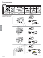
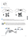
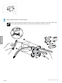
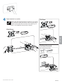
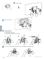
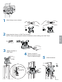
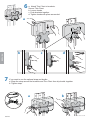
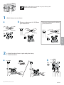
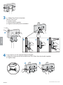
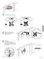
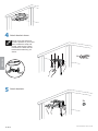
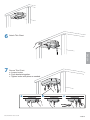
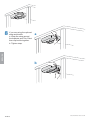
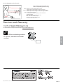
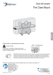
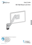
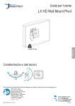
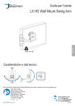
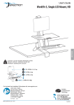
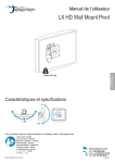
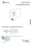
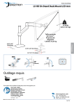
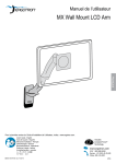
User's Guide
Thin Client Mount
ENGLISH
Features & Specifications
0.85" - 2.3" (22-58 mm)
< 6 lbs. (2.7 kg)
CAUTION: DO NOT EXCEED MAXIMUM LISTED
WEIGHT CAPACITY. SERIOUS INJURY OR
PROPERTY DAMAGE MAY OCCUR!
IMPORTANT! This product adds an additional 2 lbs. (1 kg) to your mounting solution. When mounting
between a monitor and VESA plate, the mounting solution's monitor weight capacity must be reduced
by 2 lbs. (1 kg) when using standard monitors and thin clients which when combined are less than
or equal to 2.5" (64 mm) thick. Additional reduction will be required if the combined monitors and thin
client are greater than 2.5" (64 mm) thick.
For the latest User Installation Guide please visit: www.ergotron.com
User's Guide - English
Guía del usuario - Español
Manuel de l’utilisateur - Français
Gebruikersgids - Deutsch
Benutzerhandbuch - Nederlands
Guida per l’utente - Italiano
Användarhandbok - svenska
ユーザーガイド : 日本語
用户指南 : 汉语
888-97-341-G-01 rev. C • 02/14
1 of 15
Components
A
1
B
1x
1x
C
1x
E
2x 4x 2x
F
G
1x
1x
H
4x
M4
4x
2
2x
#8 x 3/4"
3
D
1x
M4
1x
Follow desired mounting
application instructions.
M3 x 10mm
1x
M3.5 x 8mm
4x
M4 x 16mm
1x
4x
M4 x 12mm
M4 x 10mm
M4 x 10mm
3
Tools Needed
ENGLISH
7mm
7
Tools Needed
9
Tools Needed
11
Tools Needed
Ø 1/8" (3 mm)
888-97-341-G-01 rev. C • 02/14
2 of 15
1
Attach bump-ons as shown.
4x
ENGLISH
2
2x
Install Portrait/Landscape rotation stop screw.
Insert the provided washer and one of the three provided rotation stop screws : M3x10 mm,
M3.5x8mm, or M4x10mm depending on the diameter of the hole in your VESA plate.
WARNING! Thin Client may fall out of brackets. Install the Portrait/Landscape
rotation stop screw to keep monitor from rotating through the portrait/landscape
rotation. Failure to follow these instructions may result in the Thin Client falling out
of the brackets and could result in equipment damage and/or personal injury.
1x
1x
M3 x 10mm
M4
1x
M3.5 x 8mm
1x
M4 x 10mm
888-97-341-G-01 rev. C • 02/14
3 of 15
3
Attach bracket shown to VESA mount.
NOTE: Using the strap and buckle is optional. If you would like to include the strap and buckle, make
sure the strap is between the VESA mount and the bracket when attaching, as shown.
ENGLISH
4x
M4 x 12mm
4x
M4
7mm
888-97-341-G-01 rev. C • 02/14
4 of 15
4
Attach bracket to monitor.
75x75mm
NOTE: Using the strap and buckle is optional. If you would
like to include the strap and buckle, make sure the strap is
between the bracket and the monitor when attaching, as
shown. This installation step requires 2 people.
4x
M4 x 10mm
100x100mm
4x
M4 x 10mm
ENGLISH
75x75mm Recessed
Kit Ordered Separately.
4x
M4 x 25mm
888-97-341-G-01 rev. C • 02/14
5 of 15
5
Attach brackets.
2x
ENGLISH
6
7
Attach Thin Client.
Secure Thin Client.
a. Loosen knobs.
b. Push brackets together.
c. Tighten knobs with pliers as needed.
a
8
b
c
If you are using the strap and buckle, clip buckle together and tighten strap.
888-97-341-G-01 rev. C • 02/14
6 of 15
1
Attach bump-ons as shown.
2x
4x
2
Attach bracket shown to Wall Track bracket.
NOTE: Leave enough space between brackets to allow sliding onto Wall Track.
ENGLISH
2x
M4 x 16mm
3
Attach brackets to
Wall Track.
4
Tighten screws to
secure brackets to Wall
Track at desired height.
5
Attach brackets.
2x
888-97-341-G-01 rev. C • 02/14
7 of 15
6
a. Attach Thin Client to brackets.
Secure Thin Client.
b. Loosen knobs.
c. Push brackets together.
d. Tighten knobs with pliers as needed.
a
ENGLISH
b
7
c
d
If you want to use the optional strap and buckle:
a. Wrap the strap around the brackets and Thin Client then clip buckle together.
b. Tighten strap.
a
b
888-97-341-G-01 rev. C • 02/14
8 of 15
NOTE: If Thin Client is mounted on a pole, this may limit
the amount of arm rotation.
1
Attach bump-ons as shown.
a
placement for 35-38mm
b Bump-on
pole attachment.
Bump-on placement for 40mm
pole attachment.
35-38mm
40mm
4x
2x
2x
ENGLISH
2
a
a. Attach bracket shown to pole and pole clamp.
b. Attach brackets.
35-38mm
40mm
b
2x
2x
M4 x 16mm
888-97-341-G-01 rev. C • 02/14
9 of 15
3
a. Attach Thin Client to brackets.
Secure Thin Client.
b. Loosen knobs.
c. Push brackets together.
d. Tighten knobs with pliers as needed.
ENGLISH
a
b
4
c
d
If you want to use the optional strap and buckle:
a. Wrap the strap around the brackets and Thin Client then clip buckle together.
b. Tighten strap.
a
b
888-97-341-G-01 rev. C • 02/14
10 of 15
1
Attach bump-ons as shown.
4x
2x
ENGLISH
2
3
Mark mounting holes in
desired location using
bracket shown.
Drill holes.
TIP: To ensure proper
depth, place a piece of tape
on the drill bit 0.75" (19 mm)
from the tip.
Ø 1/8" (3 mm)
0.75"
(19 mm)
888-97-341-G-01 rev. C • 02/14
11 of 15
4
Attach bracket shown.
NOTE: Using the strap and
buckle is optional. If you would
like to include the strap and
buckle, make sure the strap
is between the desk and the
bracket when attaching, as
shown.
4x
ENGLISH
#8 x 3/4"
5
Attach brackets.
2x
888-97-341-G-01 rev. C • 02/14
12 of 15
6
Attach Thin Client.
ENGLISH
7
Secure Thin Client.
a. Loosen knobs.
b. Push brackets together.
c. Tighten knobs with pliers as needed.
a
b
c
888-97-341-G-01 rev. C • 02/14
13 of 15
If you are using the optional
strap and buckle:
a. Wrap the strap around
the brackets and Thin Client
then clip buckle together.
b. Tighten strap.
a
ENGLISH
8
b
888-97-341-G-01 rev. C • 02/14
14 of 15
Set Your Workstation to Work For YOU!
Learn more about ergonomic computer use at:
www.computingcomfort.org
Height Position top of screen slightly below eye level.
Position keyboard at about elbow height with wrists flat.
Distance Position screen an arm's length from face—at least 20” (508mm).
Position keyboard close enough to create a 90˚ angle in elbow.
Angle Tilt screen to eliminate glare.
Tilt the keyboard back 10° so that your wrists remain flat.
To Reduce Fatigue
Breathe - Breathe deeply through your nose.
Blink - Blink often to avoid dry eyes.
Break • 2 to 3 minutes every 20 minutes
• 15 to 20 minutes every 2 hours.
Service and Warranty
For local customer care phone numbers visit: http://contact.ergotron.com
ENGLISH
NOTE: When contacting customer service, reference the serial
number.
888-97-341-G-01 rev. C • 02/14
15 of 15