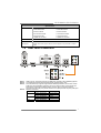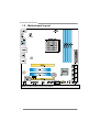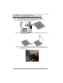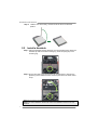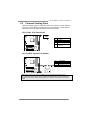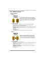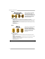
1
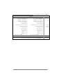
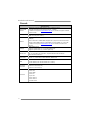
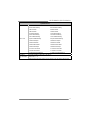
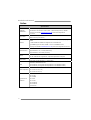
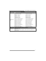
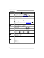
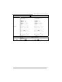
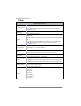
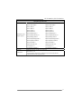
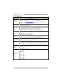
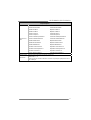
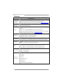
Hi-Fi A88S3+/Hi-Fi A78S3+ Setup Manual FCC Information and Copyright This equipment has been tested and found to comply with the limits of a Class B digital device, pursuant to Part 15 of the FCC Rules. These limits are designed to provide reasonable protection against harmful interference in a residential installation. This equipment generates, uses, and can radiate radio frequency energy and, if not installed and used in accordance with the instructions, may cause harmful interference to radio communications. There is no guarantee that interference will not occur in a particular installation. The vendor makes no representations or warranties with respect to the contents here and specially disclaims any implied warranties of merchantability or fitness for any purpose. Further the vendor reserves the right to revise this publication and to make changes to the contents here without obligation to notify any party beforehand. Duplication of this publication, in part or in whole, is not allowed without first obtaining the vendor’s approval in writing. The content of this user’s manual is subject to be changed without notice and we will not be responsible for any mistakes found in this user’s manual. All the brand and product names are trademarks of their respective companies. Dichiarazione di conformità sintetica Ai sensi dell’art. 2 comma 3 del D.M. 275 del 30/10/2002 Si dichiara che questo prodotto è conforme alle normative vigenti e soddisfa i requisiti essenziali richiesti dalle direttive 2004/108/CE, 2006/95/CE e 1999/05/CE quando ad esso applicabili Short Declaration of conformity We declare this product is complying with the laws in force and meeting all the essential requirements as specified by the directives 2004/108/CE, 2006/95/CE and 1999/05/CE whenever these laws may be applied Table of Contents Chapter 1: Introduction.......................................... 1 1.1 1.2 1.3 1.4 1.5 Before You Start ................................................................................1 Package Checklist ............................................................................1 Motherboard Specifications .............................................................2 Rear Panel Connectors....................................................................3 Motherboard Layout..........................................................................4 Chapter 2: Hardware Installation ........................... 5 2.1 2.2 2.3 2.4 2.5 2.6 2.7 Install Central Processing Unit (CPU)............................................5 Install a Heatsink ...............................................................................6 Connect Cooling Fans......................................................................7 Install System Memory .....................................................................8 Expansion Slots...............................................................................10 Jumper Setting ................................................................................11 Headers & Connectors ...................................................................12 Chapter 3: UEFI BIOS & Software ........................ 18 3.1 3.2 3.3 UEFI BIOS Setup ............................................................................18 BIOS Update....................................................................................18 Software............................................................................................22 Chapter 4: Useful Help ......................................... 26 4.1 4.2 4.3 4.4 4.5 Driver Installation.............................................................................26 AMI BIOS Beep Code.....................................................................27 Troubleshooting...............................................................................27 RAID Functions ...............................................................................29 AMD Dual Graphics Technology ...................................................31 Appendix: Specifications in Other Languages....... 34 Arabic.....................................................................................................................34 French ...................................................................................................................36 German .................................................................................................................38 Italian .....................................................................................................................40 Japanese...............................................................................................................42 Polish .....................................................................................................................44 Portuguese ...........................................................................................................46 Russian .................................................................................................................48 Spanish..................................................................................................................50 Hi-Fi A88S3+/Hi-Fi A78S3+ CHAPTER 1: INTRODUCTION 1.1 Before You Start Thank you for choosing our product. Before you start installing the motherboard, please make sure you follow the instructions below: Prepare a dry and stable working environment with sufficient lighting. Always disconnect the computer from power outlet before operation. Before you take the motherboard out from anti-static bag, ground yourself properly by touching any safely grounded appliance, or use grounded wrist strap to remove the static charge. Avoid touching the components on motherboard or the rear side of the board unless necessary. Hold the board on the edge, do not try to bend or flex the board. Do not leave any unfastened small parts inside the case after installation. Loose parts will cause short circuits which may damage the equipment. Keep the computer from dangerous area, such as heat source, humid air and water. The operating temperatures of the computer should be 0 to 45 degrees Celsius. To avoid injury, be careful of: Sharp pins on headers and connectors Rough edges and sharp corners on the chassis Damage to wires that could cause a short circuit 1.2 Package Checklist ; ; ; ; Serial ATA Cable x2 Rear I/O Panel for ATX Case x1 User’s Manual x1 Fully Setup Driver DVD x1 Note: The package contents may be different due to the sales region or models in which it was sold. For more information about the standard package in your region, please contact your dealer or sales representative. 1 Motherboard Manual 1.3 Motherboard Specifications Specifications Socket FM2+/FM2 for AMD A-series processor CPU Support Maximum CPU TDP (Thermal Design Power): 100Watt * Please refer to www.biostar.com.tw for CPU support list. Chipset AMD A88X FCH (Hi-Fi A88S3+) AMD A78 FCH (Hi-Fi A78S3+) Supports Dual Channel DDR3 800/ 1066/ 1333/ 1600/ 1866/ 2133/ 2400(OC)/ 2600(OC) Memory 4 x DDR3 DIMM Memory Slot, Max. Supports up to 64 GB Memory Each DIMM supports non-ECC 512MB/ 1/ 2/ 4/ 8/ 16 GB DDR3 module * Please refer to www.biostar.com.tw for Memory support list. AMD A88X/A78 FCH Storage Supports RAID 0,1,10, 5 & AHCI (AMD A88X FCH) Supports RAID 0,1,10 & AHCI (AMD A78 FCH), LAN Audio Codec Realtek RTL 8111G 10/ 100/ 1000 Mb/s auto negotiation, Half / Full duplex capability ALC892 7.1 Channels, High Definition Audio, Biostar Hi-Fi AMD A88X/A78 FCH: USB 8x USB 2.0 port (4 on rear I/Os and 4 via internal headers) 4x USB 3.0 port (2 on rear I/Os and 2 via internal headers) 2x PCI Slot Expansion Slots 1x PCIe 3.0 x16 Slot (x16) (Only FM2+ processors can support PCIe 3.0.) 1x PCIe 2.0 x16 Slot (x4) 1x PS/2 Mouse & Keyboard 1x VGA Port 1x HDMI Port Rear I/Os 1x DVI Port 1x LAN port 4x USB 2.0 Port 2x USB 3.0 Port 6x Audio Jack Internal I/Os 2 Hi-Fi A88S3+: Hi-Fi A78S3+: 8x SATA 6.0Gb/s Connector 6x SATA 6.0Gb/s Connector 2x USB 2.0 Header 2x USB 2.0 Header 1x USB 3.0 Header 1x USB 3.0 Header 1x 4-Pin Power Connector 1x 4-Pin Power Connector 1x 24-Pin Power Connector 1x 24-Pin Power Connector 1x CPU Fan Connector 1x CPU Fan Connector 2x System Fan Connector 2x System Fan Connector 1x Front Panel Header 1x Front Panel Header Hi-Fi A88S3+/Hi-Fi A78S3+ Specifications Form Factor 1x Front Audio Header 1x Front Audio Header 1x Clear CMOS Header 1x Clear CMOS Header 1x Printer Port Header 1x Printer Port Header 1x Consumer IR Header 1x Consumer IR Header 1x Serial Port Header 1x Serial Port Header 1x S/PDIF out Connector 1x S/PDIF out Connector microATX Form Factor, 243.84 mm x 237.50 mm Windows XP / 7 / 8 OS Support Biostar reserves the right to add or remove support for any OS with or without notice. 1.4 Note 1: Note 2: Note 3: Note 4: Rear Panel Connectors HDMI / DVI-D / VGA Output require an AMD family processor with intedrated graphics. The mainboard supports three onboard display outputs at same time. Since the audio chip supports High Definition Audio Specification, the function of each audio jack can be defined by software. The input / output function of each audio jack listed above represents the default setting. However, when connecting external microphone to the audio port, please use the Line In (Blue) and Mic In (Pink) audio jack. Maximum resolution: Outputs HDMI DVI-D VGA Maximum resolution 1920 x 1080 @60Hz 1920 x 1200 @60Hz 1920 x 1200 @60Hz 2560 x 1600 @60Hz 1920 x 1600 @60Hz Bit Depth 24, 30, 36 bpp 24 bpp 30 bpp 24 bpp -- 3 Motherboard Manual 1.5 Motherboard Layout Note1: ■ represents the 1st pin. Note2: The SATA4 connector is only for Hi-Fi A88S3+. 4 Hi-Fi A88S3+/Hi-Fi A78S3+ CHAPTER 2: HARDWARE INSTALLATION 2.1 Install Central Processing Unit (CPU) Step 1: Locate the CPU socket on the motherboard Step 2: Pull the socket locking out from the socket and then raise the lever up to a 90-degree angel. Step 3: Look for the white triangle on socket, and the gold triangle on CPU should point towards this white triangle. The CPU will fit only in the correct orientation. 5 Motherboard Manual Step 4: Hold the CPU down firmly, and then close the lever to locked the position 2.2 Install a Heatsink Step 1: Place the heatsink and fan assembly onto the retention frame. Match the heatsink clip with the socket mounting-lug. Hook the spring clip to the mounting-lug. Step 2: On the other side, push the retention clip straight down to lock into the plastic lug on the retention frame, and then press down the locker until it stops. Note1: Do not forget to connect the CPU fan connector. Note2: For proper installation, please kindly refer to the installation manual of your CPU heatsink. 6 Hi-Fi A88S3+/Hi-Fi A78S3+ 2.3 Connect Cooling Fans These fan headers support cooling-fans built in the computer. The fan cable and connector may be different according to the fan manufacturer. Connect the fan cable to the connector while matching the black wire to pin#1. CPU_FAN1: CPU Fan Header Pin 1 2 3 Assignment Ground +12V FAN RPM rate sense 4 Smart Fan Control (By Fan) Pin 1 2 3 Assignment Ground +12V SYS_FAN1/2: System Fan Header FAN RPM rate sense Note: CPU_FAN1, SYS_FAN1/2 support 4-pin and 3-pin head connectors. When connecting with wires onto connectors, please note that the red wire is the positive and should be connected to pin#2, and the black wire is Ground and should be connected to GND. 7 Motherboard Manual 2.4 Install System Memory A. DDR3 Modules Step 1: Unlock a DIMM slot by pressing the retaining clips outward. Align a DIMM on the slot such that the notch on the DIMM matches the break on the slot. Step 2: Insert the DIMM vertically and firmly into the slot until the retaining clips snap back in place and the DIMM is properly seated. Note: If the DIMM does not go in smoothly, do not force it. Pull it all the way out and try again. 8 Hi-Fi A88S3+/Hi-Fi A78S3+ B. Memory Capacity DIMM Socket Location DDR3 Module DDR3_A1 512MB/1GB/2GB/4GB/8GB/16GB DDR3_A2 512MB/1GB/2GB/4GB/8GB/16GB DDR3_B1 512MB/1GB/2GB/4GB/8GB/16GB DDR3_B2 512MB/1GB/2GB/4GB/8GB/16GB Total Memory Size Max is 64GB. C. Dual Channel Memory Installation Please refer to the following requirements to activate Dual Channel function: Install memory module of the same density in pairs, shown in the table. Dual Channel Status DDR3_A1 DDR3_A2 DDR3_B1 DDR3_B2 Enabled O X O X Enabled X O X O Enabled O O O O (O means memory installed, X means memory not installed.) Note: The DRAM bus width of the memory module must be the same (x8 or x16) 9 Motherboard Manual 2.5 Expansion Slots PEX16_1: PCI-Express Gen3 x16 Slot - PCI-Express 3.0 compliant. Maximum theoretical realized bandwidth of 16GB/s simultaneously per direction, for an aggregate of 32GB/s totally. Only FM2+ processors can support PCIe 3.0. PEX16_2: PCI-Express Gen2 x4 Slot - PCI-Express 2.0 compliant. Maximum theoretical realized bandwidth of 2GB/s simultaneously per direction, for an aggregate of 4GB/s totally. PCI1/2: Peripheral Component Interconnect Slot This motherboard is equipped with 1 standard PCI slot. PCI stands for Peripheral Component Interconnect, and it is a bus standard for expansion cards. Install an Expansion Card You can install your expansion card by following steps: 1. Read the related expansion card's instruction document before install the expansion card into the computer. 2. Remove your computer's chassis cover, screws and slot bracket from the computer. 3. Place a card in the expansion slot and press down on the card until it is completely seated in the slot. 4. Secure the card’s metal bracket to the chassis back panel with a screw. 5. Replace your computer's chassis cover. 6. Power on the computer, if necessary, change BIOS settings for the expansion card. 7. Install related driver for the expansion card. 10 Hi-Fi A88S3+/Hi-Fi A78S3+ 2.6 Jumper Setting The illustration shows how to set up jumpers. When the jumper cap is placed on pins, the jumper is “close”, if not, that means the jumper is “open”. Pin opened Pin closed Pin1-2 closed JCMOS1: Clear CMOS Header Placing the jumper on pin2-3, it allows user to restore the BIOS safe setting and the CMOS data. Please carefully follow the procedures to avoid damaging the motherboard. 1 3 Pin 1-2 Close: Normal Operation (default). 1 3 Pin 2-3 Close: Clear CMOS data. ※ Clear CMOS Procedures: 1. 2. 3. 4. 5. 6. Remove AC power line. Set the jumper to “Pin 2-3 close”. Wait for five seconds. Set the jumper to “Pin 1-2 close”. Power on the AC. Load Optimal Defaults and save settings in CMOS. 11 Motherboard Manual 2.7 Headers & Connectors ATXPWR1: ATX Power Source Connector For better compatibility, we recommend to use a standard ATX 24-pin power supply for this connector. Make sure to find the correct orientation before plugging the connector. Pin 13 14 15 16 17 18 19 20 21 22 23 24 Assignment +3.3V -12V Ground PS_ON Ground Ground Ground NC +5V +5V +5V Ground Pin 1 2 3 4 5 6 7 8 9 10 11 12 Assignment +3.3V +3.3V Ground +5V Ground +5V Ground PW_OK Standby Voltage+5V +12V +12V +3.3V ATXPWR2: ATX Power Source Connector This connector will provide +12V to CPU power circuit. Pin 1 2 3 4 Assignment +12V +12V Ground Ground Note1: Before you power on the system, please make sure that both ATXPWR1 and ATXPWR2 connectors have been plugged-in. Note2: Insufficient power supplied to the system may result in instability or the peripherals not functioning properly. Use of a PSU with a higher power output is recommended when configuring a system with more power-consuming devices. 12 Hi-Fi A88S3+/Hi-Fi A78S3+ PANEL1: Front Panel Header This 16-pin connector includes Power-on, Reset, HDD LED, Power LED, and speaker connection. It allows user to connect the PC case’s front panel switch functions. Pin 1 2 3 4 5 6 7 8 Assignment +5V N/A N/A Speaker HDD LED (+) HDD LED (-) Ground Reset control Function Speaker Connector Hard drive LED Reset button Pin 9 10 11 12 13 14 15 16 Assignment N/A N/A N/A Power LED (+) Power LED (+) Power LED (-) Power button Ground Function N/A N/A Power LED Power-on button SATA1~SATA4: Serial ATA Connectors These connectors connect to SATA hard disk drives via SATA cables. Hi-Fi A88S3+ & Hi-Fi A78S3+ satisfy the SATA 3.0 spec and with transfer rate of 6.0Gb/s. The SATA4 (SATA4-U/SATA4-L) connector is only for Hi-Fi A88S3+. Pin 1 2 3 4 5 6 7 Assignment Ground TX+ TXGround RXRX+ Ground 13 Motherboard Manual JFRONT_USB3_1: Header for USB 3.0 Ports at Front Panel This header allows user to connect additional USB cable on the PC front panel, and also can be connected with a wide range of simultaneously accessible external Plug and Play peripherals. Pin 1 2 3 4 5 6 7 8 9 10 Assignment VBUS0 SSRX1SSRX1+ Ground SSTX1SSTX1+ Ground D1D1+ ID Pin 11 12 13 14 15 16 17 18 19 20 Assignment D2+ D2Ground SSTX2+ SSTX2Ground SSRX2+ SSRX2VBUS1 Key F_USB1/F_USB2: Headers for USB 2.0 Ports at Front Panel This header allows user to connect additional USB cable on the PC front panel, and also can be connected with a wide range of simultaneously accessible external Plug and Play peripherals. Pin 1 2 3 4 5 6 7 8 9 10 14 Assignment +5V (fused) +5V (fused) USBUSBUSB+ USB+ Ground Ground NC Key Hi-Fi A88S3+/Hi-Fi A78S3+ F_AUDIO1: Front Panel Audio Header This header allows user to connect the front audio output cable with the PC front panel. This header supports HD and AC’97 audio front panel connector. Pin 1 2 3 4 5 6 7 8 9 10 HD Audio Assignment Mic Left in Ground Mic Right in GPIO Right line in Jack Sense Front Sense Key Left line in Jack Sense Pin 1 2 3 4 5 6 7 8 9 10 AC’97 Assignment Mic In Ground Mic Power Audio Power RT Line Out RT Line Out Reserved Key LFT Line Out LFT Line Out Note1: It is recommended that you connect a high-definition front panel audio module to this connector to avail of the motherboard's high definition audio capability. Note2: Please try to disable the "Front Panel Jack Detection" if you want to use an AC'97 front audio output cable. The function can be found via O.S. Audio Utility. J_COM1: Serial Port Connector The motherboard has a Serial Port Connector for connecting RS-232 Port. Pin Assignment 1 2 3 4 5 6 7 8 9 10 Carrier detect Received data Transmitted data Data terminal Signal ground Data set ready Request to send Clear to send Ring indicator NC 15 Motherboard Manual J_PRINT1: Printer Port Connector This header allows you to connector printer on the PC. Pin 1 2 3 4 5 6 7 8 9 10 11 12 13 Assignment -Strobe -ALF Data 0 -Error Data 1 -Init Data 2 -Scltin Data 3 Ground Data 4 Ground Data 5 Pin 14 15 16 17 18 19 20 21 22 23 24 25 26 Assignment Ground Data 6 Ground Data 7 Ground -ACK Ground Busy Ground PE Ground SCLT Key CIR1: Consumer IR Header This header is for infrared remote control and communication. Pin 1 2 3 4 5 6 16 Assignment IrDA serial input Ground Ground Key IrDA serial output IR Power Hi-Fi A88S3+/Hi-Fi A78S3+ JSPDIFOUT1: Digital Audio-out Connector The connector is for connecting the PCI bracket SPDIF output. Pin Assignment 1 2 3 +5V SPDIF_OUT Ground 17 Motherboard Manual CHAPTER 3: UEFI BIOS & SOFTWARE 3.1 3.2 UEFI BIOS Setup For better system performance, the UEFI BIOS firmware is being continuously updated. The UEFI BIOS information described below in this manual is for your reference only and the actual UEFI BIOS information and settings on board may be different from this manual For further information of setting up the UEFI BIOS, please refer to the UEFI BIOS Manual in the Setup DVD. BIOS Update There are three ways to update the BIOS: BIOS Update Utility, BIOS Online Update Utility and BIOS Flasher. 1. BIOS Update Utility 1. Installing BIOS Update Utility from the DVD Driver. 2. Download the proper BIOS from www.biostar.com.tw . 3. Open BIOS Update Utility and click the Update BIOS button on the main screen. 4. A warning message will show up to request your agreement to start the BIOS update. Click OK to start the update procedure. 5. Choose the location for your BIOS file in the system. Please select the proper BIOS file, and then click on Open. It will take several minutes, please be patient. 18 Hi-Fi A88S3+/Hi-Fi A78S3+ 6. After the BIOS Update process is finished, click on OK to reboot the system. 7. While the system boots up and the full screen logo shows up, please press the <Delete> key to enter BIOS setup. After entering the BIOS setup, please go to the Save & Exit, using the Restore Defaults function to load Optimized Defaults, and select Save Changes and Reset to restart the computer. Then, the BIOS Update is completed. Backup BIOS Click the Backup BIOS button on the main screen for the backup of BIOS, and select a proper location for your backup BIOS file in the system, and click Save. 2. Online Update Utility 1. Installing BIOS Update Utility from the DVD Driver. 2. Please make sure the system is connected to the internet before using this function. 3. Open BIOS Update Utility and click the Online Update button on the main screen. 4. An open dialog will show up to request your agreement to start the BIOS update. Click Yes to start the online update procedure. 19 Motherboard Manual 5. If there is a new BIOS version, the utility will ask you to download it. Click Yes to proceed. 6. After the download is completed, you will be asked to program (update) the BIOS or not. Click Yes to proceed. 7. After the updating process is finished, you will be asked you to reboot the system. Click OK to reboot. 8. While the system boots up and the full screen logo shows up, press <Delete> key to enter BIOS setup. After entering the BIOS setup, please go to the Save & Exit, using the Restore Defaults function to load Optimized Defaults, and select Save Changes and Reset to restart the computer. Then, the BIOS Update is completed. 3. BIOSTAR BIOS Flasher BIOSTAR BIOS Flasher is a BIOS flashing utility providing you an easy and simple way to update your BIOS via USB pen drive. Note1: This utility only allows storage device with FAT32/16 format and single partition. Note2: Shutting down or resetting the system while updating the BIOS will lead to system boot failure. The BIOSTAR BIOS Flasher is built in the BIOS ROM. To enter the utility, press <F12> during the Power-On Self Tests (POST) procedure while booting up. Updating BIOS with BIOSTAR BIOS Flasher 1. Go to the website to download the latest BIOS file for the motherboard. 2. Then, copy and save the BIOS file into a USB flash (pen) drive. 3. Insert the USB pen drive that contains the BIOS file to the USB port. 4. Power on or reset the computer and then press <F12> during the POST process. 20 Hi-Fi A88S3+/Hi-Fi A78S3+ 5. After entering the POST screen, the BIOS-FLASHER utility pops out. Choose [fs0] to search for the BIOS file. 6. Select the proper BIOS file, and a message asking if you are sure to flash the BIOS file. Click Yes to start updating BIOS. 7. A dialog pops out after BIOS flash is completed, asking you to restart the system. Press the [Y] key to restart system. 8. While the system boots up and the full screen logo shows up, press <Delete> key to enter BIOS setup. After entering the BIOS setup, please go to the Save & Exit, using the Restore Defaults function to load Optimized Defaults, and select Save Changes and Reset to restart the computer. Then, the BIOS Update is completed. 21 Motherboard Manual 3.3 Software Installing Software 1. Insert the Setup DVD to the optical drive. The driver installation program would appear if the Autorun function has been enabled. 2. Select Software Installation, and then click on the respective software title. 3. Follow the on-screen instructions to complete the installation. Note1: All the information and content about following software are subject to be changed without notice. For better performance, the software is being continuously updated. Note2: The information and pictures described below are for your reference only. The actual information and settings on board may be slightly different from this manual. Launching Software After the installation process is completed, you will see the software icon showing on the desktop. Double-click the icon to launch it. eHot-Line eHot-Line is a convenient utility that helps you to contact with our Tech-Support system. This utility will collect the system information which is useful for analyzing the problem you may have encountered, and then send these information to our tech-support department to help you fix the problem. Note: Before you use this utility, please set Outlook Express as your default e-mail client application program. represents important information that you must provide. Without this information, you may not be able to send out the mail. * This block will show the information which would be collected in the mail. condition *Describe of your system. your area or *Select the area close to you. Provide the e-mail address that you would like to send the copy to. the name of *Provide the memory module manufacturer. Provide the name of the power supply manufacturer and the model no. Send the mail out. Exit this dialog. Save these information to a .txt file 22 Hi-Fi A88S3+/Hi-Fi A78S3+ After filling up this information, click “Send” to send the mail out. A warning dialog would appear asking for your confirmation; click “Send” to confirm or “Do Not Send” to cancel. If you want to save this information to a .txt file, click “Save As…” and then you will see a saving dialog appears asking you to enter file name. Enter the file name and then click “Save”. Your system information will be saved to a .txt file. Open the saved .txt file, you will see your system information including motherboard/BIOS/CPU/video/ device/OS information. This information is also concluded in the sent mail. Note1: We will not share customer’s data with any other third parties, so please feel free to provide your system information while using eHot-Line service. Note2: If you are not using Outlook Express as your default e-mail client application, you may need to save the system information to a .txt file and send the file to our tech support with other e-mail application. Go to the following web http://www.biostar.com.tw/app/en/about/contact.php for getting our contact information. 23 Motherboard Manual BIOScreen Utility This utility allows you to personalize your boot logo easily. You can choose BMP as your boot logo so as to customize your computer. Please follow the following instructions to update boot logo: z Load Image:Choose the picture as the boot logo. z Transform:Transform the picture for BIOS and preview the result. z Update Bios:Write the picture to BIOS Memory to complete the update. 24 Hi-Fi A88S3+/Hi-Fi A78S3+ Smart EAR Smart EAR is a windows-based audio utility which allows you to easily adjust system volume. With its user-friendly GUI, you can also adjust impedance setting (Low/High Gain) to optimize your headphone performance. z High/Low Gain Switch: Keep the gain switch to low for low impedance headphone and set to high for high impedance headphone. z Mute Button: To disable system sound z Volume Control Knob: The volume can be finely adjusted by turning the knob either clockwise or anti-clockwise to increase or decrease system volume accordingly. z Information Button: Get information of the application z Minimize Button: Minimize the application window to the taskbar z Exit Button: Exit the application Note: 1. Smart EAR is only supported by Windows 7/8 and BIOSTAR Hi-Fi series motherboards. 2. High/Low Gain Switch is only for “Front Panel Audio Header”, please make sure you are connecting your headphone to the front panel I/O. 25 Motherboard Manual CHAPTER 4: USEFUL HELP 4.1 Driver Installation After you installed your operating system, please insert the Fully Setup Driver DVD into your optical drive and install the driver for better system performance. You will see the following window after you insert the DVD The setup guide will auto detect your motherboard and operating system. Note: If this window didn’t show up after you insert the Driver DVD, please use file browser to locate and execute the file SETUP.EXE under your optical drive. A. Driver Installation To install the driver, please click on the Driver icon. The setup guide will list the compatible driver for your motherboard and operating system. Click on each device driver to launch the installation program. B. Software Installation To install the software, please click on the Software icon. The setup guide will list the software available for your system, click on each software title to launch the installation program. C. Manual Aside from the paperback manual, we also provide manual in the Driver DVD. Click on the Manual icon to browse for available manual. Note: You will need Acrobat Reader to open the manual file. Please download the latest version of Acrobat Reader software from http://get.adobe.com/reader/ 26 Hi-Fi A88S3+/Hi-Fi A78S3+ 4.2 AMI BIOS Beep Code Boot Block Beep Codes Number of Beeps Continuing Description Memory sizing error or Memory module not found POST BIOS Beep Codes Number of Beeps 1 8 4.3 Description Success booting. Display memory error (system video adapter) Troubleshooting Probable 1. 2. Solution There is no power in the system. 1. Power LED does not shine; the fan of the power supply does not work 2. Indicator light on keyboard does 3. not shine. Make sure power cable is securely plugged in. Replace cable. Contact technical support. System is inoperative. Keyboard lights Using even pressure on both ends of the are on, power indicator lights are lit, DIMM, press down firmly until the module and hard drives are running. snaps into place. System does not boot from a hard disk 1. drive, but can be booted from optical drive. 2. Check cable running from disk to disk controller board. Make sure both ends are securely plugged in; check the drive type in the standard CMOS setup. Backing up the hard drive is extremely important. All hard disks are capable of breaking down at any time. System only boots from an optical drive. Hard disks can be read, applications can be used, but system fails to boot from a hard disk. 1. 2. Screen message shows “Invalid Configuration” or “CMOS Failure.” Review system’s equipment. Make sure correct information is in setup. System cannot boot after user installs 1. a second hard drive. 2. Back up data and applications files. Reformat the hard drive. Re-install applications and data using backup disks. Set master/slave jumpers correctly. Run SETUP program and select correct drive types. Call the drive manufacturers for compatibility with other drives. 27 Motherboard Manual CPU Overheated If the system shutdown automatically after power on system for seconds, that means the CPU protection function has been activated. When the CPU is over heated, the motherboard will shutdown automatically to avoid a damage of the CPU, and the system may not power on again. In this case, please double check: 1. The CPU cooler surface is placed evenly with the CPU surface. 2. CPU fan is rotated normally. 3. CPU fan speed is fulfilling with the CPU speed. After confirmed, please follow steps below to relief the CPU protection function. 1. Remove the power cord from power supply for seconds. 2. Wait for seconds. 3. Plug in the power cord and boot up the system. Or you can: 1. Clear the CMOS data. (See “Close CMOS Header: JCMOS1” section) 2. Wait for seconds. 3. Power on the system again. 28 Hi-Fi A88S3+/Hi-Fi A78S3+ 4.4 RAID Functions RAID Definitions RAID 0: In a RAID 0 system data are split up in blocks that get written across all the drives in the array. By using multiple disks (at least 2) at the same time, this offers superior I/O performance. This performance can be enhanced further by using multiple controllers, ideally one controller per disk. Features and Benefits Drives: Minimum 2, and maximum is up to 6 or 8. Depending on the platform. Uses: Intended for non-critical data requiring high data throughput, or any environment that does not require fault tolerance. Benefits: provides increased data throughput, especially for large files. No capacity loss penalty for parity. Drawbacks: Does not deliver any fault tolerance. If any drive in the array fails, all data is lost. Fault Tolerance: No. Total Capacity: (Minimal. HDD Capacity) x (Connected HDDs Amount) RAID 1: Data are stored twice by writing them to both the data disk(or set of data disks) and a mirror disk (or set of disks). If a disk fails, the controller uses either the data drive or the mirror drive for data recovery and continues operation. You need at least 2 disks for a RAID 1 array. Features and Benefits Drives: Minimum 2, and maximum is 2. Uses: RAID 1 is ideal for small databases or any other application that requires fault tolerance and minimal capacity. Benefits: Provides 100% data redundancy. Should one drive fail, the controller switches to the other drive. Drawbacks: Requires 2 drives for the storage space of one drive. Performance is impaired during drive rebuilds. Fault Tolerance: Yes. 29 Motherboard Manual RAID 10: RAID 10 combines the advantages (and disadvantages) of RAID 0 and RAID 1 in one single system. It provides security by mirroring all data on a secondary set of disks (disk 3 and 4 in the drawing below) while using striping across each set of disks to speed up data transfers. Features and Benefits Drives: Minimum 4, and maximum is 6 or 8, depending on the platform. Benefits: Optimizes for both fault tolerance and performance, allowing for automatic redundancy. May be simultaneously used with other RAID levels in an array, and allows for spare disks. Drawbacks: Requires twice the available disk space for data redundancy, the same as RAID level 1. Fault Tolerance: Yes. RAID 5: A RAID 5 array can withstand a single disk failure without losing data or access to data. Although RAID 5 can be achieved in software, a hardware controller is recommended. Often extra cache memory is used on these controllers to improve the write performance. Features and Benefits Drives: Minimum 3. Uses: RAID 5 is recommended for transaction processing and general purpose service. Benefits: An ideal combination of good performance, good fault tolerance, and high capacity and storage efficiency. Drawbacks: Individual block data transfer rate same as a single disk. Write performance can be CPU intensive. Fault Tolerance: Yes. Note: The RAID 5 function is only supported by A88X chipset. 30 Hi-Fi A88S3+/Hi-Fi A78S3+ 4.5 AMD Dual Graphics Technology AMD Dual Graphics Technology Introduction When user adds a PCIE display adapter, it can be integrated with IGD to show better performance. To make the two video devices work simultaneously and normally, please refer to the following setting. MD Dual Graphics Requirement Operating System: Windows 7 / Windows 8 Supported Dual Graphics Combinations: Richland APUs AMD Radeon™ Graphics Card A10-Series HD 8670D A8-Series HD8570D A6-Series HD 8470D “Oland” XT, HD 8870 ● ● ●(Note2) “Oland” Pro, HD 8850 ● ● ● “Turks” XT, HD 6670 ● ● ● “Turks” Pro, HD 6570 ● ● ● “Caicos” Pro, HD 6450 ● ● ● AMD Radeon™ Graphics Card A10-Series HD 7660D A8-Series HD7560D A6-Series HD 7540D “Turks” XT, HD 6670 ● ● -- “Turks” Pro, HD 6570 ● ● ● -- ● Trinity APUs “Caicos” Pro, HD 6450 -● Recommended graphics cards for AMD dual-graphics Note 1: A4-Series CPUs do not support Dual Graphics. Note 2: Only available for DDR3 graphics memory Note 3: The information described above in this manual is for your reference only and the actual information and settings on board may be different from this manual. For further AMD Dual Graphics information, please visit the following website: http://www.amd.com 31 Motherboard Manual AMD Dual Graphics Setup Step 1: Insert Dual Graphics-Ready graphics card into PEX16_1 slot. Step 2: Set the BIOS setting as follows: [Chipset]→[North Bridge]→[GFX Configuration] →[Surround View]→[Enabled] Step 3: Install Driver DVD Chipset Driver, and reboot the system. Activate AMD VISION Engine Control Center to make sure CrossFire has been enabled. 32 Hi-Fi A88S3+/Hi-Fi A78S3+ This Page Intentionally Left Blank 33 Motherboard Manual APPENDIX: Specifications in Other Languages Arabic اﻟﻤﻮاﺻﻔﺎت ﻗﺎﻋﺪة وﺣﺪة اﻟﻤﺄﺧﺬ FM2+/FM2ﻟﻤﻌﺎﻟﺞ اﻳﻪ إم دى AMDﺗﺴﻠﺴﻞ A اﻟﻤﻌﺎﻟﺠﺔ اﻟﺤﺪ اﻷﻗﺼﻰ ﻟﻠﻄﺎﻗﺔ اﻟﺤﺮارﻳﺔ ﻓﻲ ﺗﺼﻤﻴﻢ اﻟﻤﻌﺎﻟﺞ ) 100 :( thermal design power – TDPواط. اﻟﻤﺮآﺰﻳﺔ * ﻳﺮﺟﻰ اﻟﺮﺟﻮع إﻟﻰ اﻟﻤﻮﻗﻊ www.biostar.com.twﻟﻘﺎﺋﻤﺔ دﻋﻢ اﻟﻤﻌﺎﻟﺞ .CPU ﻣﺠﻤﻮﻋﺔ )AMD A88X FCH (Hi-Fi A88S3+ اﻟﺸﺮاﺋﺢ )AMD A78 FCH (Hi-Fi A78S3+ ﺗﺪﻋﻢ ﻗﻨﺎة ﻣﺰدوﺟﺔ دي .دي .ار2600(OC)/2400(OC)/ 2133 /1866 / 1600 / 1333 / 1066 / 800 DDR3 . اﻟﺬاآﺮة x4دي .دي .ار DDR3 .ﻓﺘﺤﺎت اﻟﺬاآﺮة اﻟﻤﺰدوﺟﺔ ،DIMMﺗﺘﺤﻤﻞ آﺤﺪ أﻗﺼﻰ 64ﺟﻴﺠﺎﺑﺎﻳﺖ ذاآﺮة آﻞ ﻓﺘﺤﺔ ﻣﺰدوﺟﺔ DIMMﺗﺘﺤﻤﻞ دون 512 ECCﻣﻴﺠﺎ ﺑﺎﻳﺖ 16/8/4/2/1/ﺟﻴﺠﺎﺑﺎﻳﺖ دي .دي .ار DDR3 * ﻳﺮﺟﻰ اﻟﺮﺟﻮع إﻟﻰ اﻟﻤﻮﻗﻊ www.biostar.com.twﻟﻘﺎﺋﻤﺔ دﻋﻢ اﻟﺬاآﺮة. اﻳﻪ إم دى FCH A88X/A78 AMD اﻟﺘﺨﺰﻳﻦ ﺗﺘﺤﻤﻞ راﻳﺪ (FCH A88X)AHCI / 10 / 1 / 0 / 5 RAID ﺗﺘﺤﻤﻞ راﻳﺪ (FCH A78)AHCI / 10 / 1 / 0 RAID ﺷﺒﻜﺔ ﻣﺤﻠﻴﺔ رﻳﻴﺎﻟﺘﻴﻚ رت ل REALTEK RTL 8111G LAN 1000 / 100 / 10ﻣﻴﺠﺎﺑﺎﻳﺖ /اﻟﺜﺎﻧﻴﺔ ،ﺗﺤﺪﻳﺪ ﺗﻠﻘﺎﺋﻲ ،اﻟﻨﺼﻒ /اﻟﻘﺪرة اﻟﻘﺼﻮى اﻟﻤﺰدوﺟﺔ اﻟﺘﺮﻣﻴﺰ اﻟﺼﻮﺗﻲ ﻧﺎﻗﻞ ﻣﺘﺴﻠﺴﻞ ﻋﺎم USB ALC892 7.1ﻗﻨﻮات ﻋﺎﻟﻴﺔ اﻟﺪﻗﺔBiostar Hi-Fi, ﻳﻪ إم دى FCH AMD A88X/A78 ﻣﻨﺎﻓﺬ 8 xﻧﺎﻗﻞ ﻣﺘﺴﻠﺴﻞ ﻋﺎم 4 ) 2.0 USBﻓﻲ اﻟﻤﺪاﺧﻞ واﻟﻤﺨﺎرج اﻟﺨﻠﻔﻴﺔ و 4ﻣﻦ ﺧﻼل اﻟﻤﻮزع اﻟﺪاﺧﻠﻲ ( ﻣﻨﺎﻓﺬ 4 xﻧﺎﻗﻞ ﻣﺘﺴﻠﺴﻞ ﻋﺎم 2 ) 3.0 USBﻓﻲ اﻟﻤﺪاﺧﻞ واﻟﻤﺨﺎرج اﻟﺨﻠﻔﻴﺔ و 2ﻣﻦ ﺧﻼل اﻟﻤﻮزع اﻟﺪاﺧﻠﻲ ( x 2ﻓﺘﺤﺔ ﻣﻨﻔﺬ اﻟﻤﻠﺤﻘﺎت اﻹﺿﺎﻓﻴﺔ PCI ﻓﺘﺤﺎت اﻟﺘﻮﺳﻊ x 1ﻓﺘﺤﺔ ﻣﻨﻔﺬ اﻟﻤﻠﺤﻘﺎت اﻹﺿﺎﻓﻴﺔ (x16) PCIe 3.0 x16 x 1ﻓﺘﺤﺔ ﻣﻨﻔﺬ اﻟﻤﻠﺤﻘﺎت اﻹﺿﺎﻓﻴﺔ (x4) PCIe 2.0 x16 PS/2 x 1اﻟﻔﺎرة& ﻟﻮﺣﺔ اﻟﻤﻔﺎﺗﻴﺢ ﻟﻠﻜﻤﺒﻴﻮت ﻓﺘﺤﺔ ﺗﻮﺻﻴﻞ ﻋﺪد x 1ﻣﻨﻈﻮﻣﺔ اﻟﻌﺮض اﻟﻤﺮﺋﻲ VGA اﻟﻤﺪاﺧﻞ واﻟﻤﺨﺎرج اﻟﺨﻠﻔﻴﺔ ﻓﺘﺤﺔ ﺗﻮﺻﻴﻞ ﻋﺪد x 1واﺟﻬﺔ ﻣﺮﺋﻴﺔ رﻗﻤﻴﺔ HDMI ﻓﺘﺤﺔ ﺗﻮﺻﻴﻞ ﻋﺪد x 1واﺟﻬﺔ ﻣﺮﺋﻴﺔ رﻗﻤﻴﺔ DVI ﻓﺘﺤﺔ ﻟﺘﻮﺻﻴﻞ ﻋﺪد x 1اﻟﺸﺒﻜﺔ اﻟﻤﺤﻠﻴﺔ LAN ﻓﺘﺤﺔ ﺗﻮﺻﻴﻞ ﻋﺪد x 4ﻧﺎﻗﻞ ﻣﺘﺴﻠﺴﻞ ﻋﺎم 2.0 USB ﻓﺘﺤﺔ ﺗﻮﺻﻴﻞ ﻋﺪد x 2ﻧﺎﻗﻞ ﻣﺘﺴﻠﺴﻞ ﻋﺎم 3.0 USB ﻓﺘﺤﺔ ﺗﻮﺻﻴﻞ ﻋﺪد x 6ﺟﺎك ﻟﻠﺼﻮت 34 Hi-Fi A88S3+/Hi-Fi A78S3+ اﻟﻤﻮاﺻﻔﺎت +Hi-Fi A88S3 +Hi-Fi A78S3 وﺻﻠﺔ 6 x SATA 8ﺟﻴﺠﺎﺑﺎﻳﺖ /اﻟﺜﺎﻧﻴﺔ وﺻﻠﺔ 6 x SATA 6ﺟﻴﺠﺎﺑﺎﻳﺖ /اﻟﺜﺎﻧﻴﺔ ﻣﻮزع x2ﻧﺎﻗﻞ ﻣﺘﺴﻠﺴﻞ ﻋﺎم 2.0 USB ﻣﻮزع x2ﻧﺎﻗﻞ ﻣﺘﺴﻠﺴﻞ ﻋﺎم 2.0 USB ﻣﻮزع x1ﻧﺎﻗﻞ ﻣﺘﺴﻠﺴﻞ ﻋﺎم 3.0 USB ﻣﻮزع x1ﻧﺎﻗﻞ ﻣﺘﺴﻠﺴﻞ ﻋﺎم 3.0 USB ﻣﻮﺻﻠﺔ ﻟﻠﻄﺎﻗﺔ 4 x 1دﺑﺎﺑﻴﺲ ﻣﻮﺻﻠﺔ ﻟﻠﻄﺎﻗﺔ 4 x 1دﺑﺎﺑﻴﺲ وﺻﻠﺔ ﻟﻠﻄﺎﻗﺔ 24 x1دﺑﻮس وﺻﻠﺔ ﻟﻠﻄﺎﻗﺔ 24 x1دﺑﻮس اﻟﻤﺪاﺧﻞ وﺻﻠﺔ x 1ﻣﺮوﺣﺔ ﺗﺒﺮﻳﺪ وﺣﺪة اﻟﻤﻌﺎﻟﺠﺔ اﻟﻤﺮآﺰﻳﺔ وﺻﻠﺔ x 1ﻣﺮوﺣﺔ ﺗﺒﺮﻳﺪ وﺣﺪة اﻟﻤﻌﺎﻟﺠﺔ اﻟﻤﺮآﺰﻳﺔ واﻟﻤﺨﺎرج وﺻﻠﺔ x2ﻣﺮاوح ﺗﺒﺮﻳﺪ اﻟﻤﻨﻈﻮﻣﺔ وﺻﻠﺔ x2ﻣﺮاوح ﺗﺒﺮﻳﺪ اﻟﻤﻨﻈﻮﻣﺔ اﻟﺪاﺧﻠﻴﺔ ﻣﻮزع x 1اﻟﻠﻮﺣﺔ اﻷﻣﺎﻣﻴﺔ ﻣﻮزع x 1اﻟﻠﻮﺣﺔ اﻷﻣﺎﻣﻴﺔ ﻣﻮزع x1اﻟﺼﻮت اﻷﻣﺎﻣﻲ ﻣﻮزع x1اﻟﺼﻮت اﻷﻣﺎﻣﻲ ﻣﻮزع x1ﺳﻴﻤﻮس ﻣﺒﺎﺷﺮ ﻣﻮزع x1ﺳﻴﻤﻮس ﻣﺒﺎﺷﺮ ﻣﻮزع x1ﻓﺘﺤﺔ ﻟﻠﻄﺎﺑﻌﺔ ﻣﻮزع x1ﻓﺘﺤﺔ ﻟﻠﻄﺎﺑﻌﺔ ﻣﻮزع x 1ﻣﺴﺘﻬﻠﻚ IR ﻣﻮزع x 1ﻣﺴﺘﻬﻠﻚ IR ﻣﻮزع x 1ﻓﺘﺤﺔ ﺗﺴﻠﺴﻠﻴﺔ ﻣﻮزع x 1ﻓﺘﺤﺔ ﺗﺴﻠﺴﻠﻴﺔ وﺻﻠﺔ x 1ﺧﺎرﺟﻴﺔ S/PDIFﺳﻮﻧﻲ ﻓﻴﻠﻴﺒﺲ اﻟﻮاﺟﻬﺔ اﻟﺮﻗﻤﻴﺔ وﺻﻠﺔ x 1ﺧﺎرﺟﻴﺔ S/PDIFﺳﻮﻧﻲ ﻓﻴﻠﻴﺒﺲ اﻟﻮاﺟﻬﺔ اﻟﺮﻗﻤﻴﺔ ﻋﺎﻣﻞ اﻟﺸﻜﻞ ﻋﺎﻣﻞ ﺷﻜﻞ ﻣﺪد اﻟﺘﻜﻨﻮﻟﻮﺟﻴﺎ اﻟﻤﺘﻘﺪﻣﺔ 243.84 ، microATXﻣﻢ 237.50 xﻣﻢ أﻧﻈﻤﺔ اﻟﺘﺸﻐﻴﻞ وﻳﻨﺪوز إآﺲ ﺑﻲ / windows xpوﻳﻨﺪوز / 7وﻳﻨﺪوز 8 اﻟﻤﺪﻋﻮﻣﺔ ﺑﻴﻮﺳﺘﺎر BIOSTARﺗﺤﺘﻔﻆ ﺑﺤﻖ إﺿﺎﻓﺔ أو أزﻟﺔ اﻟﺪﻋﻢ ﻷي ﻧﻈﺎم ﺗﺸﻐﻴﻞ ﻣﻊ أو ﺑﺪون أﻧﻈﺎر. 35 Motherboard Manual French Spécifications Interface de connexion FM2+/FM2 pour série A AMD processeur Support Unité Enveloppe thermique Unité Centrale maximum : 100Watt Centrale * Veuillez vous reporter à www.biostar.com.tw pour la liste des supports modèles d'Unité Centrale. Jeu de puces AMD A88X FCH (Hi-Fi A88S3+) AMD A78 FCH (Hi-Fi A78S3+) Supporte mémoire DDR3 double canal 800/ 1066/ 1333/ 1600/ 1866/ 2133/ 2400(OC)/ 2600(OC) Mémoire Banc de mémoire 4 x DDR3 DIMM, Supporte max. jusqu’à une mémoire de 64 GB Chaque module DIMM supporte module DDR3 non-ECC 512MB/ 1/ 2/ 4/ 8/ 16 GB * Veuillez vous reporter à www.biostar.com.tw pour la liste des soutien de la mémoire. AMD A88X/A78 FCH Stockage Supporte système RAID 0,1,10, 5 & AHCI (A88X FCH) Supporte système RAID 0,1,10 & AHCI (A78 FCH) Realtek RTL 8111G Réseau local 10/ 100/ 1000 Mb/s auto négociation, capacité bidirectionnelle à l'alternat / bidirectionnelle simultanée Codec audio ALC892 Canaux 7.1, écoute audio de haute définition, Biostar Hi-Fi AMD A88X/A78 FCH USB Port 8x USB 2.0 (4 sur les I/O arrières et 4 en interne) Port 4x USB 3.0 (2 sur les I/O arrières et 2 en interne) Connecteur d’extension 2x Fente PCI 1x PCIe 3.0 x16 Fente (x16) 1x PCIe 2.0 x16 Fente (x4) 1x PS/2 Clavier & Souris 1x Port VGA 1x Port HDMI I/O arrirèes 1x Port DVI 1x port LAN 4x Port USB 2.0 2x Port USB 3.0 6x entrées audio 36 Hi-Fi A88S3+/Hi-Fi A78S3+ Spécifications I/O en interne Facteur d'encombrement Hi-Fi A88S3+: Hi-Fi A78S3+: 8x Connecteur SATA 6.0Gb/s 6x Connecteur SATA 6.0Gb/s 2x embases USB 2.0 2x embases USB 2.0 1x embases USB 3.0 1x embases USB 3.0 1x 4-Broche de carte 1x 4-Broche de carte 1x 24-Broche de carte 1x 24-Broche de carte 1x Connecteur ventilateur unité centrale 1x Connecteur ventilateur unité centrale 2x Connecteur ventilateur système 2x Connecteur ventilateur système 1x Fiche panneau avant 1x Fiche panneau avant 1x Fiche audio avant 1x Fiche audio avant 1x Fiche mémoire CMOS vide 1x Fiche mémoire CMOS vide 1x Embase port imprimante 1x Embase port imprimante 1x Fiche Registre d’état Consommateur 1x Fiche Registre d’état Consommateur 1x Embase port série 1x Embase port série 1x Connecteur sortie S/PDIF 1x Connecteur sortie S/PDIF Facteur d'encombrement microATX, 243.84 mm x 237.50 mm Windows XP / 7 / 8 Support SE Biostar se réserve le droit d’ajouter ou d'enlever le support pour toute SE avec ou sans préavis. 37 Motherboard Manual German Spezifikationen Anschluss-FM2+/FM2 für AMD A-Serie Prozessor CPU-Unterstütz ung Chipset Maximale CPU TDP (Thermal Design Power): 100 Watt * Bitte konsultieren Sie www.biostar.com.tw für CPU-Unterstützungsliste AMD A88X FCH (Hi-Fi A88S3+) AMD A78 FCH (Hi-Fi A78S3+) Unterstützt zweikanaliges DDR3 800/ 1066/ 1333/ 1600/ 1866/ 2133/ 2400(OC)/ 2600(OC) Festplattenspeic her 4 x DDR3 DIMM-SpeicherSlot, Max. Uterstützung bis zu 64 GB-Speicher Jedes DIMM unterstützt nicht-ECC 512MB/ 1/ 2/ 4/ 8/ 16 GB DDR3-Module * Bitte konsultieren Sie www.biostar.com.tw für für Speicherunterstützung Liste. AMD A88X/A78 FCH Arbeitsspeicher Unterstützt RAID 0,1,10, 5 & AHCI (A88X FCH) Unterstützt RAID 0,1,10 & AHCI (A78 FCH) LAN Audio-Codec Realtek RTL 8111G 10/ 100/ 1000 Mb Auto-Negotiation, Halb- / Voll-Duplex-fähig ALC892 7.1 Kanäle, HD-Audio, Biostar Hi-Fi AMD A88X/A78 FCH: USB 8x USB 2.0-Port (4 hintere I/Os und 4 via interne Header) 4x USB 3.0-Port (2 hintere I/Os und 2 via interne Header) 2x PCI-Slot Erweiterungsan schlüsse 1x PCIe 3.0 x16-Slot (x16) 1x PCIe 2.0 x16-Slot (x4) 1x PS/2-Maus & Keyboard 1x VGA-Port 1x HDMI -Port Hintere I/Os 1x DVI-Port 1x LAN-Port 4x USB 2.0-Port 2x USB 3.0-Port 6x Audio Jack 38 Hi-Fi A88S3+/Hi-Fi A78S3+ Spezifikationen Interne I/Os Hi-Fi A88S3+: Hi-Fi A78S3+: 8x SATA 6.0Gb/s-Verbinung 6x SATA 6.0Gb/s-Verbinung 2x USB 2.0-Header 2x USB 2.0-Header 1x USB 3.0-Header 1x USB 3.0-Header 1x 4-Pin-Stromverbindung 1x 4-Pin-Stromverbindung 1x 24-Pin-Stromverbindung 1x 24-Pin-Stromverbindung 1x CPU-Ventilatorverbindung 1x CPU-Ventilatorverbindung 2x System-Ventilatorverbindung 2x System-Ventilatorverbindung 1x Header für Frontpanel 1x Header für Frontpanel 1x Header für Frontaudio 1x Header für Frontaudio 1x Header für klares CMOS 1x Header für klares CMOS 1x Header für Druckerport 1x Header für Druckerport 1x Consumer IR-Header 1x Consumer IR-Header 1x Serieller Port-Header 1x Serieller Port-Header 1x S/PDI-Auswurfsverbindung 1x S/PDI-Auswurfsverbindung Formfaktor microATX Formfaktor, 243.84 mm x 237.50 mm OS-Unterstützu Windows XP / 7 / 8 ng Biostar reserves the right to add or remove support for any OS with or without notice. 39 Motherboard Manual Italian Specificazioni Slot FM2+/FM2 per processore AMD serie-A Supporto processore Alimentazione di Proiezione Termico (TDP – Thermal Design Power): 100Watt * Si prega di consultare www.biostar.com.tw per la lista di supporto del processore. Tipo scheda AMD A88X FCH (Hi-Fi A88S3+) AMD A78 FCH (Hi-Fi A78S3+) Supporta DDR3 800/ 1066/ 1333/ 1600/ 1866/ 2133/ 2400(OC)/ 2600(OC) Doppio Canale Memoria 4 x DDR3 DIMM Slot di Memoria Supporta fino a 64 GB Memoria Ogni DIMM supporta non-ECC 512MB/ 1/ 2/ 4/ 8/ 16 GB DDR3 moduli * Si prega di consultare www.biostar.com.tw per la lista di supporto del memoria. AMD A88X/A78 FCH Memorizzazione Supporta RAID 0,1,10, 5 & AHCI (A88X FCH) Supporta RAID 0,1,10 & AHCI (A78 FCH) Catena Codec Audio Realtek RTL 8111G 10/ 100/ 1000 Mb auto negoziazione, capacita di duplex Meta / Completo ALC892 Canali Audio di Alta Definizione 7.1, Biostar Hi-Fi Piattaforma AMD A88X/A78 FCH: USB Slot 8x USB 2.0 (4 nei ingressi/ uscite posteriore e 4 da distributori interni) Slot 4x USB 3.0 (2 nei ingressi/ uscite posteriore e 2 da distributori interni) Slot 2x PCI Slot di espansione Slot 1x PCIe 3.0 x16 (x16) Slot 1x PCIe 2.0 x16 (x4) Tastiera & Mouse 1x PS/2 Slot 1x VGA Slot 1x HDMI Ingressi/ Uscite Slot 1x DVI Posteriore Slot 1x LAN Slot 4x USB 2.0 Slot 2x USB 3.0 Jack audio 6x 40 Hi-Fi A88S3+/Hi-Fi A78S3+ Specificazioni Ingressi/ Uscite Interni Fattore di Forma Hi-Fi A88S3+: Hi-Fi A78S3+: Connettore 8x SATA 6.0Gb/s Connettore 6x SATA 6.0Gb/s Distributore 2x USB 2.0 Distributore 2x USB 2.0 Distributore 1x USB 3.0 Distributore 1x USB 3.0 Connettore con 4 pin x1 Connettore con 4 pin x1 Connettore con 24 pin x1 Connettore con 24 pin x1 Connettore Ventilatore processore x1 Connettore Ventilatore processore x1 Connettore Ventilatore Sistema x2 Connettore Ventilatore Sistema x2 Distributore Pannello Frontale x1 Distributore Pannello Frontale x1 Distributore Audio Frontale x1 Distributore Audio Frontale x1 Distributore CMOS Diretto x1 Distributore CMOS Diretto x1 Distributore Slot Stampante x1 Distributore Slot Stampante x1 Distributore Consumabile IR x1 Distributore Consumabile IR x1 Distributore Slot Serie x1 Distributore Slot Serie x1 Connettore esterno S/PDIF x1 Connettore esterno S/PDIF x1 Fattore di Forma microATX, 243.84 mm x 237.50 mm Windows XP / 7 / 8 Supporto SO Biostar si riserva il diritto di aggiungere o ritirare il supporto per qualsiasi SO con o senza preavviso. 41 Motherboard Manual Japanese 仕様 AMD A-シリーズ プロセッサの Socket FM2+/FM2 CPU サポート 最大 CPU TDP (Thermal Design Power 最大放熱量):100 W *CPU サポート リストについては、www.biostar.com.twを参照してください。 チップセット AMD A88X FCH (Hi-Fi A88S3+) AMD A78 FCH (Hi-Fi A78S3+) デュアルチャンネル DDR3 800/ 1066/ 1333/ 1600/ 1866/ 2133/ 2400(OC)/ 2600(OC) をサポート 4 x DDR3 DIMM メモリ スロット、 最大 64 GB メモリまでサポート メモリ 各 DIMM は、 非-ECC 512MB/ 1/ 2/ 4/ 8/ 16 GB DDR3 モジュールをサポートしてい ます *サポートされているメモリのリストについては、www.biostar.com.twを参照してく ださい。 AMD A88X/A78 FCH 保存スペース RAID 0,1,10, 5 & AHCI のサポート (A88X FCH) RAID 0,1,10 & AHCI のサポート (A78 FCH) LAN Realtek RTL 8111G 10/ 100/ 1000 Mb/s オートネゴーシエーション、半/全 二重通信 オーディオ コーデ ALC892 ック 7.1 チャンネル, ハイ デフィニション オーディオ, Biostar Hi-Fi AMD A88X/A78 FCH: USB 8x USB 2.0 ポート (後部 I/O に4つ 及び 内蔵ヘッダー経由に4つ) 4x USB 3.0 ポート (後部 I/O に2つ 及び 内蔵ヘッダー経由に2つ) 2x PCI スロット 拡張スロット 1x PCIe 3.0 x16 スロット(x16) 1x PCIe 2.0 x16 スロット(x4) 1x PS/2 キーボード & マウス 1x VGA ポート 1x HDMI ポート 後部 I/O 1x DVI ポート 1x LAN ポート 4x USB 2.0 ポート 2x USB 3.0 ポート 6x オーディオ ジャック 42 Hi-Fi A88S3+/Hi-Fi A78S3+ 仕様 内蔵 I/O フォーム ファクタ サポート OS Hi-Fi A88S3+: Hi-Fi A78S3+: 8x SATA 6.0Gb/s コネクタ 6x SATA 6.0Gb/s コネクタ 2x USB 2.0 ヘッダー 2x USB 2.0 ヘッダー 1x USB 3.0 ヘッダー 1x USB 3.0 ヘッダー 1x 4-Pin パワー コネクタ 1x 4-Pin パワー コネクタ 1x 24-Pin パワー コネクタ 1x 24-Pin パワー コネクタ 1x CPU ファン コネクタ 1x CPU ファン コネクタ 2x システム ファン コネクタ 2x システム ファン コネクタ 1x フロント パネル ヘッダー 1x フロント パネル ヘッダー 1x フロント オーディオ ヘッダー 1x フロント オーディオ ヘッダー 1x クリア CMOS ヘッダー 1x クリア CMOS ヘッダー 1x プリンター ポート ヘッダー 1x プリンター ポート ヘッダー 1x コンシューマー IR ヘッダー 1x コンシューマー IR ヘッダー 1x シリアル ポート ヘッダー 1x シリアル ポート ヘッダー 1x S/PDIF アウト コネクタ 1x S/PDIF アウト コネクタ microATX フォーム ファクタ、243.84 mm x 237.50 mm Windows XP / 7 / 8 Biostar には、通知なしでサポート OS を変更する権限があります。 43 Motherboard Manual Polish Specyfikacje techniczne Gniazdo procesora (Socket) FM2+/FM2 dla procesorów AMD seria-A Obsługa procesora Moc Wydzielanego Ciepła (TDP - Thermal Design Power): 100Watt * Proszę sprawdzić listę obsługiwanych procesorów na stronie internetowej www.biostar.com.tw Rodzaj płyty AMD A88X FCH (Hi-Fi A88S3+) AMD A78 FCH (Hi-Fi A78S3+) Obsługa pamięci DDR3 800/ 1066/ 1333/ 1600/ 1866/ 2133/ 2400(OC)/ 2600(OC) Dwukanałowa 4 x DDR3 DIMM Pamięć Gniazda procesora (Slot), Maksymalna wielkość pamięci 64 Pamięć GB Każdy DIMM obsługuje jeden moduł non-ECC 512MB/ 1/ 2/ 4/ 8/ 16 GB DDR3 * Proszę sprawdzić listę obsługiwanych pamięć na stronie internetowej www.biostar.com.tw AMD A88X/A78 FCH Przechowywanie Obsługa RAID 0,1,10, 5 & AHCI (A88X FCH) Obsługa RAID 0,1,10 & AHCI (A78 FCH) LAN Codec Audio Układ RTL 8111G 10/ 100/ 1000 Mb auto negocjacja, pojemność dupleks Połowe / Pełny ALC892 Kanały Audio wysokiej Definicji 7.1, Biostar Hi-Fi Płyta AMD A88X/A78 FCH: USB 8 x złącza USB 2.0 (4 przez tylne porty wejścia/ wyjścia oraz 4 przez wewnętrzne porty) 4 x złącza USB 3.0 (2 przez tylne porty wejścia/ wyjścia oraz 2 przez wewnętrzne porty) złącza 2x PCI (Slot) Złącza rozszerzeń złącza 1x PCIe 3.0 x16 (Slot) (x16) złącza 1x PCIe 2.0 x16 (Slot) (x4) Klawiatura & Myszka 1x PS/2 Port 1x VGA Port 1x HDMI Tylne porty wejścia/ Port 1x DVI wyjścia Port 1x LAN Porty 4x USB 2.0 Porty 2x USB 3.0 Porty audio 6x 44 Hi-Fi A88S3+/Hi-Fi A78S3+ Specyfikacje techniczne Wewnętrzne porty wejścia/ wyjścia Obudowa Hi-Fi A88S3+: Hi-Fi A78S3+: Złącza 8x SATA 6.0Gb/s Złącza 6x SATA 6.0Gb/s Złącza 2x USB 2.0 Złącza 2x USB 2.0 Złącza 1x USB 3.0 Złącza 1x USB 3.0 Złącza 4 pionowe x 1 Złącza 4 pionowe x 1 Złącza 24 pionowe x 1 Złącza 24 pionowe x 1 Złącze wentylatora CPU x 1 Złącze wentylatora CPU x 1 Złącze wentylatora obudowy x 2 Złącze wentylatora obudowy x 2 Złącze przedniego panelu x1 Złącze przedniego panelu x1 Złącze audio przedniego panelu x1 Złącze audio przedniego panelu x1 Złącze bezpośrednie CMOS x1 Złącze bezpośrednie CMOS x1 Złącze port drukarki x1 Złącze port drukarki x1 Złącze konsument IR x1 Złącze konsument IR x1 Port szeregowy x1 Port szeregowy x1 Port zewnętrzny S/PDIF x1 Port zewnętrzny S/PDIF x1 Obudowa microATX, 243.84 mm x 237.50 mm Windows XP / 7 / 8 Obsługa OS Biostar zastrzega sobie prawo do dodania lub wycofania obsługi dla OS, z wypowiedzeniem lub bez wypowiedzenia. 45 Motherboard Manual Portuguese Especificações Porta FM2+/FM2 para processador AMD série-A Suporte Processador Alimentação de Design Térmico (TDP – Thermal Design Power): 100Watt * Por favor consulte www.biostar.com.tw para obter uma lista de suporte do processador. Tipo Placa Mãe AMD A88X FCH (Hi-Fi A88S3+) AMD A78 FCH (Hi-Fi A78S3+) Suporta DDR3 800/ 1066/ 1333/ 1600/ 1866/ 2133/ 2400(OC)/ 2600(OC) Canal Duplo Memória 4 x DDR3 DIMM Slot de memória Suporta até 64 GB Memória Cada DIMM suporta non-ECC 512MB/ 1/ 2/ 4/ 8/ 16 GB DDR3 módulo * Por favor consulte www.biostar.com.tw para obter uma lista de suporte do memória. AMD A88X/A78 FCH Armazenamento Suporta RAID 0,1,10, 5 & AHCI (A88X FCH) Suporta RAID 0,1,10 & AHCI (A78 FCH) LAN Codec de Audio Realtek RTL 8111G 10/ 100/ 1000 Mb auto negociação, capacidade duplex Metade / Cheio ALC892 Canais de Áudio de Alta Definição 7.1, Biostar Hi-Fi Plataforma AMD A88X/A78 FCH: USB Porta 8x USB 2.0 (4 nas entradas/saídas traseiras e 4 pelos Dispositivos internos) Porta 4x USB 3.0 (2 nas entradas/saídas traseiras e 2 pelos Dispositivos internos) Porta 2x PCI Slots de expansão Porta 1x PCIe 3.0 x16 (x16) Porta 1x PCIe 2.0 x16 (x4) Teclado & Mouse 1x PS/2 Porta 1x VGA Porta 1x HDMI Entradas/Saída s no painel traseiro Porta 1x DVI Porta 1x LAN Porta 4x USB 2.0 Porta 2x USB 3.0 Soquete audio 6x 46 Hi-Fi A88S3+/Hi-Fi A78S3+ Especificações Conectores na placa Fator de Fôrma Hi-Fi A88S3+: Hi-Fi A78S3+: Conector 8x SATA 6.0Gb/s Conector 6x SATA 6.0Gb/s Dispositivo 2x USB 2.0 Dispositivo 2x USB 2.0 Dispositivo 1x USB 3.0 Dispositivo 1x USB 3.0 Conector de 4 pinos x1 Conector de 4 pinos x1 Conector de 24 pinos x1 Conector de 24 pinos x1 Conector de Ventoinha processador x1 Conector de Ventoinha processador x1 Conector de Ventoinha Sistema x2 Conector de Ventoinha Sistema x2 Dispositivo Painel Frontal x1 Dispositivo Painel Frontal x1 Dispositivo de Audio Frontal x1 Dispositivo de Audio Frontal x1 Dispositivo CMOS Direct x1 Dispositivo CMOS Direct x1 Dispositivo Consumível IR x1 Dispositivo Consumível IR x1 Dispositivo Porta Impressora x1 Dispositivo Porta Impressora x1 Dispositivo Porta Série x1 Dispositivo Porta Série x1 Conector Externo S/PDIF x1 Conector Externo S/PDIF x1 Fator de Fôrma microATX, 243.84 mm x 237.50 mm Windows XP / 7 / 8 Suporte OS Biostar reserva seu direito de adicionar ou retirar o suporte para qualquer OS com ou sem notificação. 47 Motherboard Manual Russian Спецификации Поддержка Сокет FM2+/FM2 для процессоров AMD серии A центрального Максимальный термопакет центрального процессора (TDP): 100 ватт процессора * Перечень поддержки центрального процессора смотрите на www.biostar.com.tw. Набор AMD A88X FCH (Hi-Fi A88S3+) микросхем AMD A78 FCH (Hi-Fi A78S3+) Поддерживает двухканальный DDR3 800/ 1066/ 1333/ 1600/ 1866/ 2133/ 2400(OC)/ 2600(OC) Память 4 гнезда платы памяти DDR3 DIMM, максимальная память до 64 Гб Каждый модуль DIMM поддерживает модуль не-ECC 512 Мб/ 1/ 2/ 4/ 8/ 16 Гб DDR3 * Перечень поддержки памяти смотрите на www.biostar.com.tw. AMD A88X/A78 FCH Накопитель Поддерживает RAID 0,1,10, 5 & AHCI (A88X FCH) Поддерживает RAID 0,1,10 & AHCI (A78 FCH) Локальная сеть Аудиокодек Realtek RTL 8111G Автосогласование 10/ 100/ 1000 Мб/с, работает в полно/полудуплексном режиме ALC892 Каналы 7.1, высококачественное аудио, Biostar Hi-Fi AMD A88X/A78 FCH: USB 8 портов USB 2.0 (4 сзади ввода-вывода и 4 через внутренние контакты) 4 портов USB 3.0 (2 сзади ввода-вывода и 2 через внутренние контакты) 2x гнезда PCI Гнезда расшир. 1x PCIe 3.0 x16 гнездо (x16) 1x PCIe 2.0 x16 гнездо (x4) 1 мышь & клавиатура PS/2 1 порт VGA 1 порт HDMI Задняя плата 1 порт DVI ввода-вывода 1 порт локальной сети 4 порта USB 2.0 2 порта USB 3.0 6 гнезд для подключения наушников 48 Hi-Fi A88S3+/Hi-Fi A78S3+ Спецификации Внутр. Плата ввода-вывода Конструктив Hi-Fi A88S3+: Hi-Fi A78S3+: Соединитель 8x SATA 6 Гб/с Соединитель 6x SATA 6 Гб/с 2 контакта USB 2.0 2 контакта USB 2.0 1 контакта USB 3.0 1 контакта USB 3.0 1 4-выводный разъем питания 1 4-выводный разъем питания 1 24-выводный разъем питания 1 24-выводный разъем питания 1 разъем вентилятора ЦП 1 разъем вентилятора ЦП 2 разъема вентилятора системы 2 разъема вентилятора системы 1 контакт передней панели 1 контакт передней панели 1 контакт передней аудиопанели 1 контакт передней аудиопанели 1 контакт микросхемы Clear CMOS 1 контакт микросхемы Clear CMOS 1 контакт порта принтера 1 контакт порта принтера 1 инфракрасный пользовательский контакт 1 инфракрасный пользовательский контакт 1 контакт последовательного порта 1 контакт последовательного порта 1 соединитель S/PDIF-Out 1 соединитель S/PDIF-Out Форм-фактор microATX, 243.84 мм x 237.50 мм Windows XP / 7 / 8 Поддержка ОС Biostar оставляет за собой право добавлять или удалять поддержку любой ОС, с уведомлением или без. 49 Motherboard Manual Spanish Especificaciones Ranura FM2+/FM2 para procesador AMD serie - A Compatibilidad con el procesador Alimentación de Proyección Térmica (TDP – Thermal Design Power): 100Watt *Por favor consultar con www.biostar.com.tw para la lista de compatibilidad con el procesador. Tipo de Placa AMD A88X FCH (Hi-Fi A88S3+) AMD A78 FCH (Hi-Fi A78S3+) Soporta DDR3 800/ 1066/ 1333/ 1600/ 1866/ 2133/ 2400(OC)/ 2600(OC) Doble Canal 4x DDR3 DIMM Ranura de memoria Soporta hasta 64 GB Memoria Memoria Cada DIMM soporta un modulo non-ECC 512MB/ 1/ 2/ 4/ 8/ 16 GB DDR3 *Por favor consultar con www.biostar.com.tw para la lista de compatibilidad con el memoria. AMD A88X/A78 FCH Almacenamiento de información Soporta RAID 0,1,10, 5 & AHCI (A88X FCH) Soporta RAID 0,1,10 & AHCI (A78 FCH) LAN Códec Audio Realtek RTL 8111G 10/ 100/ 1000 Mb/s auto negociación, capacidad dúplex Mitad/Completo ALC892 Canales Audio de Alta Definición 7.1, Biostar Hi-Fi Plataforma AMD A88X/A78 FCH: USB Ranura 8x USB 2.0 (4 en las entradas/salidas posteriores y 4 por los distribuidores internos) Ranura 4x USB 3.0 (2 en las entradas/salidas posteriores y 2 por los distribuidores internos) Ranura 2x PCI Ranuras de Extinción Ranura 1x PCIe 3.0 x16 (x16) Ranura 1x PCIe 2.0 x16 (x4) Teclado & Ratón 1x PS/2 Ranura 1x VGA Ranura 1x HDMI Panel trasero de Ranura 1x DVI E/S Ranura 1x LAN Ranura 4x USB 2.0 Ranura 2x USB 3.0 Socket audio 6x 50 Hi-Fi A88S3+/Hi-Fi A78S3+ Especificaciones Conectores en placa Factor de Forma Hi-Fi A88S3+: Hi-Fi A78S3+: Conector 8x SATA 6Gb’s Conector 6x SATA 6Gb’s Distribuidor 2x USB 2.0 Distribuidor 2x USB 2.0 Distribuidor 1x USB 3.0 Distribuidor 1x USB 3.0 Conector con 4 patillas x1 Conector con 4 patillas x1 Conector con 24 patillas x1 Conector con 24 patillas x1 Conector Ventilador procesador x1 Conector Ventilador procesador x1 Conector Ventilador Sistema x2 Conector Ventilador Sistema x2 Distribuidor Panel Frontal x1 Distribuidor Panel Frontal x1 Distribuidor Audio Frontal x1 Distribuidor Audio Frontal x1 Distribuidor CMOS Directo x1 Distribuidor CMOS Directo x1 Distribuidor Ranura Impresora x1 Distribuidor Ranura Impresora x1 Distribuidor Consumible IR x1 Distribuidor Consumible IR x1 Distribuidor Ranura Serie x1 Distribuidor Ranura Serie x1 Conector Externo S/PDIF x1 Conector Externo S/PDIF x1 Factor de Forma microATX, 243.84 mm x 237.50 mm Windows XP / 7 / 8 Soporte OS Biostar reserva su derecho de añadir o retirar el soporte para cada OS con o sin notificación. 2013/08/27 51