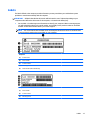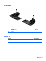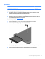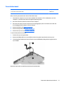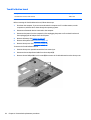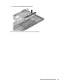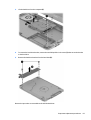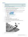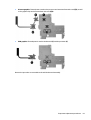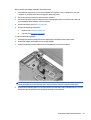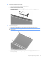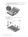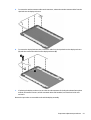
1
HP 15 Notebook PC
Compaq 15 Notebook PC
HP 250 G3 Notebook PC
HP 255 G3 Notebook PC
HP 256 G3 Notebook PC
Maintenance and Service Guide
© Copyright 2013, 2014 Hewlett-Packard
Development Company, L.P.
AMD and Radeon are trademarks of Advanced
Micro Devices, Inc. Bluetooth is a trademark
owned by its proprietor and used by HewlettPackard Company under license. Intel, Celeron,
Core, and Pentium are trademarks of Intel
Corporation in the U.S. and other countries.
Microsoft and Windows are U.S. registered
trademarks of the Microsoft group of
companies. SD Logo is a trademark of
its proprietor.
The information contained herein is subject to
change without notice. The only warranties for
HP products and services are set forth in the
express warranty statements accompanying
such products and services. Nothing herein
should be construed as constituting an
additional warranty. HP shall not be liable for
technical or editorial errors or omissions
contained herein.
Third Edition: May 2014
First Edition: December 2013
Document Part Number: 756246-003
Product notice
This guide describes features that are common
to most models. Some features may not be
available on your computer.
Not all features are available on all editions of
Windows 8. This computer may require
upgraded and/or separately purchased
hardware, drivers, and/or software to take full
advantage of Windows 8 functionality. See
http://www.microsoft.com for details.
This computer may require upgraded and/ or
separately purchased hardware and/or a DVD
drive to install the Windows 7 software and
take full advantage of Windows 7 functionality.
See http://windows.microsoft.com/en-us/
windows7/get-know-windows-7 for details.
Safety warning notice
WARNING! To reduce the possibility of heat-related injuries or of overheating the device, do not place the
device directly on your lap or obstruct the device air vents. Use the device only on a hard, flat surface. Do not
allow another hard surface, such as an adjoining optional printer, or a soft surface, such as pillows or rugs or
clothing, to block airflow. Also, do not allow the AC adapter to contact the skin or a soft surface, such as
pillows or rugs or clothing, during operation. The device and the AC adapter comply with the user-accessible
surface temperature limits defined by the International Standard for Safety of Information Technology
Equipment (IEC 60950).
iii
iv
Safety warning notice
Table of contents
1 Product description ....................................................................................................................................... 1
2 External component identification ................................................................................................................. 7
Display ................................................................................................................................................................... 7
Front ....................................................................................................................................................................... 8
Right side ............................................................................................................................................................... 8
Left side ................................................................................................................................................................. 9
Top ....................................................................................................................................................................... 10
TouchPad ........................................................................................................................................... 10
Lights ................................................................................................................................................. 11
Button ................................................................................................................................................ 12
Keys ................................................................................................................................................... 13
Bottom ................................................................................................................................................................. 14
Labels ................................................................................................................................................................... 15
3 Illustrated parts catalog .............................................................................................................................. 17
Computer major components ............................................................................................................................. 17
Display assembly subcomponents ..................................................................................................................... 28
Mass storage devices .......................................................................................................................................... 30
Plastics Kit ........................................................................................................................................................... 31
Rubber Kit ............................................................................................................................................................ 31
Miscellaneous parts ............................................................................................................................................. 32
Sequential part number listing ........................................................................................................................... 33
4 Removal and replacement procedures ........................................................................................................... 45
Preliminary replacement requirements .............................................................................................................. 45
Tools required ................................................................................................................................... 45
Service considerations ...................................................................................................................... 45
Plastic parts .................................................................................................................... 45
Cables and connectors .................................................................................................... 45
Drive handling ................................................................................................................. 46
Grounding guidelines ........................................................................................................................ 46
Electrostatic discharge damage ..................................................................................... 46
Packaging and transporting guidelines ....................................................... 47
Component replacement procedures ................................................................................................................. 49
Battery ............................................................................................................................................... 49
v
Display subcomponents (bezel, webcam, panel) ............................................................................. 50
Optical drive ...................................................................................................................................... 53
Keyboard ........................................................................................................................................... 55
Top cover ........................................................................................................................................... 58
Power button board .......................................................................................................................... 61
TouchPad button board .................................................................................................................... 62
Hard drive .......................................................................................................................................... 64
WLAN module .................................................................................................................................... 66
Fan ..................................................................................................................................................... 68
Power connector cable ...................................................................................................................... 70
System board .................................................................................................................................... 71
USB board .......................................................................................................................................... 79
Speakers ............................................................................................................................................ 80
Heat sink assembly ........................................................................................................................... 81
RTC battery ........................................................................................................................................ 84
Memory module ................................................................................................................................ 85
Display assembly .............................................................................................................................. 86
5 Using Setup Utility (BIOS) and HP PC Hardware Diagnostics (UEFI) in Windows 8 ............................................... 93
Starting Setup Utility (BIOS) ................................................................................................................................ 93
Updating the BIOS ................................................................................................................................................ 93
Determining the BIOS version ........................................................................................................... 93
Downloading a BIOS update .............................................................................................................. 94
Using HP PC Hardware Diagnostics (UEFI) .......................................................................................................... 95
Downloading HP PC Hardware Diagnostics (UEFI) to a USB device .................................................. 95
6 Using Setup Utility (BIOS) and System Diagnostics in Windows 7 ..................................................................... 97
Starting Setup Utility (BIOS) ................................................................................................................................ 97
Updating the BIOS ................................................................................................................................................ 97
Determining the BIOS version ........................................................................................................... 97
Downloading a BIOS update .............................................................................................................. 98
Using HP PC Hardware Diagnostics (UEFI) .......................................................................................................... 98
Downloading HP PC Hardware Diagnostics (UEFI) to a USB device .................................................. 99
7 Computer Setup (BIOS) and Advanced System Diagnostics in SUSE Linux ........................................................ 101
Starting Computer Setup .................................................................................................................................. 101
Using Computer Setup ....................................................................................................................................... 101
Navigating and selecting in Computer Setup ................................................................................. 101
Restoring factory settings in Computer Setup ............................................................................... 102
Updating the BIOS .............................................................................................................................................. 102
vi
Determining the BIOS version ......................................................................................................... 102
Downloading a BIOS update ........................................................................................................... 103
Using HP PC Hardware Diagnostics (UEFI) ........................................................................................................ 103
Downloading HP PC Hardware Diagnostics (UEFI) to a USB device ............................................... 104
8 Specifications ........................................................................................................................................... 105
Computer specifications .................................................................................................................................... 105
39.6-cm (15.6-in) display specifications .......................................................................................................... 106
Hard drive specifications ................................................................................................................................... 107
DVD±RW SuperMulti DL Drive specifications .................................................................................................... 108
9 Backing up, restoring, and recovering in Windows 8 ..................................................................................... 109
Creating recovery media and backups .............................................................................................................. 109
Creating HP Recovery media ........................................................................................................... 109
Restore and recovery ........................................................................................................................................ 110
Recovering using HP Recovery Manager ........................................................................................ 111
What you need to know ................................................................................................ 111
Using the HP Recovery partition (select models only) ................................................ 111
Using HP Recovery media to recover ........................................................................... 112
Changing the computer boot order .............................................................................. 112
Removing the HP Recovery partition ............................................................................................. 112
10 Backing up, restoring, and recovering in Windows 7 ................................................................................... 113
Creating backups ............................................................................................................................................... 113
Creating recovery media to recover the original system ............................................................... 113
What you need to know ................................................................................................ 113
Creating the recovery media ...................................................................... 114
Creating system restore points ...................................................................................................... 114
What you need to know ................................................................................................ 114
Creating a system restore point ................................................................................... 114
Backing up system and personal information ............................................................................... 114
Tips for a successful backup ........................................................................................ 115
What you need to know ................................................................................................ 115
Creating a backup using Windows Backup and Restore .............................................. 115
Restore and recovery ........................................................................................................................................ 116
Restoring to a previous system restore point ................................................................................ 116
Restoring specific files .................................................................................................................... 116
Restoring specific files using Windows Backup and Restore ...................................... 116
Recovering the original system using HP Recovery Manager ........................................................ 116
What you need to know ................................................................................................ 116
vii
Recovering using HP Recovery partition (select models only) .................................... 117
Recovering using the recovery media .......................................................................... 117
Changing the computer boot order ........................................................... 117
11 Backup and Recovery in SUSE Linux ........................................................................................................... 119
Backing up your information ............................................................................................................................. 119
Performing a system recovery .......................................................................................................................... 119
12 Statement of Volatility ............................................................................................................................ 121
Non-volatile memory usage ............................................................................................................................. 123
Questions and answers ..................................................................................................................................... 125
13 Power cord set requirements .................................................................................................................... 127
Requirements for all countries ......................................................................................................................... 127
Requirements for specific countries and regions ............................................................................................. 128
14 Recycling ................................................................................................................................................ 131
Battery ............................................................................................................................................................... 131
Display ............................................................................................................................................................... 131
Index ........................................................................................................................................................... 137
viii
1
Product description
Category
Description
HP/CPQ 15
(AMD)
HP/CPQ 15
(Intel)
Product name
HP 15 Notebook PC
√
√
Compaq 15 Notebook PC
√
√
HP 255
(AMD)
HP 250 G3 Notebook PC
√
HP 255 G3 Notebook PC
√
HP 256 G3 Notebook PC
Processors
AMD A8-6410 processor (2.0-GHz, 2-MB L2 cache, 1600-MHz
DDR3L
HP 250
(Intel)
√
√
√
√
√
√
AMD A6-6310 processor (1.8-GHz, 2-MB L2 cache, 1600-MHz
DDR3L (not for HP 255 G3 models)
AMD A4-6210 processor (1.8-GHz, 2-MB L2 cache, 1600-MHz
DDR3L
AMD E2-6110 processor (1.5-GHz, 2-MB L2 cache, 1600-MHz
DDR3L
AMD E1-6010 processor (1.35-GHz, 1-MB L2 cache, 1600-MHz
DDR3L
AMD A6-5200 processor (2.0-GHz, 2-MB L2 cache, 1600-MHz
DDR3L)
AMD A4-5000 processor (1.5-GHz, 2-MB L2 cache, 1600-MHz
DDR3L)
AMD E2-3800 processor (1.3-GHz, 2-MB L2 cache, 1600-MHz
DDR3L)
AMD E1-2100 processor (1.0-GHz, 2-MB L2 cache, 1333-MHz
DDR3L)
Intel Core i5-4510U processor (2.0-GHz, 4-MB L2 cache, 1600-MHz
DDR3L)
√
Intel Core i5-4210U processor (1.7-GHz, 3-MB L2 cache, 1600-MHz
DDR3L)
Intel Core i3-4030U processor (1.9-GHz, 3-MB L2 cache, 1600-MHz
DDR3L)
Intel Core i3-4010U processor (1.7-GHz, 3-MB L2 cache, 1600-MHz
DDR3L)
Intel Core i3-4005U processor (1.7-GHz, 3-MB L2 cache, 1600-MHz
DDR3L)
Intel Core i3-3217U processor (1.8-GHz, 3-MB L2 cache, 1600-MHz
DDR3L)
Intel Pentium N3530 processor (2.58-GHz, 2-MB L2 cache, 1333MHz DDR3L)
Intel Pentium N3520 processor (2.17-GHz, 2-MB L2 cache, 1333MHz DDR3L)
1
Category
Description
HP/CPQ 15
(AMD)
HP/CPQ 15
(Intel)
HP 255
(AMD)
HP 250
(Intel)
Integrated SOC FCH
√
√
√
√
Intel HM76 Express Chipset
√
√
Internal graphics:
√
√
√
√
√
√
√
√
√
√
√
√
Intel Celeron N2830 processor (2.42-GHz, 1-MB L2 cache, 1333MHz DDR3L)
Intel Celeron N2815 processor (1.86-GHz, 1-MB L2 cache, 1333MHz DDR3L)
Chipset
Graphics
√
AMD Radeon HD 8400 Graphics (A6-5200)
AMD RadeonT HD 8330 Graphics (A4-5000)
AMD Radeon HD 8280 Graphics (E2-3800)
AMD RadeonT HD 8280 Graphics (E2-3800)
AMD Radeon HD 8210 Graphics (E1-2100)
AMD Radeon R5 Graphics
AMD Radeon R4 Graphics
AMD Radeon R3 Graphics
AMD Radeon R2 Graphics
Switchable discrete graphics:
AMD Sun LE (18W) Radeon HD 8570M with up to 1024MB or 2048
MB of dedicated video memory
Internal graphics:
√
Intel HD Graphics 4400
Intel HD Graphics 4000
External graphics:
Nvidia 820M N15V-GM 1 GB VRAM
Nvidia 820M N15V-GM 2 GB VRAM (HP 15/Compaq 15 only)
GPU power management enabled at launch
Support DX11
Support dynamic switching
Support HD Decode and HDMI
Panel
39.6-cm (15.6-in), high-definition (HD), light-emitting diode (LED),
SVA BrightView (1366×768) display, flat 3.8 mm; typical
brightness: 200 nits
√
√
Touch screen, multi-touch enabled
Supports LVDS
Memory
Intel models:
1 or 2 customer-accessible/upgradable memory module slots
(depending on model)
Supports single-channel memory
2
Chapter 1 Product description
√
Category
Description
HP/CPQ 15
(AMD)
HP/CPQ 15
(Intel)
HP 255
(AMD)
HP 250
(Intel)
√
√
√
√
√
√
√
√
√
√
√
√
√
√
√
DDR3L-1600-MHz Single Channel Support
DDR3L-1333-MHz Single Channel Support (DDR3-1600 downgrade
to DDR3-1333)
Supports up to 16 GB of system RAM in the following
configurations:
●
16384-MB total system memory (8192×2)
●
12288-MB total system memory (8192×1 + 4096×1)
●
8192-MB total system memory (8192×1) or (4096×2)
●
6144-MB total system memory (4096×1 + 2048×1)
●
4096-MB total system memory (4096×1) or (2048×2)
●
2048-MB total system memory (2048×1)
AMD models:
1 customer-accessible/upgradable memory module slot
Supports single-channel memory
DDR3L-1600-MHz Single Channel Support
DDR3L-1333-MHz Single Channel Support (DDR3-1600 downgrade
to DDR3-1333)
Supports up to 8 GB of system RAM in the following
configurations:
Hard drives
●
8192-MB total system memory (8192×1) or (4096×2)
●
4096-MB total system memory (4096×1) or (2048×2)
●
2048-MB total system memory (2048×1)
Supports 6.35-cm (2.5-in) hard drives in 9.5-mm (.37-in) and 7.0mm (.28-in) thicknesses
Serial ATA
Supports the following hard drives:
●
1-TB, 5400-rpm, 9.5-mm
●
750-GB, 5400-rpm, 9.5-mm
●
500-GB, 7200-rpm, 7.0-mm (HP 250 G3 models only)
500-GB, 5400-rpm, 9.5-mm or 7.0-mm
●
Optical drive
320-GB, 5400-rpm, 9.5-mm or 7.0-mm
Fixed, serial ATA, 9.5-mm tray load
DVD+/-RW Double-Layer SuperMulti
Supports zero power optical drive
Audio/video
Single digital microphone
HD audio
Dual speakers
HP Webcam (fixed, no tilt with activity LED, 640×480 by 24 frames
per second)
3
Category
Description
Ethernet
Integrated 10/100 network interface card (NIC)
HP/CPQ 15
(AMD)
HP/CPQ 15
(Intel)
HP 255
(AMD)
HP 250
(Intel)
√
√
√
√
√
√
√
√
√
√
√
√
√
√
√
√
√
√
√
√
√
√
√
√
Integrated 10/100/1000 network interface card (NIC) (UMA, nontouch models only)
Wireless
Integrated wireless local area network (WLAN) options by way of
wireless module
One or two WLAN antennas built into display assembly
Compatible with Miracast-certified devices
Single antenna support
Support for the following WLAN formats:
External
media card
●
Realtek RTL8188EE 802.11bgn 1x1 Wi-Fi Adapter
●
Qualcomm Atheros AR9485 802.11bgn 1x1 Wi-Fi Adapter
●
Ralink RT3290LE 802.11bgn 1x1 Wi-Fi + BT 4.0 Combo
Adapter
●
QCA 9565 802.11bgn 1x1 Wi-Fi + BT4.0 Combo Adapter
HP Multi-Format Digital Media Reader
Support SD/SDHC/SDXC
Push-Pull Insertion/Removal
Ports
HDMI version 1.4 supporting 1920 ×1200 @ 60Hz
Hot Plug/unplug and auto detect for correct output to wide-aspect
vs. standard aspect video
RJ-45 (Ethernet, includes link and activity lights)
USB 3.0 (1 port)
USB 2.0 (2 ports)
AC Smart Pin adapter plug
Headphone/microphone in combo jack
Keyboard/
pointing
devices
Full-size "island style" keyboard with numeric keypad
TouchPad with multi-touch gestures, 2-finger scrolling, and pinchzoom enabled
Taps enabled by default
Support Win8.1+D212 Modern Trackpad Gestures
Support PS/2, profile sensor (reserve for SMBus)
Power
requirements
AC adapters:
AC Adapter 65-W Smart nPFC, 3 pin, RC 4.5mm connector - non
slim for use in discrete models
AC Adapter 45-W Smart nPFC, 3 pin, RC 4.5mm connector - non
slim for use in UMA models
AC Adapter 65-W EM Smart nPFC, 3 pin, RC 4.5mm connector, 90
degree plug design for use in India/China
1 meter power cord
4
Chapter 1 Product description
Category
Description
4-cell, 41-Whr Li-ion battery
HP/CPQ 15
(AMD)
HP/CPQ 15
(Intel)
HP 255
(AMD)
HP 250
(Intel)
√
√
√
√
√
√
√
√
√
√
√
√
√
√
√
√
3-cell, 31-Whr Li-ion battery
Security
Kensington Security Lock
Support Intel Anti-Theft
Support Intel IPT
OTP support
Operating
system
Serviceability
Preinstalled:
●
Windows 8.1
●
Ubuntu
●
FreeDOS 2.0
End-user replaceable parts:
●
AC adapter
●
Battery
●
Optical drive
●
Keyboard
5
6
Chapter 1 Product description
2
External component identification
Display
Component
Description
(1)
WLAN antennas (1 or 2)* (select models only)
Send and receive wireless signals to communicate with wireless local
area networks (WLANs).
(2)
WWAN antennas (1 or 2)* (select models only)
Send and receive wireless signals to communicate with wireless wide
area networks (WWAN).
(3)
Webcam light
On: The webcam is in use.
(4)
Webcam
Records video and captures photographs. Some models allow you to
video conference and chat online using streaming video.
To use the webcam in Windows 8, from the Start screen, type
camera, and then select Camera from the list of applications.
(5)
Internal microphone
Records sound.
(6)
Internal display switch
Turns off the display and initiates Sleep if the display is closed while
the power is on.
NOTE: The internal display switch is not visible from the outside of
the computer.
*The antennas are not visible from the outside of the computer. For optimal transmission, keep the areas immediately around the
antennas free from obstructions. For wireless regulatory notices, see the section of the Regulatory, Safety, and Environmental Notices
that applies to your country or region. To access this guide in Windows 8, from the Start screen, type support, and then select the
HP Support Assistant app.
Display
7
Front
Component
Description
Memory card reader
Reads optional memory cards that store, manage,
share, or access information.
To insert a card:
Hold the card label-side up, with connectors facing the
slot, insert the card into the slot, and then push in on the
card until it is firmly seated.
To remove a card:
Pull the card out of the slot.
Right side
Component
Description
(1)
USB 2.0 ports (2)
Connect an optional USB device, such as a keyboard,
mouse, external drive, printer, scanner or USB hub.
(2)
Optical drive (select models only)
Depending on your computer model, reads an optical
disc or reads and writes to an optical disc.
NOTE: For disc compatibility information, go to the
Help and Support web page. Follow the web page
instructions to select your computer model. Select
Support & Drivers, and then select Product
Information.
(3)
8
Optical drive eject button (select models
only)
Chapter 2 External component identification
Releases the disc tray.
Left side
Component
(1)
Description
Security cable slot
Attaches an optional security cable to the computer.
NOTE: The security cable is designed to act as a deterrent, but
it may not prevent the computer from being mishandled or
stolen.
(2)
Power connector
Connects an AC adapter.
(3)
AC adapter light
●
On: The AC adapter is connected and the battery is
charged.
●
Off: The computer is using battery power.
(4)
Vent
Enables airflow to cool internal components.
NOTE: The computer fan starts up automatically to cool
internal components and prevent overheating. It is normal for
the internal fan to cycle on and off during routine operation.
(5)
External monitor port (select models only)
Connects an external VGA monitor or projector.
(6)
HDMI port
Connects an optional video or audio device, such as a highdefinition television, any compatible digital or audio
component, or a high-speed HDMI device.
(7)
RJ-45 (network) jack/status lights
Connects a network cable.
●
White: The network is connected.
●
Amber: Activity is occurring on the network.
(8)
USB 3.0 port
Connects an optional USB device, such as a keyboard, mouse,
external drive, printer, scanner or USB hub.
(9)
Audio-out (headphone)/Audio-in (microphone)
jack
Connects optional powered stereo speakers, headphones,
earbuds, a headset, or a television audio cable. Also connects an
optional headset microphone. This jack does not support
optional microphone-only devices.
WARNING! To reduce the risk of personal injury, adjust the
volume before putting on headphones, earbuds, or a headset.
For additional safety information, refer to the Regulatory,
Safety, and Environmental Notices. To access this guide in
Windows 8, from the Start screen, type support, and then
select the HP Support Assistant app.
NOTE: When a device is connected to the jack, the computer
speakers are disabled.
Left side
9
Component
Description
NOTE: Be sure that the device cable has a 4-conductor
connector that supports both audio-out (headphone) and audioin (microphone).
(10)
Hard drive light
Blinking white: The hard drive is being accessed.
(11)
Power light
●
On: The computer is on.
●
Blinking: The computer is in the Sleep state, a powersaving state. The computer shuts off power to the display
and other unneeded components.
●
Off: The computer is off or in Hibernation. Hibernation is a
power-saving state that uses the least amount of power.
Top
TouchPad
Component
(1)
Description
TouchPad zone
Moves the on-screen pointer and selects or activates items on
the screen.
NOTE:
10
The TouchPad also supports edge-swipe gestures.
(2)
Left TouchPad button
Functions like the left button on an external mouse.
(3)
Right TouchPad button
Functions like the right button on an external mouse.
Chapter 2 External component identification
Lights
Component
(1)
Description
Power light
●
On: The computer is on.
●
Blinking: The computer is in the Sleep state, a powersaving state. The computer shuts off power to the display
and other unneeded components.
●
Off: The computer is off or in Hibernation. Hibernation is a
power-saving state that uses the least amount of power.
(2)
Caps lock light
On: Caps lock is on, which switches the keys to all capital letters.
(3)
Mute light
●
Amber: Computer sound is off.
●
Off: Computer sound is on.
(4)
Wireless light
On: An integrated wireless device, such as a wireless local area
network (WLAN) device and/or a Bluetooth® device, is on.
NOTE: On some models, the wireless light is amber when all
wireless devices are off.
Top
11
Button
Component
Description
Power button
●
When the computer is off, press the button to turn on the
computer.
●
When the computer is on, press the button briefly to
initiate Sleep.
●
When the computer is in the Sleep state, press the button
briefly to exit Sleep.
●
When the computer is in Hibernation, press the button
briefly to exit Hibernation.
CAUTION: Pressing and holding down the power button will
result in the loss of unsaved information.
If the computer has stopped responding and shutdown
procedures are ineffective, press and hold the power button
down for at least 5 seconds to turn off the computer.
To learn more about your power settings, see your power
options. In Windows 8, from the Start screen, type power,
select Power and sleep settings, and then select Power and
sleep from the list of applications.
12
Chapter 2 External component identification
Keys
Component
Description
(1)
esc key
Displays system information when pressed in combination with
the fn key.
(2)
fn key
Executes frequently used system functions when pressed in
combination with the spacebaror the esc key.
(3)
Windows key
(Windows 8) Returns you to the Start screen from an open app
or the Windows desktop.
NOTE: Pressing the Windows key again will return you to the
previous screen.
(4)
Action keys
Execute frequently used system functions.
(5)
num lk key
Alternates between the navigational and numeric functions on
the integrated numeric keypad.
NOTE: The keypad function that is active when the computer
is turned off is reinstated when the computer is turned back on.
(6)
Integrated numeric keypad
When num lk has been enabled, it can be used like an external
numeric keypad. To alternate between this numeric function
and the navigational function (indicated by the directional
arrows on the keys), press the num lk key.
Top
13
Bottom
Component
Description
(1)
Battery lock and unlock latch
Locks and unlocks the battery in the battery bay.
(2)
Battery bay
Holds the battery.
(3)
Vent
Enable airflow to cool internal components.
NOTE: The computer fan starts up automatically to cool
internal components and prevent overheating. It is normal
for the internal fan to cycle on and off during routine
operation.
14
(4)
Battery release latch
Releases the battery.
(5)
Speaker openings (2)
Produce sound.
Chapter 2 External component identification
Labels
The labels affixed to the computer provide information you may need when you troubleshoot system
problems or travel internationally with the computer.
IMPORTANT: All labels described in this section will be located in one of 2 places depending on your
computer model: Affixed to the bottom of the computer, or located in the battery bay.
●
Service label—Provides important information to identify your computer. When contacting support,
you will probably be asked for the serial number, and possibly for the product number or the model
number. Locate these numbers before you contact support.
NOTE: Your service labels will resemble one of the examples shown below. Refer to the illustration
that most closely matches the service label on your computer.
Component
(1)
Product name
(2)
Serial number
(3)
Product number
(4)
Warranty period
(5)
Model number (select models only)
Component
(1)
Serial number
(2)
Product number
(3)
Warranty period
Labels
15
Component
16
(4)
Model number (select models only)
(5)
Revision number
●
Regulatory label(s)—Provide(s) regulatory information about the computer.
●
Wireless certification label(s)—Provide(s) information about optional wireless devices and the approval
markings for the countries or regions in which the devices have been approved for use.
Chapter 2 External component identification
3
Illustrated parts catalog
Computer major components
NOTE: HP continually improves and changes product parts. For complete and current information on
supported parts for your computer, go to http://partsurfer.hp.com, select your country or region, and then
follow the on-screen instructions.
Computer major components
17
Item
Component
(1)
Display assembly (39.6-cm [15.6-in] HD, anti-glare, touchscreen)
NOTE:
(2)
18
Spare part number
For display assembly spare part information, see Display assembly subcomponents on page 28.
Keyboard
Chapter 3 Illustrated parts catalog
Item
(3)
Component
Spare part number
For use in the United States
749658-001
For use in the United Kingdom
749658-031
For use in Germany
749658-041
For use in France
749658-051
For use in Italy
749658-061
For use in Spain
749658-071
For use in Portugal
749658-131
For use in Turkey
749658-141
For use in Greece
749658-151
For use in Latin America
749658-161
For use in Saudi Arabia
749658-171
For use in Hungary
749658-211
For use in Russia
749658-251
For use in Bulgaria
749658-261
For use in Romania
749658-271
For use in Thailand
749658-281
For use in Japan
749658-291
For use in Belgium
749658-A41
For use in Taiwan
749658-AB1
For use in South Korea
749658-AD1
For use in the Netherlands
749658-B31
For use in Slovenia
749658-BA1
For use in Israel
749658-BB1
For use in Switzerland
749658-BG1
For use in French Canada
749658-DB1
For use in Denmark, Finland, and Norway
749658-DH1
For use in the Czech Republic and Slovakia
749658-FL1
Top cover (includes touchpad)
Black HP 15 models
749639-001
Purple HP 15 models
775088-001
Sparkling black HP 15 models
768276-001
Red HP 15 models
760958-001
White HP 15 models
760959-001
Blue HP 15 models
760960-001
Computer major components
19
Item
Component
Spare part number
Silver HP 15 models
760961-001
Gray Compaq 15 models
749640-001
HP 250/255 G3 models
754214-001
(4)
Power button board (includes cable)
749650-001
(5)
Touchpad button board (includes bracket)
749651-001
(6)
WLAN module:
Atheros AR9485 802.11b/g/n 1x1 WiFi Adapter
675794-001
Ralink RT3290LE 802.11bgn 1x1 Wi-Fi and Bluetooth 4.0 Combo Adapter
690020-001
Atheros AR9565 802.11bgn 1x1 WiFi + BT4.0 combo Adapter
733476-001
Realtek RTL8188EE 802.11bgn Wi-Fi Adapter
709848-001
(7)
USB board (includes cable)
749649-001
(8)
System board (includes replacement thermal materials):
For use in HP 15 and Compaq 15 models:
20
●
AMD A8-6410 processor and UMA graphics in touch screen models without Windows 8
764261-001
●
AMD A8-6410 processor and UMA graphics in touch screen models with Windows 8
Standard
764261-501
●
AMD A8-6410 processor and UMA graphics in touch screen models with Windows 8
Professional
764261-601
●
AMD A6-6310 processor and UMA graphics in touch screen models without Windows 8
764263-001
●
AMD A6-6310 processor and UMA graphics in touch screen models with Windows 8
Standard
764263-501
●
AMD A6-6310 processor and UMA graphics in touch screen models with Windows 8
Professional
764263-601
●
AMD A4-6210 processor and UMA graphics in touch screen models without Windows 8
764265-001
●
AMD A4-6210 processor and UMA graphics in touch screen models with Windows 8
Standard
764265-501
●
AMD A4-6210 processor and UMA graphics in touch screen models with Windows 8
Professional
764265-601
●
AMD E2-6110 processor and UMA graphics in models without Windows 8
764266-001
●
AMD E2-6110 processor and UMA graphics in models with Windows 8 Standard
764266-501
●
AMD E2-6110 processor and UMA graphics in models with Windows 8 Professional
764266-601
●
AMD A6-5200 processor and UMA graphics in models without Windows 8
760149-001
●
AMD A6-5200 processor and UMA graphics in models with Windows 8 Standard
760149-501
●
AMD A6-5200 processor and UMA graphics in models with Windows 8 Professional
760149-601
●
AMD A6-5200 processor and UMA graphics in touch screen models without Windows 8
762735-001
●
AMD A6-5200 processor and UMA graphics in touch screen models with Windows 8
Standard
762735-501
Chapter 3 Illustrated parts catalog
Item
Component
Spare part number
●
AMD A6-5200 processor and UMA graphics in touch screen models with Windows 8
Professional
762735-601
●
AMD A4-5000 processor in models with 2 GB of discrete graphics, without Windows 8
760155-001
●
AMD A4-5000 processor in models with 2 GB of discrete graphics and with Windows 8
Standard
760155-501
●
AMD A4-5000 processor in models with 2 GB of discrete graphics and with Windows 8
Professional
760155-601
●
AMD A4-5000 processor and UMA graphics in models without Windows 8
750634-001
●
AMD A4-5000 processor and UMA graphics in models with Windows 8 Standard
750634-501
●
AMD A4-5000 processor and UMA graphics in models with Windows 8 Professional
750634-601
●
AMD A4-5000 processor and UMA graphics in touch screen models without Windows 8
762734-001
●
AMD A4-5000 processor and UMA graphics in touch screen models with Windows 8
Standard
762734-501
●
AMD A4-5000 processor and UMA graphics in touch screen models with Windows 8
Professional
762734-601
●
AMD E2-3800 processor and UMA graphics in models without Windows 8
749659-001
●
AMD E2-3800 processor and UMA graphics in models with Windows 8 Standard
749659-501
●
AMD E2-3800 processor and UMA graphics in models with Windows 8 Professional
749659-601
●
AMD E1-2100 processor and UMA graphics in models without Windows 8
750633-001
●
AMD E1-2100 processor and UMA graphics in models with Windows 8 Standard
750633-501
●
AMD E1-2100 processor and UMA graphics in models with Windows 8 Professional
750633-601
For use in HP 255 G3 models:
●
AMD A8-6410 processor and UMA graphics in models without Windows 8 (touch
screen)
764000-001
●
AMD A8-6410 processor and UMA graphics in models with Windows 8 Standard (touch
screen)
764000-501
●
AMD A8-6410 processor and UMA graphics in models with Windows 8 Professional
(touch screen)
764000-601
●
AMD A8-6410 processor and UMA graphics in models without Windows 8
763999-001
●
AMD A8-6410 processor and UMA graphics in models with Windows 8 Standard
763999-501
●
AMD A8-6410 processor and UMA graphics in models with Windows 8 Professional
763999-601
●
AMD A4-6210 processor and UMA graphics in models without Windows 8
764001-001
●
AMD A4-6210 processor and UMA graphics in models with Windows 8 Standard
764001-501
●
AMD A4-6210 processor and UMA graphics in models with Windows 8 Professional
764001-601
●
AMD A4-6210 processor and 1 GB of discrete graphics memory in models without
Windows 8
764004-001
●
AMD A4-6210 processor and 1 GB of discrete graphics memory in models with
Windows 8 Standard
764004-501
Computer major components
21
Item
Component
Spare part number
●
AMD A4-6210 processor and 1 GB of discrete graphics memory in models with
Windows 8 Professional
764004-601
●
AMD E2-6110 processor and UMA graphics in models without Windows 8
764002-001
●
AMD E2-6110 processor and UMA graphics in models with Windows 8 Standard
764002-501
●
AMD E2-6110 processor and UMA graphics in models with Windows 8 Professional
764002-601
●
AMD E1-6010 processor and UMA graphics in models without Windows 8
764003-001
●
AMD E1-6010 processor and UMA graphics in models with Windows 8 Standard
764003-501
●
AMD E1-6010 processor and UMA graphics in models with Windows 8 Professional
764003-601
●
AMD A6-5200 processor and UMA graphics in models without Windows 8 (touch
screen)
763021-001
●
AMD A6-5200 processor and UMA graphics in models with Windows 8 Standard (touch
screen)
763021-501
●
AMD A6-5200 processor and UMA graphics in models with Windows 8 Professional
(touch screen)
763021-601
●
AMD A6-5200 processor and UMA graphics in models without Windows 8
761533-001
●
AMD A6-5200 processor and UMA graphics in models with Windows 8 Standard
761533-501
●
AMD A6-5200 processor and UMA graphics in models with Windows 8 Professional
761533-601
●
AMD A4-5000 processor and 1 GB of discrete graphics memory in models without
Windows 8
761534-001
●
AMD A4-5000 processor and 1 GB of discrete graphics memory in models with
Windows 8 Standard
761534-501
●
AMD A4-5000 processor and 1 GB of discrete graphics memory in models with
Windows 8 Professional
761534-601
●
AMD A4-5000 processor and UMA graphics in models without Windows 8
761532-001
●
AMD A4-5000 processor and UMA graphics in models with Windows 8 Standard
761532-501
●
AMD A4-5000 processor and UMA graphics in models with Windows 8 Professional
761532-601
●
AMD E2-3800 processor and UMA graphics in models without Windows 8
761530-001
●
AMD E2-3800 processor and UMA graphics in models with Windows 8 Standard
761530-501
●
AMD E2-3800 processor and UMA graphics in models with Windows 8 Professional
761530-601
●
AMD E1-2100 processor and UMA graphics in models without Windows 8
761531-001
●
AMD E1-2100 processor and UMA graphics in models with Windows 8 Standard
761531-501
●
AMD E1-2100 processor and UMA graphics in models with Windows 8 Professional
761531-601
For use in HP 15 and Compaq 15 models:
22
●
Intel Celeron N2815 processor and UMA graphics memory in models without Windows
8
759879-001
●
Intel Celeron N2815 processor and UMA graphics memory in models with Windows 8
Standard
759879-501
●
Intel Celeron N2815 processor and UMA graphics memory in models with Windows 8
Professional
759879-601
Chapter 3 Illustrated parts catalog
Item
Component
Spare part number
●
Intel Celeron N2830 processor and UMA graphics memory in models without Windows
8
764104-001
●
Intel Celeron N2830 processor and UMA graphics memory in models with Windows 8
Standard
764104-501
●
Intel Celeron N2830 processor and UMA graphics memory in models with Windows 8
Professional
764104-601
●
Intel Pentium N3520 processor and UMA graphics memory in models without Windows
8
759878-001
●
Intel Pentium N3520 processor and UMA graphics memory in models with Windows 8
Standard
759878-501
●
Intel Pentium N3520 processor and UMA graphics memory in models with Windows 8
Professional
759878-601
●
Intel Pentium N3530 processor and UMA graphics memory in models without Windows
8
764103-001
●
Intel Pentium N3530 processor and UMA graphics memory in models with Windows 8
Standard
764103-501
●
Intel Pentium N3530 processor and UMA graphics memory in models with Windows 8
Professional
764103-601
●
Intel Core i3-3217U processor and 2 GB of discrete graphics memory in models
without Windows 8
760969-001
●
Intel Core i3-3217U processor and 2 GB of discrete graphics memory in models with
Windows 8 Standard
760969-501
●
Intel Core i3-3217U processor and 2 GB of discrete graphics memory in models with
Windows 8 Professional
760969-601
●
Intel Core i3-3217U processor and 1 GB of discrete graphics memory in models
without Windows 8
759874-001
●
Intel Core i3-3217U processor and 1 GB of discrete graphics memory in models with
Windows 8 Standard
759874-501
●
Intel Core i3-3217U processor and 1 GB of discrete graphics memory in models with
Windows 8 Professional
759874-601
●
Intel Core i3-3217U processor and UMA graphics memory in models without Windows
8
759873-001
●
Intel Core i3-3217U processor and UMA graphics memory in models with Windows 8
Standard
759873-501
●
Intel Core i3-3217U processor and UMA graphics memory in models with Windows 8
Professional
759873-601
●
Intel Core i3-4005U processor and UMA graphics in models without Windows 8
765444-001
●
Intel Core i3-4005U processor and UMA graphics in models with Windows 8 Standard
765444-501
●
Intel Core i3-4005U processor and UMA graphics in models with Windows 8
Professional
765444-601
●
Intel Core i3-4005U processor and 1 GB of discrete graphics in models without
Windows 8
775393-001
●
Intel Core i3-4005U processor and 1 GB of discrete graphics in models with Windows 8
Standard
775393-501
Computer major components
23
Item
Component
Spare part number
●
Intel Core i3-4005U processor and 1 GB of discrete graphics in models with Windows 8
Professional
775393-601
●
Intel Core i3-4005U processor and 2 GB of discrete graphics in models without
Windows 8
775394-001
●
Intel Core i3-4005U processor and 2 GB of discrete graphics in models with Windows 8
Standard
775394-501
●
Intel Core i3-4005U processor and 2 GB of discrete graphics in models with Windows 8
Professional
775394-601
●
Intel Core i3-4010U processor and UMA graphics in models without Windows 8
759875-001
●
Intel Core i3-4010U processor and UMA graphics in models with Windows 8 Standard
759875-501
●
Intel Core i3-4010U processor and UMA graphics in models with Windows 8
Professional
759875-601
●
Intel Core i3-4010U processor and 1 GB of discrete graphics memory in models
without Windows 8
759876-001
●
Intel Core i3-4010U processor and 1 GB of discrete graphics memory in models with
Windows 8 Standard
759876-501
●
Intel Core i3-4010U processor and 1 GB of discrete graphics memory in models with
Windows 8 Professional
759876-601
●
Intel Core i3-4010U processor and 2 GB of discrete graphics memory in models
without Windows 8
759877-001
●
Intel Core i3-4010U processor and 2 GB of discrete graphics memory in models with
Windows 8 Standard
759877-501
●
Intel Core i3-4010U processor and 2 GB of discrete graphics memory in models with
Windows 8 Professional
759877-601
●
Intel Core i5-4210U processor and UMA graphics in models without Windows 8
760968-001
●
Intel Core i5-4210U processor and UMA graphics in models with Windows 8 Standard
760968-501
●
Intel Core i5-4210U processor and UMA graphics in models with Windows 8
Professional
760968-601
●
Intel Core i5-4210U processor and 2 GB of discrete graphics memory in models
without Windows 8
760970-001
●
Intel Core i5-4210U processor and 2 GB of discrete graphics memory in models with
Windows 8 Standard
760970-501
●
Intel Core i5-4210U processor and 2 GB of discrete graphics memory in models with
Windows 8 Professional
760970-601
For use in HP 250 G3 models:
24
●
Intel Celeron N2815 processor and UMA graphics memory in models without Windows
8
761543-001
●
Intel Celeron N2815 processor and UMA graphics memory in models with Windows 8
Standard
761543-501
●
Intel Celeron N2815 processor and UMA graphics memory in models with Windows 8
Professional
761543-601
●
Intel Celeron N2830 processor and UMA graphics memory in models without Windows
8
774711-001
Chapter 3 Illustrated parts catalog
Item
Component
Spare part number
●
Intel Celeron N2830 processor and UMA graphics memory in models with Windows 8
Standard
774711-501
●
Intel Celeron N2830 processor and UMA graphics memory in models with Windows 8
Professional
774711-601
●
Intel Pentium N3520 processor and UMA graphics memory in models without Windows
8
761541-001
●
Intel Pentium N3520 processor and UMA graphics memory in models with Windows 8
Standard
761541-501
●
Intel Pentium N3520 processor and UMA graphics memory in models with Windows 8
Professional
761541-601
●
Intel N3530 processor and UMA graphics memory in models without Windows 8
774712-001
●
Intel N3530 processor and UMA graphics memory in models with Windows 8 Standard
774712-501
●
Intel N3530 processor and UMA graphics memory in models with Windows 8
Professional
774712-601
●
Intel Core i3-3217U processor and UMA graphics memory in models without Windows
8
761537-001
●
Intel Core i3-3217U processor and UMA graphics memory in models with Windows 8
Standard
761537-501
●
Intel Core i3-3217U processor and UMA graphics memory in models with Windows 8
Professional
761537-601
●
Intel Core i3-3217U processor and UMA graphics memory in models without Windows
8 and WWAN
761538-001
●
Intel Core i3-3217U processor and UMA graphics memory in models with Windows 8
Standard and WWAN
761538-501
●
Intel Core i3-3217U processor and UMA graphics memory in models with Windows 8
Professional and WWAN
761538-601
●
Intel Core i3-3217U processor and 1 GB of discrete graphics memory in models
without Windows 8
761540-001
●
Intel Core i3-3217U processor and 1 GB of discrete graphics memory in models with
Windows 8 Standard
761540-501
●
Intel Core i3-3217U processor and 1 GB of discrete graphics memory in models with
Windows 8 Professional
761540-601
●
Intel Core i3-4005U processor and UMA graphics memory in models without Windows
8
774716-001
●
Intel Core i3-4005U processor and UMA graphics memory in models with Windows 8
Standard
774716-501
●
Intel Core i3-4005U processor and UMA graphics memory in models with Windows 8
Professional
774716-601
●
Intel Core i3-4005U processor and UMA graphics memory in models without Windows
8
774715-001
●
Intel Core i3-4005U processor and UMA graphics memory in touch screen models with
Windows 8 Standard
774715-501
●
Intel Core i3-4005U processor and UMA graphics memory in touch screen models with
Windows 8 Professional
774715-601
Computer major components
25
Item
(9)
Component
Spare part number
●
Intel Core i3-4005U processor and 1 GB of discrete graphics memory in models
without Windows 8
774714-001
●
Intel Core i3-4005U processor and 1 GB of discrete graphics memory in models with
Windows 8 Standard
774714-501
●
Intel Core i3-4005U processor and 1 GB of discrete graphics memory in models with
Windows 8 Professional
774714-601
●
Intel Core i3-4010U processor and 1 GB of discrete graphics memory in touch screen
models without Windows 8
763752-001
●
Intel Core i3-4010U processor and 1 GB of discrete graphics memory in touch screen
models with Windows 8 Standard
763752-501
●
Intel Core i3-4010U processor and 1 GB of discrete graphics memory in touch screen
models with Windows 8 Professional
763752-601
●
Intel Core i3-4010U processor and UMA graphics memory in models without Windows
8 and WWAN
761536-001
●
Intel Core i3-4010U processor and UMA graphics memory in models with Windows 8
Standard and WWAN
761536-501
●
Intel Core i3-4010U processor and UMA graphics memory in models with Windows 8
Professional and WWAN
761536-601
●
Intel Core i5-4210U processor and UMA graphics memory in models without Windows
8 and WWAN
761535-001
●
Intel i5-4210U processor and UMA graphics memory in models with Windows 8
Standard and WWAN
761535-501
●
Intel i5-4210U processor and UMA graphics memory in models with Windows 8
Professional and WWAN
761535-601
Heat sink assembly (includes replacement thermal materials):
For use in models with an AMD processor and UMA graphics
753895-001
For use in models with an AMD processor and discrete graphics
762728-001
For use in models with an Intel processor and UMA graphics
759880-001
NOTE:
i3-3227U processors use 767539-001
For use in models with an Intel processor and discrete graphics
NOTE:
i3-3227U processors use 767538-001
For use in models with Intel Pentium or Celeron processors and UMA graphics
767537-001
For use in models with Intel i3-3217U processors and discrete graphics
767538-001
For use in models with Intel i3-3217U processors and UMA graphics
767539-001
(10)
RTC battery
759981-001
(11)
Memory module (PC3L, 12800, 1600-MHz):
(12)
26
759881-001
8-GB
693374-001
4 GB
691740-001
2 GB
691739-001
Hard drive (SATA; does not include bracket):
Chapter 3 Illustrated parts catalog
Item
Component
NOTE:
Spare part number
The hard drive bracket is available using spare part number 749648-001.
1-GB, 5400-rpm, 2.5-in
676521-001
750 GB, 5400 rpm hard drive, 2.5 in (for use in HP 250/255 G3 models)
634250-001
500-GB, 5400-rpm
669299-001
320-GB, 5400-rpm, 2.5-in (for use only in HP 250 models)
622643-001
(13)
Fan
753894-001
(14)
Power connector cable
749647-001
(15)
Speakers (includes left and right speakers and cable)
749653-001
(16)
Battery:
(17)
(18)
4-cell, 41-Whr, 2.8-Ah Li-ion battery
740715-001
3-cell, 31-Whr, 2.8-Ah Li-ion battery
746641-001
Base enclosure
For use in defeatured HP 15 and Compaq 15 models
749643-001
For use in full-featured HP 15 and Compaq 15 models
775087-01
For use in HP 250/255 G3 models
754213-001
Optical drive (DVD+/-RW Double-Layer SuperMulti)
750636-001
Computer major components
27
Display assembly subcomponents
Item
Component
(1)
Display bezel (includes Mylar screw covers):
(2)
For use with HP models
749644-001
For use with Compaq models
749645-001
Display cable (includes display panel cable and webcam/microphone cable)
Non-touch screen
749646-001
Touch screen
764888-001
(3)
Webcam/microphone module
749654-001
(4)
Antennas (includes wireless antenna cables and transceivers)
(5)
(6)
28
Spare part number
For use in HP 15 and Compaq 15 models
749638-001
For use in models with a touch screen
774163-001
Hinges (left and right)
749655-001
For use in models without a touch screen
749655-001
For use in models with a touch screen
774166-001
Raw display panel (39.6-cm [15.6-in], HD, WLED, BrightView)
Chapter 3 Illustrated parts catalog
Item
(7)
Component
Spare part number
For use in HP 15 and Compaq 15 models, non-touch screen
750635-001
For use in HP 15 models, touch screen
764877-001
For use in Compaq 15 models, touch screen
764876-001
For use in HP 255 G3 models, touch screen
774167-001
For use in HP 250 G3 models, touch screen
774165-001
Display enclosure:
For use in black HP 15 models
749641-001
For use in black Compaq 15 models
760962-001
For use in black touch screen models (all models)
774164-001
For use in sparkling black HP 15 models
761695-001
For use in sparkling black HP 15 touch screen models
775086-001
For use in gray Compaq 15 models
749642-001
For use in gray HP 15 models
760963-001
For use in red HP 15 models
760964-001
For use in red HP 15 touch screen models
775082-001
For use in white HP 15 models
760965-001
For use in white HP 15 touch screen models
775083-001
For use in blue HP 15 models
760966-001
For use in blue HP 15 touch screen models
775084-001
For use in silver HP 15 models
760967-001
For use in silver HP 15 touch screen models
775085-001
For use in purple HP 15 models
775089-001
Display assembly subcomponents
29
Mass storage devices
30
Item
Component
Spare part number
(1)
Optical drive (DVD+/-RW Double-Layer SuperMulti)
750636-001
(2)
Hard drive, SATA; does not include bracket):
1-GB, 5400-rpm, 2.5-in
676521-001
750 GB, 5400 rpm hard drive, 2.5 in (for use in HP 250/255 G3 models)
634250-001
500-GB, 5400-rpm
669299-001
320-GB, 5400-rpm, 2.5-in (for use only in HP 250 models)
622643-001
Hard drive bracket
749648-001
Chapter 3 Illustrated parts catalog
Plastics Kit
Item
Component
Spare part number
Plastics Kit, includes:
749656-001
(1)
Left cover
(2)
Right cover
Rubber Kit
Component
Spare part number
Rubber Kit, includes:
749652-001
Front feet
Rear feet
Plastics Kit
31
Miscellaneous parts
Component
Spare part number
HP Smart AC adapter:
65-W non-PFC EM HP Smart AC adapter (for use in the People’s Republic of China and India only)
714657-001
AC adapter, 65-W, non-PFC, 4.5 mm
710412-001
45-W non-PFC, non-slim HP Smart AC adapter (for use in all countries and regions except for the
People’s Republic of China and India)
741427-001
Power cord (3-pin, black, 1.83-m):
For use in models with AMD processors:
●
For use in Australia
490371-011
●
For use in Europe, the Middle East, and Africa
490371-021
●
For use in India
490371-D61
●
For use in Italy
490371-061
●
For use in Japan
490371-291
●
For use in North America
490371-001
●
For use in the People's Republic of China
490371-AA1
●
For use in South Africa
490371-AR1
●
For use in South Korea
490371-AD1
●
For use in Taiwan
490371-AB1
●
For use in Thailand
490371-201
●
For use in the United Kingdom and Singapore
490371-031
For use in models with Intel processors:
32
●
For use in Australia
755530-011
●
For use in Europe, the Middle East, and Africa
755530-021
●
For use in Denmark
755530-081
●
For use in India
755530-D61
●
For use in Israel
755530-BB1
●
For use in Italy
755530-061
●
For use in Japan
755530-291
●
For use in North America
755530-001
●
For use in the People's Republic of China
755530-AA1
●
For use in South Africa
755530-AR1
●
For use in South Korea
755530-AD1
●
For use in Switzerland
755530-111
●
For use in Taiwan
755530-AB1
Chapter 3 Illustrated parts catalog
Component
Spare part number
●
For use in Thailand
755530-201
●
For use in the United Kingdom and Singapore
755530-031
Rubber Kit (includes front and rear feet)
749652-001
Screw Kit
749657-001
Case, top load
679921-001
Sequential part number listing
CSR flag designations:
●
A = Mandatory
●
B = Optional
●
C = Service technician recommended
●
N = Non-user replaceable
Spare part
number
CSR flag
Description
490371-001
A
Power cord for use in AMD models in North America (3-pin, black, 1.83-m)
490371-011
A
Power cord for use in AMD models in Australia (3-pin, black, 1.83-m)
490371-021
A
Power cord for use in AMD models in Europe, the Middle East, and Africa (3-pin, black, 1.83-m)
490371-031
A
Power cord for use in AMD models in the United Kingdom and Singapore (3-pin, black, 1.83-m)
490371-061
A
Power cord for use in AMD models in Italy (3-pin, black, 1.83-m)
490371-201
A
Power cord for use in AMD models in Thailand (3-pin, black, 1.83-m)
490371-291
A
Power cord for use in AMD models in Japan (3-pin, black, 1.83-m)
490371-AA1
A
Power cord for use in AMD models in the People's Republic of China (3-pin, black, 1.83-m)
490371-AB1
A
Power cord for use in AMD models in Taiwan (3-pin, black, 1.83-m)
490371-AD1
A
Power cord for use in AMD models in South Korea (3-pin, black, 1.83-m)
490371-AR1
A
Power cord for use in AMD models in South Africa (3-pin, black, 1.83-m)
490371-D61
A
Power cord for use in AMD models in India (3-pin, black, 1.83-m)
622643-001
N
320-GB, 5400-rpm, 2.5-in SATA hard drive for use only in HP 250 models (does not include cable or
bracket)
634250-001
A
750 GB, 5400 rpm, 2.5 in hard drive for use in HP 250/255 G3 models
669299-001
N
500-GB, 5400-rpm, 2.5-in SATA hard drive (does not include cable or bracket)
675794-001
N
Atheros AR9485 802.11b/g/n 1x1 WiFi Adapter
676521-001
A
1-TB, 5400-rpm, 2.5-in SATA hard drive (does not include cable or bracket)
679921-001
A
Case, top load
690020-001
N
Ralink RT3290LE 802.11bgn 1x1 Wi-Fi and Bluetooth 4.0 Combo Adapter
Sequential part number listing
33
Spare part
number
34
CSR flag
Description
691739-001
N
2-GB memory module (PC3L, 12800, 1600-MHz)
691740-001
N
4-GB memory module (PC3L, 12800, 1600-MHz)
693374-001
N
8-GB memory module (PC3L, 12800, 1600-MHz)
709848-001
N
Realtek RTL8188EE 802.11bgn Wi-Fi Adapter
710412-001
A
AC adapter, 65-W, non-PFC, 4.5 mm
714657-001
A
65-W non-PFC EM HP Smart AC adapter (for use in the People’s Republic of China and India only)
733476-001
N
Atheros AR9565 802.11bgn 1x1 WiFi + BT4.0 combo Adapter
740715-001
A
4-cell, 41-Whr, 2.8-Ah Li-ion battery
741427-001
A
45-W non-PFC, non-slim HP Smart AC adapter (for use in all countries and regions except for the People’s
Republic of China and India)
746641-001
A
3-cell, 31-Whr, 2.8-Ah Li-ion battery
749638-001
N
Antennas for use in models without a touch screen (includes wireless antenna cables and transceivers)
749639-001
N
Top cover for use in black HP 15 models (includes touchpad)
749640-001
N
Top cover for use in gray Compaq 15 models (includes touchpad)
749641-001
N
Display enclosure for use in black HP 15 models
749642-001
N
Display enclosure for use in gray Compaq 15 models
749643-001
N
Base enclosure for use in defeatured HP 15 and Compaq 15 models
749644-001
N
Display bezel for use with HP models
749645-001
N
Display bezel for use with Compaq models
749646-001
N
Display cable for use in models with out a touch screen (includes display panel cable and webcam/
microphone cable)
749647-001
N
Power connector cable
749648-001
N
Hard drive bracket
749649-001
N
USB board (includes cable)
749650-001
N
Power button board (includes cable)
749651-001
N
TouchPad button board (includes bracket)
749652-001
A
Rubber Kit (includes front and rear feet)
749653-001
N
Speakers (includes left and right speakers and cable)
749654-001
N
Webcam/microphone module
749655-001
N
Hinges for use in models without a touch screen (left and right)
749656-001
N
Plastics Kit (includes left and right covers)
749657-001
N
Screw Kit
749658-001
B
Keyboard for use in the United States
749658-031
B
Keyboard for use in the United Kingdom
Chapter 3 Illustrated parts catalog
Spare part
number
CSR flag
Description
749658-041
B
Keyboard for use in Germany
749658-051
B
Keyboard for use in France
749658-061
B
Keyboard for use in Italy
749658-071
B
Keyboard for use in Spain
749658-131
B
Keyboard for use in Portugal
749658-141
B
Keyboard for use in Turkey
749658-151
B
Keyboard for use in Greece
749658-161
B
Keyboard for use in Latin America
749658-171
B
Keyboard for use in Saudi Arabia
749658-211
B
Keyboard for use in Hungary
749658-251
B
Keyboard for use in Russia
749658-261
B
Keyboard for use in Bulgaria
749658-271
B
Keyboard for use in Romania
749658-281
B
Keyboard for use in Thailand
749658-291
B
Keyboard for use in Japan
749658-A41
B
Keyboard for use in Belgium
749658-AB1
B
Keyboard for use in Taiwan
749658-AD1
B
Keyboard for use in South Korea
749658-B31
B
Keyboard for use in the Netherlands
749658-BA1
B
Keyboard for use in Slovenia
749658-BB1
B
Keyboard for use in Israel
749658-BG1
B
Keyboard for use in Switzerland
749658-DB1
B
Keyboard for use in French Canada
749658-DH1
B
Keyboard for use in Denmark, Finland, and Norway
749658-FL1
B
Keyboard for use in the Czech Republic and Slovakia
749659-001
N
System board for use only with computer models without Windows 8 and equipped with an AMD E2-3800
processor (includes replacement thermal materials)
749659-501
N
System board for use only with computer models with Windows 8 Standard and equipped with an AMD
E2-3800 processor (includes replacement thermal materials)
749659-601
N
System board for use only with computer models with Windows 8 Professional and equipped with an AMD
E2-3800 processor (includes replacement thermal materials)
750633-001
N
System board for use only with computer models without Windows 8 and equipped with an AMD E1-2100
processor and UMA graphics (includes replacement thermal materials)
750633-501
N
System board for use only with computer models with Windows 8 Standard and equipped with an AMD
E1-2100 processor and UMA graphics (includes replacement thermal materials)
Sequential part number listing
35
Spare part
number
36
CSR flag
Description
750633-601
N
System board for use only with computer models with Windows 8 Professional and equipped with an AMD
E1-2100 processor and UMA graphics (includes replacement thermal materials)
750634-001
N
System board for use only with computer models without Windows 8 and equipped with an AMD A4-5000
processor and UMA graphics (includes replacement thermal materials)
750634-501
N
System board for use only with computer models with Windows 8 Standard and equipped with an AMD
A4-5000 processor and UMA graphics (includes replacement thermal materials)
750634-601
N
System board for use only with computer models with Windows 8 Professional and equipped with an AMD
A4-5000 processor and UMA graphics (includes replacement thermal materials)
750635-001
N
Raw display panel, non-touch screen, for use in HP 15 and Compaq 15 models
750636-001
A
DVD+/-RW Double-Layer SuperMulti Drive
753894-001
N
Fan for use in models with UMA graphics
753895-001
N
Heat sink assembly for use in models with an AMD processor and UMA graphics
(includes replacement thermal materials):
754213-001
N
Base enclosure for use in HP 250/255 G3 models
754214-001
N
Top cover for use in HP 250/255 G3 models (includes touchpad)
755530-001
A
Power cord for use in Intel models in North America (3-pin, black, 1.83-m)
755530-011
A
Power cord for use in Intel models in Australia (3-pin, black, 1.83-m)
755530-021
A
Power cord for use in Intel models in Europe, the Middle East, and Africa (3-pin, black, 1.83-m)
755530-031
A
Power cord for use in Intel models in the United Kingdom and Singapore (3-pin, black, 1.83-m)
755530-061
A
Power cord for use in Intel models in Italy (3-pin, black, 1.83-m)
755530-081
A
Power cord for use in Intel models in Denmark (3-pin, black, 1.83-m)
755530-111
A
Power cord for use in Intel models in Switzerland (3-pin, black, 1.83-m)
755530-201
A
Power cord for use in Intel models in Thailand (3-pin, black, 1.83-m)
755530-291
A
Power cord for use in Intel models in Japan (3-pin, black, 1.83-m)
755530-AA1
A
Power cord for use in Intel models in the People's Republic of China (3-pin, black, 1.83-m)
755530-AB1
A
Power cord for use in Intel models in Taiwan (3-pin, black, 1.83-m)
755530-AD1
A
Power cord for use in Intel models in South Korea (3-pin, black, 1.83-m)
755530-AR1
A
Power cord for use in Intel models in South Africa (3-pin, black, 1.83-m)
755530-BB1
A
Power cord for use in Intel models in Israel (3-pin, black, 1.83-m)
755530-D61
A
Power cord for use in Intel models in India (3-pin, black, 1.83-m)
759873-001
N
System board for use in HP 15 and Compaq 15 models without Windows 8 with an Intel Core i3-3217U
processor and UMA graphics
759873-501
N
System board for use in HP 15 and Compaq 15 models with Windows 8 Standard with an Intel Core
i3-3217U processor and UMA graphics
759873-601
N
System board for use in HP 15 and Compaq 15 models with Windows 8 Professional with an Intel Core
i3-3217U processor and UMA graphics
759874-001
N
System board for use in HP 15 and Compaq 15 models without Windows 8 with an Intel Core i3-3217U
processor and 1 GB of discrete graphics
Chapter 3 Illustrated parts catalog
Spare part
number
CSR flag
Description
759874-501
N
System board for use in HP 15 and Compaq 15 models with Windows 8 Standard with an Intel Core
i3-3217U processor and 1 GB of discrete graphics
759874-601
N
System board for use in HP 15 and Compaq 15 models with Windows 8 Professional with an Intel Core
i3-3217U processor and 1 GB of discrete graphics
759875-001
N
System board for use in HP 15 and Compaq 15 models without Windows 8 with an Intel Core i3-4010U
processor and UMA graphics
759875-501
N
System board for use in HP 15 and Compaq 15 models with Windows 8 Standard with an Intel Core
i3-4010U processor and UMA graphics
759875-601
N
System board for use in HP 15 and Compaq 15 models with Windows 8 Professional with an Intel Core
i3-4010U processor and UMA graphics
759876-001
N
System board for use in HP 15 and Compaq 15 models without Windows 8 with an Intel Core i3-4010U
processor and 1 GB of discrete graphics memory
759876-501
N
System board for use in HP 15 and Compaq 15 models with Windows 8 Standard with an Intel Core
i3-4010U processor and 1 GB of discrete graphics memory
759876-601
N
System board for use in HP 15 and Compaq 15 models with Windows 8 Professional with an Intel Core
i3-4010U processor and 1 GB of discrete graphics memory
759877-001
N
System board for use in HP 15 and Compaq 15 models without Windows 8 with an Intel Core i3-4010U
processor and 2 GB of discrete graphics memory
759877-501
N
System board for use in HP 15 and Compaq 15 models with Windows 8 Standard with an Intel Core
i3-4010U processor and 2 GB of discrete graphics memory
759877-601
N
System board for use in HP 15 and Compaq 15 models with Windows 8 Professional with an Intel Core
i3-4010U processor and 2 GB of discrete graphics memory
759878-001
N
System board with Intel Pentium N3520 processor and UMA graphics memory for use in HP 15/Compaq 15
models without Windows 8
759878-501
N
System board with Intel Pentium N3520 processor and UMA graphics memory for use in HP 15/Compaq 15
models with Windows 8 Standard
759878-601
N
System board with Intel Pentium N3520 processor and UMA graphics memory for use HP 15/Compaq 15 in
models with Windows 8 Professional
759879-001
N
System board with Intel Celeron N2815 processor and UMA graphics memory for use in HP 15/Compaq 15
models without Windows 8
759879-501
N
System board with Intel Celeron N2815 processor and UMA graphics memory for use in HP 15/Compaq 15
models with Windows 8 Standard
759879-601
N
System board with Intel Celeron N2815 processor and UMA graphics memory for use in HP 15/Compaq 15
models with Windows 8 Professional
759880-001
N
Heat sink for use in models with an Intel processor and UMA graphics
NOTE:
759881-001
N
i3-3227U processors use 767539-001
Heat sink for use in models with an Intel processor and discrete graphics
NOTE:
i3-3227U processors use 767538-001
759981-001
C
RTC battery
760149-001
N
System board with AMD A6-5200 processor and UMA graphics for use in models without Windows 8
760149-501
N
System board with AMD A6-5200 processor and UMA graphics for use in models with Windows 8 Standard
Sequential part number listing
37
Spare part
number
38
CSR flag
Description
760149-601
N
System board with AMD A6-5200 processor and UMA graphics for use in models with Windows 8
Professional
760155-001
N
System board with AMD A4-5000 processor and 2 GB of discrete graphics for use in models without
Windows 8
760155-501
N
System board with AMD A4-5000 processor and 2 GB of discrete graphics for use in models with Windows
8 Standard
760155-601
N
System board with AMD A4-5000 processor and 2 GB of discrete graphics for use in models with Windows
8 Professional
760958-001
N
Top cover for use in red HP 15 models (includes touchpad)
760959-001
N
Top cover for use in white HP 15 models (includes touchpad)
760960-001
N
Top cover for use in blue HP 15 models (includes touchpad)
760961-001
N
Top cover for use in silver HP 15 models (includes touchpad)
760962-001
N
Display enclosure for use in black Compaq 15 models
760963-001
N
Display enclosure for use in gray HP 15 models
760964-001
N
Display enclosure for use in red HP 15 models
760965-001
N
Display enclosure for use in white HP 15 models
760966-001
N
Display enclosure for use in blue HP 15 models
760967-001
N
Display enclosure for use in silver HP 15 models
760968-001
N
System board for use in models without Windows 8 with an Intel Core i5-4210U processor and UMA
graphics
760968-501
N
System board for use in models with Windows 8 Standard with an Intel Core i5-4210U processor and UMA
graphics
760968-601
N
System board for use in models with Windows 8 Professional with an Intel Core i5-4210U processor and
UMA graphics
760969-001
N
System board for use in models without Windows 8 with an Intel Core i3-3217U processor and 2 GB of
discrete graphics memory
760969-501
N
System board for use in models with Windows 8 Standard with an Intel Core i3-3217U processor and 2 GB
of discrete graphics memory
760969-601
N
System board for use in models with Windows 8 Professional with an Intel Core i3-3217U processor and 2
GB of discrete graphics memory
760970-001
N
System board for use in models without Windows 8 with an Intel Core i5-4210U processor and 2 GB of
discrete graphics memory
760970-501
N
System board for use in models with Windows 8 Standard with an Intel Core i5-4210U processor and 2 GB
of discrete graphics memory
760970-601
N
System board for use in models with Windows 8 Professional with an Intel Core i5-4210U processor and 2
GB of discrete graphics memory
761530-001
N
System board for use in HP 255 G3 models with an AMD E2-3800 processor, UMA graphics, without
Windows 8
761530-501
N
System board for use in HP 255 G3 models with an AMD E2-3800 processor, UMA graphics, and Windows 8
Standard
Chapter 3 Illustrated parts catalog
Spare part
number
CSR flag
Description
761530-601
N
System board for use in HP 255 G3 models with an AMD E2-3800 processor, UMA graphics, and Windows 8
Professional
761531-001
N
System board for use in HP 255 G3 models with an AMD E1-2100 processor, UMA graphics, without
Windows 8
761531-501
N
System board for use in HP 255 G3 models with an AMD E1-2100 processor, UMA graphics, and Windows 8
Standard
761531-601
N
System board for use in HP 255 G3 models with an AMD E1-2100 processor, UMA graphics, and Windows 8
Professional
761532-001
N
System board for use in HP 255 G3 models with an AMD A4-5000 processor, UMA graphics, without
Windows 8
761532-501
N
System board for use in HP 255 G3 models with an AMD A4-5000 processor, UMA graphics, and Windows 8
Standard
761532-601
N
System board for use in HP 255 G3 models with an AMD A4-5000 processor, UMA graphics, and Windows 8
Professional
761533-001
N
System board for use in HP 255 G3 models with an AMD A6-5200 processor, UMA graphics, without
Windows 8
761533-501
N
System board for use in HP 255 G3 models with an AMD A6-5200 processor, UMA graphics, and Windows 8
Standard
761533-601
N
System board for use in HP 255 G3 models with an AMD A6-5200 processor, UMA graphics, and Windows 8
Professional
761534-001
N
System board for use in HP 255 G3 models with an AMD A4-5000 processor, 1 GB of discrete graphics
memory, without Windows 8
761534-501
N
System board for use in HP 255 G3 models with an AMD A4-5000 processor, 1 GB of discrete graphics
memory, and Windows 8 Standard
761534-601
N
System board for use in HP 255 G3 models with an AMD A4-5000 processor, 1 GB of discrete graphics
memory, and Windows 8 Professional
761535-001
N
System board with Intel Core i5-4210U processor and UMA graphics memory for use in HP 250 G3 models
without Windows 8
761535-501
N
System board with Intel Core i5-4210U processor and UMA graphics memory for use in HP 250 G3 models
with Windows 8 Standard
761535-601
N
System board with Intel Core i5-4210U processor and UMA graphics memory for use in HP 250 G3 models
with Windows 8 Professional
761536-001
N
System board with Intel Core i3-4010U processor and UMA graphics memory for use in HP 250 G3 models
without Windows 8
761536-501
N
System board with Intel Core i3-4010U processor and UMA graphics memory for use in HP 250 G3 models
with Windows 8 Standard
761536-601
N
System board with Intel Core i3-4010U processor and UMA graphics memory for use in HP 250 G3 models
with Windows 8 Professional
761537-001
N
System board with Intel Core i3-3217U processor and UMA graphics memory for use in HP 250 G3 models
without Windows 8
761537-501
N
System board with Intel Core i3-3217U processor and UMA graphics memory for use in HP 250 G3 models
with Windows 8 Standard
761537-601
N
System board with Intel Core i3-3217U processor and UMA graphics memory for use in HP 250 G3 models
with Windows 8 Professional
Sequential part number listing
39
Spare part
number
40
CSR flag
Description
761538-001
N
System board with Intel Core i3-3217U processor and UMA graphics memory for use in HP 250 G3 models
without Windows 8 and with WWAN
761538-501
N
System board with Intel Core i3-3217U processor and UMA graphics memory for use in HP 250 G3 models
with Windows 8 Standard and with WWAN
761538-601
N
System board with Intel Core i3-3217U processor and UMA graphics memory for use in HP 250 G3 models
with Windows 8 Professional and with WWAN
761539-001
N
System board with Intel Core i3-4010U processor and 1 GB of discrete graphics memory for use in HP 250
G3 models without Windows 8
761539-501
N
System board with Intel Core i3-4010U processor and 1 GB of discrete graphics memory for use in HP 250
G3 models with Windows 8 Standard
761539-601
N
System board with Intel Core i3-4010U processor and 1 GB of discrete graphics memory for use in HP 250
G3 models with Windows 8 Professional
761540-001
N
System board with Intel Core i3-3217U processor and 1 GB of discrete graphics memory for use in HP 250
G3 models without Windows 8
761540-501
N
System board with Intel Core i3-3217U processor and 1 GB of discrete graphics memory for use in HP 250
G3 models with Windows 8 Standard
761540-601
N
System board with Intel Core i3-3217U processor and 1 GB of discrete graphics memory for use in HP 250
G3 models with Windows 8 Professional
761541-001
N
System board with Intel Pentium N3520 processor and UMA graphics memory for use in HP 250 G3 models
without Windows 8
761541-501
N
System board with Intel Pentium N3520 processor and UMA graphics memory for use in HP 250 G3 models
with Windows 8 Standard
761541-601
N
System board with Intel Pentium N3520 processor and UMA graphics memory for use in HP 250 G3 models
with Windows 8 Professional
761543-001
N
System board with Intel Celeron N2815 processor and UMA graphics memory for use in HP 250 G3 models
without Windows 8
761543-501
N
System board with Intel Celeron N2815 processor and UMA graphics memory for use in HP 250 G3 models
with Windows 8 Standard
761543-601
N
System board with Intel Celeron N2815 processor and UMA graphics memory for use in HP 250 G3 models
with Windows 8 Professional
761695-010
N
Display enclosure for use in sparkling black HP 15 models
762728-001
N
Heat sink for use in models with AMD processors and discrete graphics
762734-001
N
System board with AMD A4-5000 processor and UMA graphics for use in touch screen models without
Windows 8
762734-501
N
System board with AMD A4-5000 processor and UMA graphics for use in touch screen models with
Windows 8 Standard
762734-601
N
System board with AMD A4-5000 processor and UMA graphics for use in touch screen models with
Windows 8 Professional
762735-001
N
System board with AMD A6-5200 processor and UMA graphics for use in touch screen models without
Windows 8
762735-501
N
System board with AMD A6-5200 processor and UMA graphics for use in touch screen models with
Windows 8 Standard
Chapter 3 Illustrated parts catalog
Spare part
number
CSR flag
Description
762735-601
N
System board with AMD A6-5200 processor and UMA graphics for use in touch screen models with
Windows 8 Professional
763021-001
N
AMD A6-5200 processor with UMA graphics in HP 255 G3 models without Windows 8 (touch screen)
763021-501
N
AMD A6-5200 processor with UMA graphics in HP 255 G3 models with Windows 8 Standard (touch screen)
763021-601
N
AMD A6-5200 processor with UMA graphics in HP 255 G3 models with Windows 8 Professional (touch
screen)
763752-001
N
System board with Intel Core i3-4010U processor and 1 GB of discrete graphics memory for use in HP 250
G3 touch screen models without Windows 8
763752-501
N
System board with Intel Core i3-4010U processor and 1 GB of discrete graphics memory for use in HP 250
G3 touch screen models with Windows 8 Standard
763752-601
N
System board with Intel Core i3-4010U processor and 1 GB of discrete graphics memory for use in HP 250
G3 touch screen models with Windows 8 Professional
763999-001
N
System board with AMD A8-6410 processor with UMA graphics for use in HP 255 G3 models without
Windows 8
763999-501
N
System board with AMD A8-6410 processor with UMA graphics for use in HP 255 G3 models with Windows
8 Standard
763999-601
N
System board with AMD A8-6410 processor with UMA graphics for use in HP 255 G3 models with Windows
8 Professional
764000-001
N
System board with AMD A8-6410 processor with UMA graphics for use in HP 255 G3 models without
Windows 8 (touch screen)
764000-501
N
System board with AMD A8-6410 processor with UMA graphics for use in HP 255 G3 models with Windows
8 Standard (touch screen)
764000-601
N
System board with AMD A8-6410 processor with UMA graphics for use in HP 255 G3 models with Windows
8 Professional (touch screen)
764001-001
N
System board with AMD A4-6210 processor with UMA graphics for use in HP 255 G3 models without
Windows 8
764001-501
N
System board with AMD A4-6210 processor with UMA graphics for use in HP 255 G3 models with Windows
8 Standard
764001-601
N
System board with AMD A4-6210 processor with UMA graphics in HP 255 G3 models with Windows 8
Professional
764002-001
N
System board with AMD E2-6110 processor with UMA graphics for use in HP 255 G3 models without
Windows 8
764002-501
N
System board with AMD E2-6110 processor with UMA graphics for use in HP 255 G3 models with Windows
8 Standard
764002-601
N
System board with AMD E2-6110 processor with UMA graphics for use in HP 255 G3 models with Windows
8 Professional
764003-001
N
System board with AMD E1-6010 processor with UMA graphics for use in HP 255 G3 models without
Windows 8
764003-501
N
System board with AMD E1-6010 processor with UMA graphics for use in HP 255 G3 models with Windows
8 Standard
764003-601
N
System board with AMD E1-6010 processor with UMA graphics for use in HP 255 G3 models with Windows
8 Professional
Sequential part number listing
41
Spare part
number
42
CSR flag
Description
764004-001
N
System board with AMD A4-6210 processor with 1 GB of discrete graphics memory for use in HP 255 G3
models without Windows 8
764004-501
N
System board with AMD A4-6210 processor with 1 GB of discrete graphics memory for use in HP 255 G3
models with Windows 8 Standard
764004-601
N
System board with AMD A4-6210 processor with 1 GB of discrete graphics memory for use in HP 255 G3
models with Windows 8 Professional
764103-001
N
System board with Intel Pentium N3530 processor and UMA graphics memory for use in HP 15/Compaq 15
models without Windows 8
764103-501
N
System board with Intel Pentium N3530 processor and UMA graphics memory for use in HP 15/Compaq 15
models with Windows 8 Standard
764103-601
N
System board with Intel Pentium N3530 processor and UMA graphics memory for use in HP 15/Compaq 15
models with Windows 8 Professional
764104-001
N
System board with Intel Celeron N2830 processor and UMA graphics memory for use in HP 15/Compaq 15
models without Windows 8
764104-501
N
System board with Intel Celeron N2830 processor and UMA graphics memory for use in HP 15/Compaq 15
models with Windows 8 Standard
764104-601
N
System board with Intel Celeron N2830 processor and UMA graphics memory for use in HP 15/Compaq 15
models with Windows 8 Professional
764261-001
N
System board with AMD A8-6410 processor and UMA graphics for use in touch screen models without
Windows 8
764261-501
N
System board with AMD A8-6410 processor and UMA graphics for use in touch screen models with
Windows 8 Standard
764261-601
N
System board with AMD A8-6410 processor and UMA graphics for use in touch screen models with
Windows 8 Professional
764263-001
N
System board with AMD A6-6310 processor and UMA graphics for use in touch screen models without
Windows 8
764263-501
N
System board with AMD A6-6310 processor and UMA graphics for use in touch screen models with
Windows 8 Standard
764263-601
N
System board with AMD A6-6310 processor and UMA graphics for use in touch screen models with
Windows 8 Professional
764265-001
N
System board with AMD A4-6210 processor and UMA graphics for use in touch screen models without
Windows 8
764265-501
N
System board with AMD A4-6210 processor and UMA graphics for use in touch screen models with
Windows 8 Standard
764265-601
N
System board with AMD A4-6210 processor and UMA graphics for use in touch screen models with
Windows 8 Professional
764266-001
N
System board with AMD E2-6110 processor and UMA graphics for use in models without Windows 8
764266-501
N
System board with AMD E2-6110 processor and UMA graphics for use in models with Windows 8 Standard
764266-601
N
System board with AMD E2-6110 processor and UMA graphics for use in models with Windows 8
Professional
764268-001
N
System board with AMD A4-6210 processor and 1 GB of discrete graphics for use in models without
Windows 8
Chapter 3 Illustrated parts catalog
Spare part
number
CSR flag
Description
764268-501
N
System board with AMD A4-6210 processor and 1 GB of discrete graphics for use in models with Windows
8 Standard
764268-601
N
System board with AMD A4-6210 processor and 1 GB of discrete graphics for use in models with Windows
8 Professional
764876-001
N
Raw display panel for use in Compaq 15 touch screen models
764877-001
N
Raw display panel for use in HP 15 touch screen models
764888-001
N
Display cable for use in models with a touch screen (includes display panel cable and webcam/microphone
cable)
765444-001
N
System board with Intel Core i3-4005U processor and UMA graphics memory for use in HP 15/Compaq 15
models without Windows 8
765444-501
N
System board with Intel Core i3-4005U processor and UMA graphics memory for use in HP 15/Compaq 15
models with Windows 8 Standard
765444-601
N
System board with Intel Core i3-4005U processor and UMA graphics memory for use in HP 15/Compaq 15
models with Windows 8 Professional
767537-001
N
Heat sink for use in models with Intel Pentium or Celeron processors and UMA graphics
767538-001
N
Heat sink for use in models with Intel i3-3217U processors and discrete graphics
767539-001
N
Heat sink for use in models with Intel i3-3217U processors and UMA graphics
768276-001
N
Top cover for use in sparkling black HP 15 models (includes touchpad)
774163-001
N
Antennas for use in models with a touch screen
774164-001
N
Display enclosure for use in black models with a touch screen (all models)
774165-001
N
Raw display panel, touch screen, includes bezel, for use in HP 250 G3 models
774166-001
N
Hinges for use in models with a touch screen (left and right)
774167-001
N
Raw display panel, touch screen, includes bezel, for use in HP 255 G3 models
774711-001
N
System board with Intel Celeron N2830 processor and UMA graphics memory for use in HP 250 G3 models
without Windows 8
774711-501
N
System board with Intel Celeron N2830 processor and UMA graphics memory for use in HP 250 G3 models
with Windows 8 Standard
774711-601
N
System board with Intel Celeron N2830 processor and UMA graphics memory for use in HP 250 G3 models
with Windows 8 Professional
774712-001
N
System board with Intel Pentium N3530 processor and UMA graphics memory for use in HP 250 G3 models
without Windows 8
774712-501
N
System board with Intel Pentium N3530 processor and UMA graphics memory for use in HP 250 G3 models
with Windows 8 Standard
774712-601
N
System board with Intel Pentium N3530 processor and UMA graphics memory for use in HP 250 G3 models
with Windows 8 Professional
774714-001
N
System board with Intel Core i3-4005U processor and 1 GB of discrete graphics memory for use in HP 250
G3 models without Windows 8
774714-501
N
System board with Intel Core i3-4005U processor and 1 GB of discrete graphics memory for use in HP 250
G3 models with Windows 8 Standard
Sequential part number listing
43
Spare part
number
44
CSR flag
Description
774714-601
N
System board with Intel Core i3-4005U processor and 1 GB of discrete graphics memory for use in HP 250
G3 models with Windows 8 Professional
774715-001
N
System board with Intel Core i3-4005U processor and UMA graphics memory for use in HP 250 G3 touch
screen models without Windows 8
774715-501
N
System board with Intel Core i3-4005U processor and UMA graphics memory for use in HP 250 G3 touch
screen models with Windows 8 Standard
774715-601
N
System board with Intel Core i3-4005U processor and UMA graphics memory for use in HP 250 G3 touch
screen models with Windows 8 Professional
774716-001
N
System board with Intel Core i3-4005U processor and UMA graphics memory for use in HP 250 G3 models
without Windows 8
774716-501
N
System board with Intel Core i3-4005U processor and UMA graphics memory for use in HP 250 G3 models
with Windows 8 Standard
774716-601
N
System board with Intel Core i3-4005U processor and UMA graphics memory for use in HP 250 G3 models
with Windows 8 Professional
775082-001
N
Display enclosure for use in red HP 15 touch screen models
775083-001
N
Display enclosure for use in white HP 15 touch screen models
775084-001
N
Display enclosure for use in blue HP 15 touch screen models
775085-001
N
Display enclosure for use in silver HP 15 touch screen models
775086-001
N
Display enclosure for use in sparkling black HP 15 touch screen models
775087-001
N
For use in full-featured HP 15 and Compaq 15 models
775088-001
N
Top cover for use in purple HP 15 models (includes touchpad)
775089-001
N
Display enclosure for use in purple HP 15 models
775393-001
N
System board with Intel Core i3-4005U processor and 1 GB of discrete graphics memory for use in HP 15/
Compaq 15 models without Windows 8
775393-501
N
System board with Intel Core i3-4005U processor and 1 GB of discrete graphics memory for use in HP 15/
Compaq 15 models with Windows 8 Standard
775393-601
N
System board with Intel Core i3-4005U processor and 1 GB of discrete graphics memory for use in HP 15/
Compaq 15 models with Windows 8 Professional
775394-001
N
System board with Intel Core i3-4005U processor and 2 GB of discrete graphics memory for use in HP 15/
Compaq 15 models without Windows 8
775394-501
N
System board with Intel Core i3-4005U processor and 2 GB of discrete graphics memory for use in HP 15/
Compaq 15 models with Windows 8 Standard
775394-601
N
System board with Intel Core i3-4005U processor and 2 GB of discrete graphics memory for use in HP 15/
Compaq 15 models with Windows 8 Professional
Chapter 3 Illustrated parts catalog
4
Removal and replacement procedures
Preliminary replacement requirements
Tools required
You will need the following tools to complete the removal and replacement procedures:
●
Flat-bladed screwdriver
●
Magnetic screwdriver
●
Phillips P0 and P1 screwdrivers
Service considerations
The following sections include some of the considerations that you must keep in mind during disassembly
and assembly procedures.
NOTE: As you remove each subassembly from the computer, place the subassembly (and all accompanying
screws) away from the work area to prevent damage.
Plastic parts
CAUTION: Using excessive force during disassembly and reassembly can damage plastic parts. Use care
when handling the plastic parts. Apply pressure only at the points designated in the
maintenance instructions.
Cables and connectors
CAUTION: When servicing the computer, be sure that cables are placed in their proper locations during the
reassembly process. Improper cable placement can damage the computer.
Cables must be handled with extreme care to avoid damage. Apply only the tension required to unseat or
seat the cables during removal and insertion. Handle cables by the connector whenever possible. In all cases,
avoid bending, twisting, or tearing cables. Be sure that cables are routed in such a way that they cannot be
caught or snagged by parts being removed or replaced. Handle flex cables with extreme care; these cables
tear easily.
Preliminary replacement requirements
45
Drive handling
CAUTION: Drives are fragile components that must be handled with care. To prevent damage to the
computer, damage to a drive, or loss of information, observe these precautions:
Before removing or inserting a hard drive, shut down the computer. If you are unsure whether the computer
is off or in Hibernation, turn the computer on, and then shut it down through the operating system.
Before handling a drive, be sure that you are discharged of static electricity. While handling a drive, avoid
touching the connector.
Before removing a diskette drive or optical drive, be sure that a diskette or disc is not in the drive and be sure
that the optical drive tray is closed.
Handle drives on surfaces covered with at least one inch of shock-proof foam.
Avoid dropping drives from any height onto any surface.
After removing a hard drive, an optical drive, or a diskette drive, place it in a static-proof bag.
Avoid exposing an internal hard drive to products that have magnetic fields, such as monitors or speakers.
Avoid exposing a drive to temperature extremes or liquids.
If a drive must be mailed, place the drive in a bubble pack mailer or other suitable form of protective
packaging and label the package “FRAGILE.”
Grounding guidelines
Electrostatic discharge damage
Electronic components are sensitive to electrostatic discharge (ESD). Circuitry design and structure
determine the degree of sensitivity. Networks built into many integrated circuits provide some protection,
but in many cases, ESD contains enough power to alter device parameters or melt silicon junctions.
A discharge of static electricity from a finger or other conductor can destroy static-sensitive devices or
microcircuitry. Even if the spark is neither felt nor heard, damage may have occurred.
An electronic device exposed to ESD may not be affected at all and can work perfectly throughout a normal
cycle. Or the device may function normally for a while, then degrade in the internal layers, reducing its life
expectancy.
CAUTION: To prevent damage to the computer when you are removing or installing internal components,
observe these precautions:
Keep components in their electrostatic-safe containers until you are ready to install them.
Before touching an electronic component, discharge static electricity by using the guidelines described in this
section.
Avoid touching pins, leads, and circuitry. Handle electronic components as little as possible.
If you remove a component, place it in an electrostatic-safe container.
The following table shows how humidity affects the electrostatic voltage levels generated by
different activities.
CAUTION: A product can be degraded by as little as 700 V.
46
Chapter 4 Removal and replacement procedures
Typical electrostatic voltage levels
Relative humidity
Event
10%
40%
55%
Walking across carpet
35,000 V
15,000 V
7,500 V
Walking across vinyl floor
12,000 V
5,000 V
3,000 V
Motions of bench worker
6,000 V
800 V
400 V
Removing DIPS from plastic tube
2,000 V
700 V
400 V
Removing DIPS from vinyl tray
11,500 V
4,000 V
2,000 V
Removing DIPS from Styrofoam
14,500 V
5,000 V
3,500 V
Removing bubble pack from PCB
26,500 V
20,000 V
7,000 V
Packing PCBs in foam-lined box
21,000 V
11,000 V
5,000 V
Packaging and transporting guidelines
Follow these grounding guidelines when packaging and transporting equipment:
●
To avoid hand contact, transport products in static-safe tubes, bags, or boxes.
●
Protect ESD-sensitive parts and assemblies with conductive or approved containers or packaging.
●
Keep ESD-sensitive parts in their containers until the parts arrive at static-free workstations.
●
Place items on a grounded surface before removing items from their containers.
●
Always be properly grounded when touching a component or assembly.
●
Store reusable ESD-sensitive parts from assemblies in protective packaging or non-conductive foam.
●
Use transporters and conveyors made of antistatic belts and roller bushings. Be sure that mechanized
equipment used for moving materials is wired to ground and that proper materials are selected to avoid
static charging. When grounding is not possible, use an ionizer to dissipate electric charges.
Workstation guidelines
Follow these grounding workstation guidelines:
●
Cover the workstation with approved static-shielding material.
●
Use a wrist strap connected to a properly grounded work surface and use properly grounded tools and
equipment.
●
Use conductive field service tools, such as cutters, screwdrivers, and vacuums.
●
When fixtures must directly contact dissipative surfaces, use fixtures made only of staticsafe materials.
●
Keep the work area free of nonconductive materials, such as ordinary plastic assembly aids
and Styrofoam.
●
Handle ESD-sensitive components, parts, and assemblies by the case or PCM laminate. Handle these
items only at static-free workstations.
Preliminary replacement requirements
47
●
Avoid contact with pins, leads, or circuitry.
●
Turn off power and input signals before inserting or removing connectors or test equipment.
Equipment guidelines
Grounding equipment must include either a wrist strap or a foot strap at a grounded workstation.
●
When seated, wear a wrist strap connected to a grounded system. Wrist straps are flexible straps with a
minimum of one megohm ±10% resistance in the ground cords. To provide proper ground, wear a strap
snugly against the skin at all times. On grounded mats with banana-plug connectors, use alligator clips
to connect a wrist strap.
●
When standing, use foot straps and a grounded floor mat. Foot straps (heel, toe, or boot straps) can be
used at standing workstations and are compatible with most types of shoes or boots. On conductive
floors or dissipative floor mats, use foot straps on both feet with a minimum of one megohm resistance
between the operator and ground. To be effective, the conductive must be worn in contact with the
skin.
The following grounding equipment is recommended to prevent electrostatic damage:
●
Antistatic tape
●
Antistatic smocks, aprons, and sleeve protectors
●
Conductive bins and other assembly or soldering aids
●
Nonconductive foam
●
Conductive tabletop workstations with ground cords of one megohm resistance
●
Static-dissipative tables or floor mats with hard ties to the ground
●
Field service kits
●
Static awareness labels
●
Material-handling packages
●
Nonconductive plastic bags, tubes, or boxes
●
Metal tote boxes
●
Electrostatic voltage levels and protective materials
The following table lists the shielding protection provided by antistatic bags and floor mats.
48
Material
Use
Voltage protection level
Antistatic plastics
Bags
1,500 V
Carbon-loaded plastic
Floor mats
7,500 V
Metallized laminate
Floor mats
5,000 V
Chapter 4 Removal and replacement procedures
Component replacement procedures
This chapter provides removal and replacement procedures.
Make special note of each screw's size and location during removal and replacement.
NOTE: HP continually improves and changes product parts. For complete and current information on
supported parts for your computer, go to http://partsurfer.hp.com, select your country or region, and then
follow the on-screen instructions.
Battery
Description
Spare part number
4-cell, 41-Whr, 2.8-Ah Li-ion battery
740715-001
3-cell, 31-Whr, 2.8-Ah Li-ion battery
746641-001
Before disassembling the computer, follow these steps:
1.
Shut down the computer. If you are unsure whether the computer is off or in Hibernation, turn the
computer on, and then shut it down through the operating system.
2.
Disconnect all external devices connected to the computer.
3.
Disconnect the power from the computer by first unplugging the power cord from the AC outlet and
then unplugging the AC adapter from the computer.
To remove the battery:
1.
Position the computer upside down on a flat surface.
2.
Slide the battery lock latch (1), and then slide the battery release latch (2) to release the battery.
3.
Remove the battery from the computer (3).
Component replacement procedures
49
Display subcomponents (bezel, webcam, panel)
This section describes removing display subcomponents that do not require that you remove the entire
display assembly from the computer. You can remove the display bezel, webcam/microphone module, and
display panel while the display assembly is still attached to the computer.
To remove the remaining display subcomponents, you must remove the entire display assembly from the
computer. See Display assembly on page 86 for more information about removing the display assembly in
its entirety.
Description
Spare part number
Raw display panel, non-touch screen, for use in HP 15 and Compaq 15 models
750635-001
Raw display panel for use in Compaq 15 touch screen models
764876-001
Raw display panel for use in HP 15 touch screen models
764877-001
Raw display panel, touch screen, includes bezel, for use in HP 255 G3 models
774167-001
Raw display panel, touch screen, includes bezel, for use in HP 250 G3 models
774165-001
Display bezel for use with HP models
749644-001
Display bezel for use with Compaq models
749645-001
Webcam/microphone module
749654-001
Before removing display subcomponents while the display assembly is still attached to the computer, follow
these steps:
1.
Shut down the computer. If you are unsure whether the computer is off or in Hibernation, turn the
computer on, and then shut it down through the operating system.
2.
Disconnect all external devices connected to the computer.
3.
Disconnect the power from the computer by first unplugging the power cord from the AC outlet and
then unplugging the AC adapter from the computer.
4.
Remove the battery (see Battery on page 49).
To remove the display bezel, webcam/microphone module, and raw display panel:
50
1.
Position the computer upright with the front toward you, and then open it.
2.
Flex the inside of the top edge (1), the left and right sides (2), and the bottom edge (3) of the display
bezel until the bezel disengages from the display enclosure.
Chapter 4 Removal and replacement procedures
3.
Remove the display bezel (4).
4.
To remove the webcam/microphone module:
5.
a.
Position the display assembly with the top edge toward you.
b.
Lift to disengage the adhesive that secures the webcam/microphone module to the display, and
then remove the module enough to access the cable connection on the module (1).
c.
Disconnect the cable (2) from the module.
To remove the display panel:
a.
Remove the four Phillips PM2.5×3.5 screws that secure the display panel to the enclosure.
Component replacement procedures
51
b.
Rotate the display panel onto the keyboard to gain access to the display cable connection on the
back of the panel (1).
c.
On the back of the display panel, release the adhesive strip (2) that secures the display panel cable
to the display panel, and then disconnect the cable (3).
Reverse this procedure to reassemble and install the display bezel, webcam/microphone module, and display
panel.
52
Chapter 4 Removal and replacement procedures
Optical drive
Description
Spare part number
DVD+/-RW Double-Layer SuperMulti Drive
750636-001
Before removing the optical drive, follow these steps:
1.
Shut down the computer. If you are unsure whether the computer is off or in Hibernation, turn the
computer on, and then shut it down through the operating system.
2.
Disconnect all external devices connected to the computer.
3.
Disconnect the power from the computer by first unplugging the power cord from the AC outlet and
then unplugging the AC adapter from the computer.
4.
Remove the battery (see Battery on page 49).
To remove the optical drive:
1.
Remove the Phillips PM2.5×5.0 screw (1) that secures the optical drive to the computer.
2.
Remove the optical drive (2) by sliding it out of the optical drive bay.
3.
If it is necessary to replace the optical drive bracket on the rear of the optical drive, position the optical
drive with the rear panel toward you.
4.
Remove the two Phillips PM2.0×3.0 screws (1) that secure the bracket to the optical drive.
Component replacement procedures
53
5.
Remove the optical drive bracket (2).
Reverse this procedure to reassemble and install the optical drive.
54
Chapter 4 Removal and replacement procedures
Keyboard
Description
Spare part number
Keyboard for use in the United States
749658-001
Keyboard for use in the United Kingdom
749658-031
Keyboard for use in Germany
749658-041
Keyboard for use in France
749658-051
Keyboard for use in Italy
749658-061
Keyboard for use in Spain
749658-071
Keyboard for use in Portugal
749658-131
Keyboard for use in Turkey
749658-141
Keyboard for use in Greece
749658-151
Keyboard for use in Latin America
749658-161
Keyboard for use in Saudi Arabia
749658-171
Keyboard for use in Hungary
749658-211
Keyboard for use in Russia
749658-251
Keyboard for use in Bulgaria
749658-261
Keyboard for use in Romania
749658-271
Keyboard for use in Thailand
749658-281
Keyboard for use in Japan
749658-291
Keyboard for use in Belgium
749658-A41
Keyboard for use in Taiwan
749658-AB1
Keyboard for use in South Korea
749658-AD1
Keyboard for use in the Netherlands
749658-B31
Keyboard for use in Slovenia
749658-BA1
Keyboard for use in Israel
749658-BB1
Keyboard for use in Switzerland
749658-BG1
Keyboard for use in French Canada
749658-DB1
Keyboard for use in Denmark, Finland, and Norway
749658-DH1
Keyboard for use in the Czech Republic and Slovakia
749658-FL1
Before removing the keyboard, follow these steps:
1.
Shut down the computer. If you are unsure whether the computer is off or in Hibernation, turn the
computer on, and then shut it down through the operating system.
2.
Disconnect all external devices connected to the computer.
Component replacement procedures
55
3.
Disconnect the power from the computer by first unplugging the power cord from the AC outlet and
then unplugging the AC adapter from the computer.
4.
Remove the battery (see Battery on page 49).
To remove the keyboard:
56
1.
Position the computer upside down with the front toward you.
2.
Remove the two Phillips PM2.5×5.0 screws that secure the keyboard to the computer.
3.
Position the computer upright with the front toward you.
4.
Lift to rotate up the top of the keyboard (1), and then lift the keyboard (2) to disengage it from the
computer.
Chapter 4 Removal and replacement procedures
5.
Rotate the keyboard over onto the palm rest (1), and the lift the ZIF connector (2) and disconnect the
keyboard cable from the system board (3).
Reverse this procedure to install the keyboard.
Component replacement procedures
57
Top cover
NOTE: The top cover spare part kit includes the TouchPad.
Description
Spare part number
Top cover for use in black HP 15 models (includes touchpad)
749639-001
Top cover for use in purple HP 15 models (includes touchpad)
775088-001
Top cover for use in sparkling black HP 15 models (includes touchpad)
768276-001
Top cover for use in red HP 15 models (includes touchpad)
760958-001
Top cover for use in white HP 15 models (includes touchpad)
760959-001
Top cover for use in blue HP 15 models (includes touchpad)
760960-001
Top cover for use in silver HP 15 models (includes touchpad)
760961-001
Top cover for use in gray Compaq 15 models (includes touchpad)
749640-001
Top cover for use in HP 250/255 G3 models (includes touchpad)
754214-001
Before removing the top cover, follow these steps:
1.
Shut down the computer. If you are unsure whether the computer is off or in Hibernation, turn the
computer on, and then shut it down through the operating system.
2.
Disconnect all external devices connected to the computer.
3.
Disconnect the power from the computer by first unplugging the power cord from the AC outlet and
then unplugging the AC adapter from the computer.
4.
Remove the battery (see Battery on page 49).
5.
Remove the keyboard (see Keyboard on page 55).
To remove the top cover:
58
1.
Position the computer upside down with the front toward you.
2.
Remove the rear covers by prying off the two rubber feet (1), removing the two Phillips PM2.5×8.0
screws (2) that secure the rear covers to the computer, and then lifting the rear covers off the computer
(3).
Chapter 4 Removal and replacement procedures
3.
Remove the two Phillips broadhead PM2.5×2.0 screws from the optical drive bay (4).
4.
Remove the seven Phillips PM2.5×5.0 screws that secure the top cover to the computer.
5.
Position the computer upright with the front toward you.
6.
Disconnect the power button board cable (1) and the touchpad button board cable (2).
Component replacement procedures
59
7.
Remove the four Phillips PM2.5×5.0 screws (3) that secure the top cover to the computer.
8.
Lift the rear edge of the top cover (1) until it disengage from the base enclosure.
9.
Remove the top cover (2).
Reverse this procedure to install the top cover.
60
Chapter 4 Removal and replacement procedures
Power button board
Description
Spare part number
Power button board (includes cable)
749650-001
Before removing the power button board, follow these steps:
1.
Shut down the computer. If you are unsure whether the computer is off or in Hibernation, turn the
computer on, and then shut it down through the operating system.
2.
Disconnect all external devices connected to the computer.
3.
Disconnect the power from the computer by first unplugging the power cord from the AC outlet and
then unplugging the AC adapter from the computer.
4.
Remove the battery (see Battery on page 49).
5.
Remove the keyboard (see Keyboard on page 55).
6.
Remove the top cover (see Top cover on page 58).
To remove the power button board:
1.
Position the top cover upside down.
2.
Remove the Phillips PM2.0×3.0 screw (1) that secures the power button board to the top cover.
3.
Lift the board and cable up and remove from the top cover (2) while pulling cable through the hole in
top cover (3).
Reverse this procedure to install the power button board and cable.
Component replacement procedures
61
TouchPad button board
Description
Spare part number
TouchPad button board (includes bracket)
749651-001
Before removing the TouchPad button board, follow these steps:
1.
Shut down the computer. If you are unsure whether the computer is off or in Hibernation, turn the
computer on, and then shut it down through the operating system.
2.
Disconnect all external devices connected to the computer.
3.
Disconnect the power from the computer by first unplugging the power cord from the AC outlet and
then unplugging the AC adapter from the computer.
4.
Remove the battery (see Battery on page 49).
5.
Remove the keyboard (see Keyboard on page 55).
6.
Remove the top cover (see Top cover on page 58).
To remove the TouchPad button board:
62
1.
Position the top cover upside down with the front toward you.
2.
Disconnect the touchpad board cable from the touchpad (1).
3.
Remove the two Phillips PM2.0×3.5 screws (2) that secure the TouchPad button board to the top cover.
Chapter 4 Removal and replacement procedures
4.
Remove the TouchPad button board and cable.
Reverse this procedure to install the power button board and cable.
Component replacement procedures
63
Hard drive
NOTE: The hard drive spare part kit does not include the hard drive bracket.
Description
Spare part number
1-GB, 5400-rpm, 2.5-in
676521-001
750 GB, 5400 rpm, 2.5 in (for use in HP 250/255 G3 models)
634250-001
500-GB, 5400-rpm, 2.5-in
669299-001
320-GB, 5400-rpm, 2.5-in (for use in HP 250 G3 models)
622643-001
Hard drive bracket
749648-001
Before removing the hard drive, follow these steps:
1.
Shut down the computer. If you are unsure whether the computer is off or in Hibernation, turn the
computer on, and then shut it down through the operating system.
2.
Disconnect all external devices connected to the computer.
3.
Disconnect the power from the computer by first unplugging the power cord from the AC outlet and
then unplugging the AC adapter from the computer.
4.
Remove the battery (see Battery on page 49).
5.
Remove the keyboard (see Keyboard on page 55).
6.
Remove the top cover (see Top cover on page 58).
To remove the hard drive:
64
1.
Remove the two Phillips PM2.5×5.0 screws (1) that secure the hard drive to the computer.
2.
Slide the hard drive to disengage it from the connector (2).
Chapter 4 Removal and replacement procedures
3.
Lift the hard drive from the computer (3).
4.
To remove the hard drive bracket, remove the two Phillips PM3.0×4.0 screws (1) that secure the bracket
to the hard drive.
5.
Remove the hard drive bracket from the hard drive (2).
Reverse this procedure to reassemble and install the hard drive.
Component replacement procedures
65
WLAN module
Description
Spare part number
Atheros AR9485 802.11b/g/n 1x1 WiFi Adapter
675794-001
Ralink RT3290LE 802.11bgn 1x1 Wi-Fi and Bluetooth 4.0 Combo Adapter
690020-001
Atheros AR9565 802.11bgn 1x1 WiFi + BT4.0 combo Adapter
733476-001
Realtek RTL8188EE 802.11bgn Wi-Fi Adapter
709848-001
CAUTION: To prevent an unresponsive system, replace the wireless module only with a wireless module
authorized for use in the computer by the governmental agency that regulates wireless devices in your
country or region. If you replace the module and then receive a warning message, remove the module to
restore device functionality, and then contact support.
Before removing the WLAN module, follow these steps:
1.
Shut down the computer. If you are unsure whether the computer is off or in Hibernation, turn the
computer on, and then shut it down through the operating system.
2.
Disconnect all external devices connected to the computer.
3.
Disconnect the power from the computer by first unplugging the power cord from the AC outlet and
then unplugging the AC adapter from the computer.
4.
Remove the battery (see Battery on page 49).
5.
Remove the keyboard (see Keyboard on page 55).
6.
Remove the top cover (see Top cover on page 58).
To remove the WLAN module:
1.
Disconnect the WLAN antenna cables (1) from the terminals on the WLAN module.
NOTE: The #1 WLAN antenna cable is connected to the WLAN module Main terminal. The #2 WLAN
antenna cable is connected to the WLAN module Aux terminal.
66
2.
Remove the Phillips PM2.0×3.0 screw (2) that secures the WLAN module to the system board. (The
WLAN module tilts up.)
3.
Remove the WLAN module by pulling the module away from the slot at an angle (3).
Chapter 4 Removal and replacement procedures
NOTE: If the WLAN antennas are not connected to the terminals on the WLAN module, the protective
sleeves must be installed on the antenna connectors, as shown in the following illustration.
Reverse this procedure to install the WLAN module.
Component replacement procedures
67
Fan
NOTE: The fan spare part kit includes replacement thermal materials.
Description
Spare part number
Fan
753894-001
NOTE: To properly ventilate the computer, allow at least 7.6 cm (3.0 in) of clearance on the left side of the
computer. The computer uses an electric fan for ventilation. The fan is controlled by a temperature sensor
and is designed to turn on automatically when high temperature conditions exist. These conditions are
affected by high external temperatures, system power consumption, power management/battery
conservation configurations, battery fast charging, and software requirements. Exhaust air is displaced
through the ventilation grill located on the left side of the computer.
Before removing the fan/heat sink assembly, follow these steps:
1.
Shut down the computer. If you are unsure whether the computer is off or in Hibernation, turn the
computer on, and then shut it down through the operating system.
2.
Disconnect all external devices connected to the computer.
3.
Disconnect the power from the computer by first unplugging the power cord from the AC outlet and
then unplugging the AC adapter from the computer.
4.
Remove the battery (see Battery on page 49).
5.
Remove the keyboard (see Keyboard on page 55).
6.
Remove the top cover (see Top cover on page 58).
To remove the fan:
68
1.
Position the computer upright and open it.
2.
Disconnect the fan cable (1) from the system board.
3.
Remove the three Phillips PM2.5×5.0 screws (2) that secure the fan to the computer.
Chapter 4 Removal and replacement procedures
4.
Remove the fan from the computer (3).
Reverse this procedure to install the fan.
Component replacement procedures
69
Power connector cable
Description
Spare part number
Power connector cable
749647-001
Before removing the power connector cable, follow these steps:
1.
Shut down the computer. If you are unsure whether the computer is off or in Hibernation, turn the
computer on, and then shut it down through the operating system.
2.
Disconnect all external devices connected to the computer.
3.
Disconnect the power from the computer by first unplugging the power cord from the AC outlet and
then unplugging the AC adapter from the computer.
4.
Remove the battery (see Battery on page 49), and then remove the following components:
●
Keyboard (see Keyboard on page 55)
●
Top cover (see Top cover on page 58)
●
Display (see Display assembly on page 86)
To remove the power connector cable:
1.
Position the computer upright.
2.
Remove the two Phillips PM2.5×5.0 screws (1) that secure the cable to the computer.
3.
Disconnect the power connector cable (2) from the system board.
4.
Release the power connector cable from the clips (3) built into the chassis.
5.
Remove the power connector cable (4).
Reverse this procedure to install the power connector cable.
70
Chapter 4 Removal and replacement procedures
System board
NOTE: The system board spare part kit includes replacement thermal materials.
Description
Spare part number
For use in HP 15 and Compaq 15 models:
●
AMD A8-6410 processor and UMA graphics in touch screen models without Windows 8
764261-001
●
AMD A8-6410 processor and UMA graphics in touch screen models with Windows 8 Standard
764261-501
●
AMD A8-6410 processor and UMA graphics in touch screen models with Windows 8 Professional
764261-601
●
AMD A6-6310 processor and UMA graphics in touch screen models without Windows 8
764263-001
●
AMD A6-6310 processor and UMA graphics in touch screen models with Windows 8 Standard
764263-501
●
AMD A6-6310 processor and UMA graphics in touch screen models with Windows 8 Professional
764263-601
●
AMD A6-6210 processor and UMA graphics in touch screen models without Windows 8
764265-001
●
AMD A6-6210 processor and UMA graphics in touch screen models with Windows 8 Standard
764265-501
●
AMD A6-6210 processor and UMA graphics in touch screen models with Windows 8 Professional
764265-601
●
AMD A4-6210 processor and 1 GB of discrete graphics in models without Windows 8
764268-001
●
AMD A4-6210 processor and 1 GB of discrete graphics in models with Windows 8 Standard
764268-501
●
AMD A4-6210 processor and 1 GB of discrete graphics in models with Windows 8 Professional
764268-601
●
AMD E2-6110 processor and UMA graphics in models without Windows 8
764266-001
●
AMD E2-6110 processor and UMA graphics in models with Windows 8 Standard
764266-501
●
AMD E2-6110 processor and UMA graphics in models with Windows 8 Professional
764266-601
●
AMD A6-5200 processor and UMA graphics in models without Windows 8
760149-001
●
AMD A6-5200 processor and UMA graphics in models with Windows 8 Standard
760149-501
●
AMD A6-5200 processor and UMA graphics in models with Windows 8 Professional
760149-601
●
AMD A6-5200 processor and UMA graphics in touch screen models without Windows 8
762735-001
●
AMD A6-5200 processor and UMA graphics in touch screen models with Windows 8 Standard
762735-501
●
AMD A6-5200 processor and UMA graphics in touch screen models with Windows 8 Professional
762735-601
●
AMD A4-5000 processor in models with 2 GB of discrete graphics, without Windows 8
760155-001
●
AMD A4-5000 processor in models with 2 GB of discrete graphics and with Windows 8 Standard
760155-501
●
AMD A4-5000 processor in models with 2 GB of discrete graphics and with Windows 8 Professional
760155-601
●
AMD A4-5000 processor and UMA graphics in models without Windows 8
750634-001
●
AMD A4-5000 processor and UMA graphics in models with Windows 8 Standard
750634-501
●
AMD A4-5000 processor and UMA graphics in models with Windows 8 Professional
750634-601
●
AMD A4-5000 processor and UMA graphics in touch screen models without Windows 8
762734-001
●
AMD A4-5000 processor and UMA graphics in touch screen models with Windows 8 Standard
762734-501
●
AMD A4-5000 processor and UMA graphics in touch screen models with Windows 8 Professional
762734-601
Component replacement procedures
71
Description
Spare part number
●
AMD E1-2100 processor and UMA graphics in models without Windows 8
750633-001
●
AMD E1-2100 processor and UMA graphics in models with Windows 8 Standard
750633-501
●
AMD E1-2100 processor and UMA graphics in models with Windows 8 Professional
750633-601
●
AMD E2-3800 processor and UMA graphics in models without Windows 8
749659-001
●
AMD E2-3800 processor and UMA graphics in models with Windows 8 Standard
749659-501
●
AMD E2-3800 processor and UMA graphics in models with Windows 8 Professional
749659-601
For use in HP 255 G3 models:
72
●
AMD A8-6410 processor and UMA graphics in models without Windows 8 (touch screen)
764000-001
●
AMD A8-6410 processor and UMA graphics in models with Windows 8 Standard (touch screen)
764000-501
●
AMD A8-6410 processor and UMA graphics in models with Windows 8 Professional (touch screen)
764000-601
●
AMD A8-6410 processor and UMA graphics in models without Windows 8
763999-001
●
AMD A8-6410 processor and UMA graphics in models with Windows 8 Standard
763999-501
●
AMD A8-6410 processor and UMA graphics in models with Windows 8 Professional
763999-601
●
AMD A4-6210 processor and UMA graphics in models without Windows 8
764001-001
●
AMD A4-6210 processor and UMA graphics in models with Windows 8 Standard
764001-501
●
AMD A4-6210 processor and UMA graphics in models with Windows 8 Professional
764001-601
●
AMD A4-6210 processor and 1 GB of discrete graphics memory in models without Windows 8
764004-001
●
AMD A4-6210 processor and 1 GB of discrete graphics memory in models with Windows 8 Standard
764004-501
●
AMD A4-6210 processor and 1 GB of discrete graphics memory in models with Windows 8
Professional
764004-601
●
AMD E2-6110 processor and UMA graphics in models without Windows 8
764002-001
●
AMD E2-6110 processor and UMA graphics in models with Windows 8 Standard
764002-501
●
AMD E2-6110 processor and UMA graphics in models with Windows 8 Professional
764002-601
●
AMD E1-6010 processor and UMA graphics in models without Windows 8
764003-001
●
AMD E1-6010 processor and UMA graphics in models with Windows 8 Standard
764003-501
●
AMD E1-6010 processor and UMA graphics in models with Windows 8 Professional
764003-601
●
AMD A6-5200 processor and UMA graphics in models without Windows 8 (touch screen)
763021-001
●
AMD A6-5200 processor and UMA graphics in models with Windows 8 Standard (touch screen)
763021-501
●
AMD A6-5200 processor and UMA graphics in models with Windows 8 Professional (touch screen)
763021-601
●
AMD A6-5200 processor and UMA graphics in models without Windows 8
761533-001
●
AMD A6-5200 processor and UMA graphics in models with Windows 8 Standard
761533-501
●
AMD A6-5200 processor and UMA graphics in models with Windows 8 Professional
761533-601
●
AMD A4-5000 processor and UMA graphics in models without Windows 8
761532-001
●
AMD A4-5000 processor and UMA graphics in models with Windows 8 Standard
761532-501
●
AMD A4-5000 processor and UMA graphics in models with Windows 8 Professional
761532-601
Chapter 4 Removal and replacement procedures
Description
Spare part number
●
AMD A4-5000 processor and 1 GB of discrete graphics memory in models without Windows 8
761534-001
●
AMD A4-5000 processor and 1 GB of discrete graphics memory in models with Windows 8 Standard
761534-501
●
AMD A4-5000 processor and 1 GB of discrete graphics memory in models with Windows 8
Professional
761534-601
●
AMD E2-3800 processor and UMA graphics in models without Windows 8
761530-001
●
AMD E2-3800 processor and UMA graphics in models with Windows 8 Standard
761530-501
●
AMD E2-3800 processor and UMA graphics in models with Windows 8 Professional
761530-601
●
AMD E1-2100 processor and UMA graphics in models without Windows 8
761531-001
●
AMD E1-2100 processor and UMA graphics in models with Windows 8 Standard
761531-501
●
AMD E1-2100 processor and UMA graphics in models with Windows 8 Professional
761531-601
For use in HP 15 and Compaq 15 models:
●
Intel Celeron N2815 processor and UMA graphics memory in models without Windows 8
759879-001
●
Intel Celeron N2815 processor and UMA graphics memory in models with Windows 8 Standard
759879-501
●
Intel Celeron N2815 processor and UMA graphics memory in models with Windows 8 Professional
759879-601
●
Intel Celeron N2830 processor and UMA graphics memory in models without Windows 8
764104-001
●
Intel Celeron N2830 processor and UMA graphics memory in models with Windows 8 Standard
764104-501
●
Intel Celeron N2830 processor and UMA graphics memory in models with Windows 8 Professional
764104-601
●
Intel Pentium N3520 processor and UMA graphics memory in models without Windows 8
759878-001
●
Intel Pentium N3520 processor and UMA graphics memory in models with Windows 8 Standard
759878-501
●
Intel Pentium N3520 processor and UMA graphics memory in models with Windows 8 Professional
759878-601
●
Intel Pentium N3530 processor and UMA graphics memory in models without Windows 8
764103-001
●
Intel Pentium N3530 processor and UMA graphics memory in models with Windows 8 Standard
764103-501
●
Intel Pentium N3530 processor and UMA graphics memory in models with Windows 8 Professional
764103-601
●
Intel Core i3-3217U processor and 2 GB of discrete graphics memory in models without Windows 8
760969-001
●
Intel Core i3-3217U processor and 2 GB of discrete graphics memory in models with Windows 8
Standard
760969-501
●
Intel Core i3-3217U processor and 2 GB of discrete graphics memory in models with Windows 8
Professional
760969-601
●
Intel Core i3-3217U processor and 1 GB of discrete graphics memory in models without Windows 8
759874-001
●
Intel Core i3-3217U processor and 1 GB of discrete graphics memory in models with Windows 8
Standard
759874-501
●
Intel Core i3-3217U processor and 1 GB of discrete graphics memory in models with Windows 8
Professional
759874-601
●
Intel Core i3-3217U processor and UMA graphics memory in models without Windows 8
759873-001
●
Intel Core i3-3217U processor and UMA graphics memory in models with Windows 8 Standard
759873-501
●
Intel Core i3-3217U processor and UMA graphics memory in models with Windows 8 Professional
759873-601
Component replacement procedures
73
Description
Spare part number
●
Intel Core i3-4005U processor and UMA graphics in models without Windows 8
765444-001
●
Intel Core i3-4005U processor and UMA graphics in models with Windows 8 Standard
765444-501
●
Intel Core i3-4005U processor and UMA graphics in models with Windows 8 Professional
765444-601
●
Intel Core i3-4005U processor and 1 GB of discrete graphics in models without Windows 8
775393-001
●
Intel Core i3-4005U processor and 1 GB of discrete graphics in models with Windows 8 Standard
775393-501
●
Intel Core i3-4005U processor and 1 GB of discrete graphics in models with Windows 8 Professional
775393-601
●
Intel Core i3-4005U processor and 2 GB of discrete graphics in models without Windows 8
775394-001
●
Intel Core i3-4005U processor and 2 GB of discrete graphics in models with Windows 8 Standard
775394-501
●
Intel Core i3-4005U processor and 2 GB of discrete graphics in models with Windows 8 Professional
775394-601
●
Intel Core i3-4010U processor and UMA graphics in models without Windows 8
759875-001
●
Intel Core i3-4010U processor and UMA graphics in models with Windows 8 Standard
759875-501
●
Intel Core i3-4010U processor and UMA graphics in models with Windows 8 Professional
759875-601
●
Intel Core i3-4010U processor and 1 GB of discrete graphics memory in models without Windows 8
759876-001
●
Intel Core i3-4010U processor and 1 GB of discrete graphics memory in models with Windows 8
Standard
759876-501
●
Intel Core i3-4010U processor and 1 GB of discrete graphics memory in models with Windows 8
Professional
759876-601
●
Intel Core i3-4010U processor and 2 GB of discrete graphics memory in models without Windows 8
759877-001
●
Intel Core i3-4010U processor and 2 GB of discrete graphics memory in models with Windows 8
Standard
759877-501
●
Intel Core i3-4010U processor and 2 GB of discrete graphics memory in models with Windows 8
Professional
759877-601
●
Intel Core i5-4210U processor and UMA graphics in models without Windows 8
760968-001
●
Intel Core i5-4210U processor and UMA graphics in models with Windows 8 Standard
760968-501
●
Intel Core i5-4210U processor and UMA graphics in models with Windows 8 Professional
760968-601
●
Intel Core i5-4210U processor and 2 GB of discrete graphics memory in models without Windows 8
760970-001
●
Intel Core i5-4210U processor and 2 GB of discrete graphics memory in models with Windows 8
Standard
760970-501
●
Intel Core i5-4210U processor and 2 GB of discrete graphics memory in models with Windows 8
Professional
760970-601
For use in HP 250 G3 models:
74
●
Intel Celeron N2815 processor and UMA graphics memory in models without Windows 8
761543-001
●
Intel Celeron N2815 processor and UMA graphics memory in models with Windows 8 Standard
761543-501
●
Intel Celeron N2815 processor and UMA graphics memory in models with Windows 8 Professional
761543-601
●
Intel Celeron N2830 processor and UMA graphics memory in models without Windows 8
774711-001
●
Intel Celeron N2830 processor and UMA graphics memory in models with Windows 8 Standard
774711-501
●
Intel Celeron N2830 processor and UMA graphics memory in models with Windows 8 Professional
774711-601
Chapter 4 Removal and replacement procedures
Description
Spare part number
●
Intel Pentium N3520 processor and UMA graphics memory in models without Windows 8
761541-001
●
Intel Pentium N3520 processor and UMA graphics memory in models with Windows 8 Standard
761541-501
●
Intel Pentium N3520 processor and UMA graphics memory in models with Windows 8 Professional
761541-601
●
Intel N3530 processor and UMA graphics memory in models without Windows 8
774712-001
●
Intel N3530 processor and UMA graphics memory in models with Windows 8 Standard
774712-501
●
Intel N3530 processor and UMA graphics memory in models with Windows 8 Professional
774712-601
●
Intel Core i3-3217U processor and UMA graphics memory in models without Windows 8
761537-001
●
Intel Core i3-3217U processor and UMA graphics memory in models with Windows 8 Standard
761537-501
●
Intel Core i3-3217U processor and UMA graphics memory in models with Windows 8 Professional
761537-601
●
Intel Core i3-3217U processor and UMA graphics memory in models without Windows 8 and WWAN
761538-001
●
Intel Core i3-3217U processor and UMA graphics memory in models with Windows 8 Standard and
WWAN
761538-501
●
Intel Core i3-3217U processor and UMA graphics memory in models with Windows 8 Professional and
WWAN
761538-601
●
Intel Core i3-3217U processor and 1 GB of discrete graphics memory in models without Windows 8
761540-001
●
Intel Core i3-3217U processor and 1 GB of discrete graphics memory in models with Windows 8
Standard
761540-501
●
Intel Core i3-3217U processor and 1 GB of discrete graphics memory in models with Windows 8
Professional
761540-601
●
Intel Core i3-4005U processor and UMA graphics memory in models without Windows 8
774716-001
●
Intel Core i3-4005U processor and UMA graphics memory in models with Windows 8 Standard
774716-501
●
Intel Core i3-4005U processor and UMA graphics memory in models with Windows 8 Professional
774716-601
●
Intel Core i3-4005U processor and UMA graphics memory in models without Windows 8
774715-001
●
Intel Core i3-4005U processor and UMA graphics memory in touch screen models with Windows 8
Standard
774715-501
●
Intel Core i3-4005U processor and UMA graphics memory in touch screen models with Windows 8
Professional
774715-601
●
Intel Core i3-4005U processor and 1 GB of discrete graphics memory in models without Windows 8
774714-001
●
Intel Core i3-4005U processor and 1 GB of discrete graphics memory in models with Windows 8
Standard
774714-501
●
Intel Core i3-4005U processor and 1 GB of discrete graphics memory in models with Windows 8
Professional
774714-601
●
Intel Core i3-4010U processor and 1 GB of discrete graphics memory in models without Windows 8
761539-001
●
Intel Core i3-4010U processor and 1 GB of discrete graphics memory in models with Windows 8
Standard
761539-501
●
Intel Core i3-4010U processor and 1 GB of discrete graphics memory in models with Windows 8
Professional
761539-601
●
Intel Core i3-4010U processor and 1 GB of discrete graphics memory in touch screen models without
Windows 8
763752-001
Component replacement procedures
75
Description
Spare part number
●
Intel Core i3-4010U processor and 1 GB of discrete graphics memory in touch screen models with
Windows 8 Standard
763752-501
●
Intel Core i3-4010U processor and 1 GB of discrete graphics memory in touch screen models with
Windows 8 Professional
763752-601
●
Intel Core i3-4010U processor and UMA graphics memory in touch screen models without Windows 8
and WWAN
761536-001
●
Intel Core i3-4010U processor and UMA graphics memory in models with Windows 8 Standard and
WWAN
761536-501
●
Intel Core i3-4010U processor and UMA graphics memory in models with Windows 8 Professional and
WWAN
761536-601
●
Intel Core i5-4210U processor and UMA graphics memory in models without Windows 8 and WWAN
761535-001
●
Intel i5-4210U processor and UMA graphics memory in models with Windows 8 Standard and WWAN
761535-501
●
Intel i5-4210U processor and UMA graphics memory in models with Windows 8 Professional and
WWAN
761535-601
Before removing the system board, follow these steps:
1.
Shut down the computer. If you are unsure whether the computer is off or in Hibernation, turn the
computer on, and then shut it down through the operating system.
2.
Disconnect all external devices connected to the computer.
3.
Disconnect the power from the computer by first unplugging the power cord from the AC outlet and
then unplugging the AC adapter from the computer.
4.
Remove the battery (see Battery on page 49).
5.
Remove the following components:
●
Keyboard (see Keyboard on page 55)
●
Top cover (see Top cover on page 58)
●
WLAN module (see WLAN module on page 66)
●
Hard drive (see Hard drive on page 64)
NOTE: When replacing the system board, be sure that the following components are removed from the
defective system board and installed on the replacement system board:
●
Memory module (see Memory module on page 85)
●
Heat sink assembly (see Heat sink assembly on page 81)
To remove the system board:
1.
Position the computer upright, and then disconnect the following cables from the system board:
(1): Power connector cable
(2): Speaker cable
(3): Fan cable
(4): Display cable
76
Chapter 4 Removal and replacement procedures
2.
Remove the two Phillips PM2.5×5.0 screws (5) that secure the system board to the computer.
3.
Lift the right side of the system board (1), and then pull the board away from the computer enough to
disengage the connectors from the side of the base enclosure (2).
NOTE: Be careful not to inadvertently disconnect the speaker cable when lifting the system board.
4.
Flip the system board upside down to gain access to the speaker connector (1).
Component replacement procedures
77
5.
Disconnect the USB board cable from the system board (2).
Reverse this procedure to install the system board.
78
Chapter 4 Removal and replacement procedures
USB board
Description
Spare part number
USB board (includes cable)
749649-001
Before removing the USB board, follow these steps:
1.
Shut down the computer. If you are unsure whether the computer is off or in Hibernation, turn the
computer on, and then shut it down through the operating system.
2.
Disconnect all external devices connected to the computer.
3.
Disconnect the power from the computer by first unplugging the power cord from the AC outlet and
then unplugging the AC adapter from the computer.
4.
Remove the battery (see Battery on page 49), and then remove the following components:
●
Keyboard (see Keyboard on page 55)
●
Top cover (see Top cover on page 58)
●
WLAN module (see WLAN module on page 66)
●
System board (see System board on page 71)
●
Hard drive (see Hard drive on page 64)
To remove the USB board:
1.
Position the computer upright.
2.
Disconnect the USB board cable from the system board (1).
3.
Remove the tape that secures it to the cable to the base enclosure (2).
4.
Remove the Phillips PM2.5×5.0 screw (3) that secures the USB board to the base enclosure.
5.
Remove the USB board (4).
Reverse this procedure to install the USB board.
Component replacement procedures
79
Speakers
Description
Spare part number
Speakers (includes left and right speakers and cable)
749653-001
Before removing the speakers, follow these steps:
1.
Shut down the computer. If you are unsure whether the computer is off or in Hibernation, turn the
computer on, and then shut it down through the operating system.
2.
Disconnect all external devices connected to the computer.
3.
Disconnect the power from the computer by first unplugging the power cord from the AC outlet and
then unplugging the AC adapter from the computer.
4.
Remove the battery (see Battery on page 49), and then remove the following components:
●
Keyboard (see Keyboard on page 55)
●
Top cover (see Top cover on page 58)
●
WLAN module (see WLAN module on page 66)
●
Hard drive (see Hard drive on page 64)
●
System board (see System board on page 71)
To remove the speakers:
1.
Remove the four Phillips broadhead PM2.0×2.0 screws (1) that secure the speakers to the computer.
2.
Lift the speakers from the base enclosure (2).
NOTE: Note the rubber gaskets (3) around each screw. When installing the speakers, make sure the
gaskets are installed correctly.
Reverse this procedure to install the speakers.
80
Chapter 4 Removal and replacement procedures
Heat sink assembly
NOTE: The heat sink assembly spare part kit includes replacement thermal materials.
Description
Spare part number
Heat sink for use in models with an AMD processor and UMA graphics
753895-001
Heat sink for use in models with an AMD processor and discrete graphics
762728-001
Heat sink for use in models with an Intel processor and UMA graphics
759880-001
NOTE:
i3-3227U processors use 767539-001
Heat sink for use in models with an Intel processor and discrete graphics
NOTE:
759881-001
i3-3227U processors use 767538-001
Heat sink for use in models with Intel Pentium or Celeron processors and UMA graphics
767537-001
Heat sink for use in models with Intel i3-3217U processors and discrete graphics
767538-001
Heat sink for use in models with Intel i3-3217U processors and UMA graphics
767539-001
NOTE: To properly ventilate the computer, allow at least 7.6 cm (3.0 in) of clearance on the left side of the
computer. The computer uses an electric fan for ventilation. The fan is controlled by a temperature sensor
and is designed to turn on automatically when high temperature conditions exist. These conditions are
affected by high external temperatures, system power consumption, power management/battery
conservation configurations, battery fast charging, and software requirements. Exhaust air is displaced
through the ventilation grill located on the left side of the computer.
Before removing the heat sink assembly, follow these steps:
1.
Shut down the computer. If you are unsure whether the computer is off or in Hibernation, turn the
computer on, and then shut it down through the operating system.
2.
Disconnect all external devices connected to the computer.
3.
Disconnect the power from the computer by first unplugging the power cord from the AC outlet and
then unplugging the AC adapter from the computer.
4.
Remove the battery (see Battery on page 49), and then remove the following components:
●
Keyboard (see Keyboard on page 55)
●
Top cover (see Top cover on page 58)
●
WLAN module (see WLAN module on page 66)
●
System board (see System board on page 71)
To remove the heat sink assembly:
1.
Position the system board upside down.
2.
Loosen the screws on the heat sink (1) that secure the heat sink assembly to the system board.
Component replacement procedures
81
3.
Remove the heat sink assembly (2) from the system board.
Discrete graphics:
UMA graphics:
82
Chapter 4 Removal and replacement procedures
●
Discrete graphics: Thermal paste is used on the processor and associated heat sink area (1)(2), as well
as the graphics chip and associated heat sink area (3)(4).
●
UMA graphics: Thermal paste is used on the heat sink (1) and the processor (2).
Reverse this procedure to reassemble and install the heat sink assembly.
Component replacement procedures
83
RTC battery
Description
Spare part number
RTC battery
759981-001
Before removing the RTC battery, follow these steps:
1.
Shut down the computer. If you are unsure whether the computer is off or in Hibernation, turn the
computer on, and then shut it down through the operating system.
2.
Disconnect all external devices connected to the computer.
3.
Disconnect the power from the computer by first unplugging the power cord from the AC outlet and
then unplugging the AC adapter from the computer.
4.
Remove the battery (see Battery on page 49), and then remove the following components:
●
Keyboard (see Keyboard on page 55)
●
Top cover (see Top cover on page 58)
●
WLAN module (see WLAN module on page 66)
●
System board (see System board on page 71)
To remove the RTC battery:
1.
Position the system board upside down.
2.
Using a thin tool or screwdriver, disengage the battery from the socket (1), and then remove the battery
(2).
Reverse this procedure to install the RTC battery.
84
Chapter 4 Removal and replacement procedures
Memory module
AMD models have one memory slot. Intel models have two memory slots.
Description
Spare part number
8-GB (PC3L, 12800, 1600-MHz)
693374-001
4-GB (PC3L, 12800, 1600-MHz)
691740-001
2-GB (PC3L, 12800, 1600-MHz)
691739-001
Before removing a memory module, follow these steps:
1.
Shut down the computer. If you are unsure whether the computer is off or in Hibernation, turn the
computer on, and then shut it down through the operating system.
2.
Disconnect all external devices connected to the computer.
3.
Disconnect the power from the computer by first unplugging the power cord from the AC outlet and
then unplugging the AC adapter from the computer.
4.
Remove the battery (see Battery on page 49), and then remove the following components:
●
Keyboard (see Keyboard on page 55)
●
Top cover (see Top cover on page 58)
●
WLAN module (see WLAN module on page 66)
●
System board (see System board on page 71)
To remove a memory module:
1.
Spread the retaining tabs (1) on each side of the memory module slot to release the memory module.
(The memory module tilts up.)
2.
Remove the memory module (2) by pulling it away from the slot at an angle.
Reverse this procedure to install a memory module.
Component replacement procedures
85
Display assembly
This section describes removing the display assembly in its entirety and disassembling all the display
subcomponents.
If you only need to remove the display bezel, webcam/microphone module, or display panel, you do not need
to remove the entire display assembly from the computer. See Display subcomponents (bezel, webcam,
panel) on page 50 for more information about removing the display subcomponents that do not require that
you remove the entire display assembly from the computer.
86
Description
Spare part number
Display assembly (39.6-cm [15.6-in] HD, anti-glare, touchscreen, for use in black HP 15 models
747121-001
Raw display panel, non-touch screen, for use in HP 15 and Compaq 15 models
750635-001
Antennas for use in HP 15 and Compaq 15 models (includes wireless antenna cables and transceivers)
749638-001
Antennas for use in models with a touch screen (includes wireless antenna cables and transceivers)
774163-001
Display bezel for use in HP 15 models
749644-001
Display bezel for use in Compaq 15 models
749645-001
Display cable for use in non-touch screen models (includes display panel cable and webcam/microphone
cable)
749646-001
Display cable for use in touch screen models (includes display panel cable and webcam/microphone cable)
764888-001
Display enclosure for use in black HP 15 models
749641-001
Display enclosure for use in black touch screen models (all models)
774164-001
Display enclosure for use in sparkling black HP 15 models
761695-001
Display enclosure for use in sparkling black HP 15 touch screen models
775086-001
Display enclosure for use in purple HP 15 models
775089-001
Display enclosure for use in gray Compaq 15 models
749642-001
Display enclosure for use in black Compaq 15 models
760962-001
Display enclosure for use in gray HP 15 models
760963-001
Display enclosure for use in red HP 15 models
760964-001
Display enclosure for use in red HP 15 touch screen models
775082-001
Display enclosure for use in white HP 15 models
760965-001
Display enclosure for use in white touch screen HP 15 models
775083-001
Display enclosure for use in blue HP 15 models
760966-001
Display enclosure for use in blue HP 15 touch screen models
775084-001
Display enclosure for use in silver HP 15 models
760967-001
Display enclosure for use in silver HP 15 touch screen models
775085-001
Hinges for use in models without a touch screen (left and right)
749655-001
Hinges for use in models with a touch screen (left and right)
774166-001
Webcam/microphone module
749654-001
Chapter 4 Removal and replacement procedures
Before removing the display assembly, follow these steps:
1.
Shut down the computer. If you are unsure whether the computer is off or in Hibernation, turn the
computer on, and then shut it down through the operating system.
2.
Disconnect all external devices connected to the computer.
3.
Disconnect the power from the computer by first unplugging the power cord from the AC outlet and
then unplugging the AC adapter from the computer.
4.
Remove the battery (see Battery on page 49).
5.
Remove the following components:
●
Keyboard (see Keyboard on page 55)
●
Top cover (see Top cover on page 58)
To remove the display assembly:
1.
Disengage the adhesive and disconnect the display panel cable (1) from the system board.
2.
Remove the display panel cable from its routing path (2).
3.
Release the wireless antenna cables from the clips (3) built into the base enclosure.
CAUTION: Support the display assembly when removing the following screws. Failure to support the
display assembly can result in damage to the display assembly and other computer components.
4.
Remove the four Phillips PM2.5×5.0 screws (1) (two from each hinge) and one Phillips PM2.5×3.5 screw
(2) (on the right hinge) that secures the display assembly to the computer.
Component replacement procedures
87
5.
Remove the display assembly (3).
If it is necessary to replace any of the display assembly subcomponents:
1.
To remove the display bezel:
a.
Flex the inside of the top edge (1), the left and right edges (2), and the bottom edge (3) of the
display bezel until the bezel disengages from the display enclosure.
b.
Remove the display bezel (4).
NOTE: In this procedure, the display will NOT be connected to the computer, as shown in the
following image.
88
Chapter 4 Removal and replacement procedures
2.
3.
To remove the webcam/microphone module:
a.
Position the display assembly with the top edge toward you.
b.
Disconnect the cable (1) from the module.
c.
Remove the webcam/microphone module (2). (The module is attached to the display enclosure
with double-sided tape.)
To remove the display panel:
a.
Remove the four Phillips PM2.5×3.5 screws that secure the display panel to the enclosure.
NOTE: In this procedure, the display will NOT be connected to the computer, as shown in the
following image.
b.
Rotate the display panel onto the keyboard to gain access to the display cable connection on the
back of the panel (1).
Component replacement procedures
89
c.
On the back of the display panel, release the adhesive strip (2) that secures the display panel cable
to the display panel, and then disconnect the cable (3).
NOTE: In this procedure, the display will NOT be connected to the computer, as shown in the
following image.
4.
90
To remove the display hinges:
a.
Remove the eight Phillips PM2.5×3.5 screws (1) that secure the display hinges to
the display panel.
b.
Remove the display hinges (2).
Chapter 4 Removal and replacement procedures
5.
To remove the wireless antenna cables and transceivers, release the wireless antenna cables from the
clips built into the display enclosure.
6.
To remove the display/webcam cable, remove the cable from the clips built into the display enclosure
(1), and then remove the cable from the display enclosure (2).
7.
If replacing the display enclosure, be sure that the subcomponents (including the webcam/microphone
module, the antenna receivers, and all associated cables and hardware) are transferred to the new
enclosure.
Reverse this procedure to reassemble and install the display assembly.
Component replacement procedures
91
92
Chapter 4 Removal and replacement procedures
5
Using Setup Utility (BIOS) and HP PC
Hardware Diagnostics (UEFI) in Windows 8
Setup Utility, or Basic Input/Output System (BIOS), controls communication between all the input and output
devices on the system (such as disk drives, display, keyboard, mouse, and printer). Setup Utility (BIOS)
includes settings for the types of devices installed, the startup sequence of the computer, and the amount of
system and extended memory.
Starting Setup Utility (BIOS)
To start Setup Utility (BIOS), turn on or restart the computer, quickly press esc, and then press f10.
NOTE: Use extreme care when making changes in Setup Utility (BIOS). Errors can prevent the computer
from operating properly.
Updating the BIOS
Updated versions of the BIOS may be available on the HP website.
Most BIOS updates on the HP website are packaged in compressed files called SoftPaqs.
Some download packages contain a file named Readme.txt, which contains information regarding installing
and troubleshooting the file.
Determining the BIOS version
To determine whether available BIOS updates contain later BIOS versions than those currently installed on
the computer, you need to know the version of the system BIOS currently installed.
BIOS version information (also known as ROM date and System BIOS) can be revealed by pressing fn+esc (if
you are already in Windows) or by using Setup Utility (BIOS).
1.
Start Setup Utility (BIOS) (see Starting Setup Utility (BIOS) on page 93).
2.
Use the arrow keys to select Main.
3.
To exit Setup Utility (BIOS) without saving your changes, use the arrow keys to select Exit, select Exit
Discarding Changes, and then press enter.
4.
Select Yes.
Starting Setup Utility (BIOS)
93
Downloading a BIOS update
CAUTION: To reduce the risk of damage to the computer or an unsuccessful installation, download and
install a BIOS update only when the computer is connected to reliable external power using the AC adapter.
Do not download or install a BIOS update while the computer is running on battery power, docked in an
optional docking device, or connected to an optional power source. During the download and installation,
follow these instructions:
Do not disconnect power from the computer by unplugging the power cord from the AC outlet.
Do not shut down the computer or initiate Sleep.
Do not insert, remove, connect, or disconnect any device, cable, or cord.
1.
From the Start screen, type hp support assistant, and then select the HP Support Assistant
app.
2.
Click Updates and tune-ups, and then click Check for HP updates now.
3.
Follow the on-screen instructions.
4.
At the download area, follow these steps:
a.
Identify the most recent BIOS update and compare it to the BIOS version currently installed on
your computer. If the update is more recent than your BIOS, make a note of the date, name, or
other identifier. You may need this information to locate the update later, after it has been
downloaded to your hard drive.
b.
Follow the on-screen instructions to download your selection to the hard drive.
If the update is more recent than your BIOS, make a note of the path to the location on your hard
drive where the BIOS update is downloaded. You will need to access this path when you are ready
to install the update.
NOTE: If you connect your computer to a network, consult the network administrator before installing
any software updates, especially system BIOS updates.
BIOS installation procedures vary. Follow any instructions that are revealed on the screen after the download
is complete. If no instructions are revealed, follow these steps:
1.
From the Start screen, type file, and then select File Explorer.
2.
Click your hard drive designation. The hard drive designation is typically Local Disk (C:).
3.
Using the hard drive path you recorded earlier, open the folder on your hard drive that contains the
update.
4.
Double-click the file that has an .exe extension (for example, filename.exe).
The BIOS installation begins.
5.
Complete the installation by following the on-screen instructions.
NOTE: After a message on the screen reports a successful installation, you can delete the downloaded file
from your hard drive.
94
Chapter 5 Using Setup Utility (BIOS) and HP PC Hardware Diagnostics (UEFI) in Windows 8
Using HP PC Hardware Diagnostics (UEFI)
HP PC Hardware Diagnostics is a Unified Extensible Firmware Interface (UEFI) that allows you to run
diagnostic tests to determine whether the computer hardware is functioning properly. The tool runs outside
the operating system so that it can isolate hardware failures from issues that are caused by the operating
system or other software components.
To start HP PC Hardware Diagnostics UEFI:
1.
Turn on or restart the computer, quickly press esc, and then press f2.
The BIOS searches three places for the diagnostic tools, in the following order:
a.
Connected USB drive
NOTE: To download the HP PC Hardware Diagnostics (UEFI) tool to a USB drive, see Downloading
HP PC Hardware Diagnostics (UEFI) to a USB device on page 95.
2.
b.
Hard drive
c.
BIOS
When the diagnostic tool opens, use the keyboard arrow keys to select the type of diagnostic test you
want to run, and then follow the on-screen instructions.
NOTE: If you need to stop a diagnostic test, press esc.
Downloading HP PC Hardware Diagnostics (UEFI) to a USB device
NOTE: Instructions for downloading HP PC Hardware Diagnostics (UEFI) are provided in English only.
There are two options to download HP PC Hardward Diagnostics to USB device.
Option 1: HP PC Diagnostics homepage–Provides access to the latest UEFI version
1.
Go to http://www.hp.com/go/techcenter/pcdiags.
2.
Click the UEFI Dowload link, and then select Run.
Option 2: Support and Drivers pages–Provides downloads for a specific product for earlier and later
versions.
1.
Go to http://www.hp.com.
2.
Point to Support, located at the top of the page, and then click Download Drivers.
3.
In the text box, enter the product name, and then click Go.
– or –
Click Find Now to let HP automatically detect your product.
4.
Select your computer model, and then select your operating system.
5.
In the Diagnostic section, click HP UEFI Support Environment.
6.
Click Download, and then select Run.
Using HP PC Hardware Diagnostics (UEFI)
95
96
Chapter 5 Using Setup Utility (BIOS) and HP PC Hardware Diagnostics (UEFI) in Windows 8
6
Using Setup Utility (BIOS) and System
Diagnostics in Windows 7
Setup Utility, or Basic Input/Output System (BIOS), controls communication between all the input and output
devices on the system (such as disk drives, display, keyboard, mouse, and printer). Setup Utility (BIOS)
includes settings for the types of devices installed, the startup sequence of the computer, and the amount of
system and extended memory.
Starting Setup Utility (BIOS)
To start Setup Utility (BIOS), follow these steps:
1.
Turn on or restart the computer, and then press esc while the “Press the ESC key for Startup Menu”
message is displayed at the bottom of the screen.
2.
Press f10 to enter Setup Utility (BIOS).
Information about how to navigate in Setup Utility (BIOS) is located at the bottom of the screen.
NOTE: Use extreme care when making changes in Setup Utility (BIOS). Errors can prevent the computer
from operating properly.
Updating the BIOS
Updated versions of the BIOS may be available on the HP website.
Most BIOS updates on the HP website are packaged in compressed files called SoftPaqs.
Some download packages contain a file named Readme.txt, which contains information regarding installing
and troubleshooting the file.
Determining the BIOS version
To determine whether available BIOS updates contain later BIOS versions than those currently installed on
the computer, you need to know the version of the system BIOS currently installed.
BIOS version information (also known as ROM date and System BIOS) can be displayed by pressing fn+esc (if
you are already in Windows) or by using Setup Utility (BIOS).
1.
Start Setup Utility (BIOS).
2.
Use the arrow keys to select Main.
3.
To exit Setup Utility (BIOS) without saving your changes, use the tab key and the arrow keys to select
Exit > Exit Discarding Changes, and then press enter.
Starting Setup Utility (BIOS)
97
Downloading a BIOS update
CAUTION: To reduce the risk of damage to the computer or an unsuccessful installation, download and
install a BIOS update only when the computer is connected to reliable external power using the AC adapter.
Do not download or install a BIOS update while the computer is running on battery power, docked in an
optional docking device, or connected to an optional power source. During the download and installation,
follow these instructions:
Do not disconnect power from the computer by unplugging the power cord from the AC outlet.
Do not shut down the computer or initiate Sleep or Hibernation.
Do not insert, remove, connect, or disconnect any device, cable, or cord.
1.
Select Start > Help and Support > Maintain.
2.
Follow the on-screen instructions to identify your computer and access the BIOS update you want to
download.
3.
At the download area, follow these steps:
a.
Identify the BIOS update that is later than the BIOS version currently installed on your computer.
Make a note of the date, name, or other identifier. You may need this information to locate the
update later, after it has been downloaded to your hard drive.
b.
Follow the on-screen instructions to download your selection to the hard drive.
Make a note of the path to the location on your hard drive where the BIOS update is downloaded.
You will need to access this path when you are ready to install the update.
NOTE: If you connect your computer to a network, consult the network administrator before installing
any software updates, especially system BIOS updates.
BIOS installation procedures vary. Follow any instructions that are displayed on the screen after the
download is complete. If no instructions are displayed, follow these steps:
1.
Open Windows Explorer by selecting Start > Computer.
2.
Double-click your hard drive designation. The hard drive designation is typically Local Disk (C:).
3.
Using the hard drive path you recorded earlier, open the folder on your hard drive that contains the
update.
4.
Double-click the file that has an .exe extension (for example, filename.exe).
The BIOS installation begins.
5.
Complete the installation by following the on-screen instructions.
NOTE: After a message on the screen reports a successful installation, you can delete the downloaded file
from your hard drive.
Using HP PC Hardware Diagnostics (UEFI)
HP PC Hardware Diagnostics is a Unified Extensible Firmware Interface (UEFI) that allows you to run
diagnostic tests to determine whether the computer hardware is functioning properly. The tool runs outside
the operating system so that it can isolate hardware failures from issues that are caused by the operating
system or other software components.
98
Chapter 6 Using Setup Utility (BIOS) and System Diagnostics in Windows 7
To start HP PC Hardware Diagnostics UEFI:
1.
Turn on or restart the computer, quickly press esc, and then press f2.
The BIOS searches three places for the diagnostic tools, in the following order:
a.
Connected USB drive
NOTE: To download the HP PC Hardware Diagnostics (UEFI) tool to a USB drive, see Downloading
HP PC Hardware Diagnostics (UEFI) to a USB device on page 99.
2.
b.
Hard drive
c.
BIOS
When the diagnostic tool opens, use the keyboard arrow keys to select the type of diagnostic test you
want to run, and then follow the on-screen instructions.
NOTE: If you need to stop a diagnostic test, press esc.
Downloading HP PC Hardware Diagnostics (UEFI) to a USB device
NOTE: Instructions for downloading HP PC Hardware Diagnostics (UEFI) are provided in English only.
There are two options to download HP PC Hardward Diagnostics to USB device.
Option 1: HP PC Diagnostics homepage–Provides access to the latest UEFI version
1.
Go to http://www.hp.com/go/techcenter/pcdiags.
2.
Click the UEFI Dowload link, and then select Run.
Option 2: Support and Drivers pages–Provides downloads for a specific product for earlier and later
versions.
1.
Go to http://www.hp.com.
2.
Point to Support, located at the top of the page, and then click Download Drivers.
3.
In the text box, enter the product name, and then click Go.
– or –
Click Find Now to let HP automatically detect your product.
4.
Select your computer model, and then select your operating system.
5.
In the Diagnostic section, click HP UEFI Support Environment.
6.
Click Download, and then select Run.
Using HP PC Hardware Diagnostics (UEFI)
99
100 Chapter 6 Using Setup Utility (BIOS) and System Diagnostics in Windows 7
7
Computer Setup (BIOS) and Advanced
System Diagnostics in SUSE Linux
Computer Setup, or Basic Input/Output System (BIOS), controls communication between all the input and
output devices on the system (such as disk drives, display, keyboard, mouse, and printer). Computer Setup
includes settings for the types of peripherals installed, the startup sequence of the computer, and the
amount of system and extended memory.
NOTE: Use extreme care when making changes in Computer Setup. Errors can prevent the computer from
operating properly.
Starting Computer Setup
NOTE: An external keyboard or mouse connected to a USB port can be used with Computer Setup only if
USB legacy support is enabled.
To start Computer Setup, follow these steps:
1.
Turn on or restart the computer, and then press esc while the “Press the ESC key for Startup Menu”
message is displayed at the bottom of the screen.
2.
Press f10 to enter Computer Setup.
Using Computer Setup
Navigating and selecting in Computer Setup
To navigate and select in Computer Setup, follow these steps:
1.
Turn on or restart the computer, and then press esc while the “Press the ESC key for Startup Menu”
message is displayed at the bottom of the screen.
●
To select a menu or a menu item, use the tab key and the keyboard arrow keys and then press
enter, or use a pointing device to click the item.
●
To scroll up and down, click the up arrow or the down arrow in the upper-right corner of the
screen, or use the up arrow key or the down arrow key.
●
To close open dialog boxes and return to the main Computer Setup screen, press esc, and then
follow the on-screen instructions.
NOTE: You can use either a pointing device (TouchPad, pointing stick, or USB mouse) or the keyboard
to navigate and make selections in Computer Setup.
2.
Press f10 to enter Computer Setup.
To exit Computer Setup menus, choose one of the following methods:
●
To exit Computer Setup menus without saving your changes, click the Exit icon in the lower-left corner
of the screen, and then follow the on-screen instructions.
– or –
Starting Computer Setup 101
Use the tab key and the arrow keys to select File > Ignore Changes and Exit, and then press enter.
– or –
●
To save your changes and exit Computer Setup menus, click the Save icon in the lower-left corner of the
screen, and then follow the on-screen instructions.
– or –
Use the tab key and the arrow keys to select File > Save Changes and Exit, and then press enter.
Your changes go into effect when the computer restarts.
Restoring factory settings in Computer Setup
NOTE: Restoring defaults will not change the hard drive mode.
To return all settings in Computer Setup to the values that were set at the factory, follow these steps:
1.
Turn on or restart the computer, and then press esc while the “Press the ESC key for Startup Menu”
message is displayed at the bottom of the screen.
2.
Press f10 to enter Computer Setup.
3.
Use a pointing device or the arrow keys to select File > Restore Defaults.
4.
Follow the on-screen instructions.
5.
To save your changes and exit, click the Save icon in the lower-left corner of the screen, and then follow
the on-screen instructions.
– or –
Use the arrow keys to select File > Save Changes and Exit, and then press enter.
Your changes go into effect when the computer restarts.
NOTE: Your password settings and security settings are not changed when you restore the factory settings.
Updating the BIOS
Updated versions of the BIOS may be available on the HP Web site.
Most BIOS updates on the HP Web site are packaged in compressed files called SoftPaqs.
Some download packages contain a file named Readme.txt, which contains information regarding installing
and troubleshooting the file.
Determining the BIOS version
To determine whether available BIOS updates contain later BIOS versions than those currently installed on
the computer, you need to know the version of the system BIOS currently installed.
BIOS version information (also known as ROM date and System BIOS) can be displayed as follows:
1.
Start Computer Setup.
2.
Use a pointing device or the arrow keys to select File > System Information.
3.
To exit Computer Setup without saving your changes, click the Exit icon in the lower-left corner of the
screen, and then follow the on-screen instructions.
– or –
102 Chapter 7 Computer Setup (BIOS) and Advanced System Diagnostics in SUSE Linux
Use the tab key and the arrow keys to select File > Ignore Changes and Exit, and then press enter.
NOTE: You can also determine the BIOS version by turning on or restarting the computer, pressing the esc
key while the “Press the ESC key for Startup Menu” message is displayed at the bottom of the screen, and
then pressing the f1 key. Follow the on-screen instructions to exit this screen.
Downloading a BIOS update
CAUTION: To reduce the risk of damage to the computer or an unsuccessful installation, download and
install a BIOS update only when the computer is connected to reliable external power using the AC adapter.
Do not download or install a BIOS update while the computer is running on battery power, docked in an
optional docking device, or connected to an optional power source. During the download and installation,
follow these instructions:
Do not disconnect power from the computer by unplugging the power cord from the AC outlet.
Do not shut down the computer or initiate Suspend or Hibernation.
Do not insert, remove, connect, or disconnect any device, cable, or cord.
1.
Open your web browser. For U.S. support, go to http://www.hp.com/go/contactHP. For worldwide
support, go to http://welcome.hp.com/country/us/en/wwcontact_us.html.
2.
Follow the on-screen instructions to identify your computer and access the BIOS update you want to
download.
3.
Click the option for software and driver downloads, type your computer model number in the product
box, and then press enter. Follow the on-screen instructions to identify your computer and access the
BIOS update you want to download.
4.
Click your specific product from the models listed.
5.
Click the appropriate operating system.
6.
Go to the BIOS section and download the BIOS software package.
7.
Follow the installation instructions as provided with the downloaded BIOS software package.
NOTE: After a message on the screen reports a successful installation, you can delete the downloaded file
from your hard drive.
Using HP PC Hardware Diagnostics (UEFI)
HP PC Hardware Diagnostics is a Unified Extensible Firmware Interface (UEFI) that allows you to run
diagnostic tests to determine whether the computer hardware is functioning properly. The tool runs outside
the operating system so that it can isolate hardware failures from issues that are caused by the operating
system or other software components.
To start HP PC Hardware Diagnostics UEFI:
1.
Turn on or restart the computer, quickly press esc, and then press F2.
The BIOS searches two places for the diagnostic tools, in the following order:
a.
Connected USB drive
Using HP PC Hardware Diagnostics (UEFI) 103
NOTE: To download the HP PC Hardware Diagnostics (UEFI) tool to a USB drive, see Downloading
HP PC Hardware Diagnostics (UEFI) to a USB device on page 104.
b.
2.
BIOS
When the diagnostic tool opens, use the keyboard arrow keys to select the type of diagnostic test you
want to run, and then follow the on-screen instructions.
NOTE:
If you need to stop a diagnostic test, press esc.
Downloading HP PC Hardware Diagnostics (UEFI) to a USB device
NOTE: Instructions for downloading HP PC Hardware Diagnostics (UEFI) are provided in English only.
There are two options to download HP PC Hardward Diagnostics to USB device.
Option 1: HP PC Diagnostics homepage–Provides access to the latest UEFI version
1.
Go to http://www.hp.com/go/techcenter/pcdiags.
2.
Click the UEFI Dowload link, and then select Run.
Option 2: Support and Drivers pages–Provides downloads for a specific product for earlier and later
versions.
1.
Go to http://www.hp.com.
2.
Point to Support, located at the top of the page, and then click Download Drivers.
3.
In the text box, enter the product name, and then click Go.
– or –
Click Find Now to let HP automatically detect your product.
4.
Select your computer model, and then select your operating system.
5.
In the Diagnostic section, click HP UEFI Support Environment.
6.
Click Download, and then select Run.
104 Chapter 7 Computer Setup (BIOS) and Advanced System Diagnostics in SUSE Linux
8
Specifications
Computer specifications
Metric
U.S.
Depth
25.9 cm
10.2 in
Width
37.8 cm
14.88 in
Height
2.53 cm
1.00 in
2190 g
4.83 lb
2230 g
4.92 lb
Dimensions (touch models)
Weight
3 cell battery
4 cell battery
Input power
Operating voltage and current
18.5 V dc @ 3.5 A or 19.5 V dc @ 3.33 A – 65 W
19 V dc @ 4.74 A or 19.5 V dc @ 4.62 A – 90 W
Temperature
Operating
5°C to 35°C
41°F to 95°F
Nonoperating
-20°C to 60°C
-4°F to 140°F
Relative humidity (noncondensing)
Operating
10% to 90%
Nonoperating
5% to 95%
Maximum altitude (unpressurized)
Operating
-15 m to 3,048 m
-50 ft to 10,000 ft
Nonoperating
-15 m to 12,192 m
-50 ft to 40,000 ft
NOTE: Applicable product safety standards specify thermal limits for plastic surfaces. The device operates well within this range of
temperatures.
Computer specifications 105
39.6-cm (15.6-in) display specifications
Metric
U.S.
Active diagonal size
39.6-cm
15.6-in
Resolution
1600x900 (HD+)
Active area
309.399x173.952
PPI
112
Surface treatment
Anti-glare
Contrast ratio
300:1 (typical)
Response time
8 ms
Brightness
200 nits (typical)
Viewing angle
SVA
Backlight
LED
Luminance uniformity @ 13 points
1.4 (typ), 1.6 (max)
Lifetime (1/2 luminance)
12,000 hours
Color coordinate (white)
(0.313, 0.329)
Color tolerance (White)
+/- 0.02
Color tolerance (W, R, G, B)
+/- 0.03
Color gamut
45% typical
106 Chapter 8 Specifications
Hard drive specifications
1-TB*
750-GB*
500-GB*
320-GB*
(9.5 mm)
(7.0 mm)
(9.5 mm)
Dimensions
Height
9.5 mm
9.5 mm
7.0 mm or 9.5 mm
7.0 mm or 9.5 mm
Length
100.4 mm
100.4 mm
100.6 mm
100.4 mm
Width
69.9 mm
69.9 mm
70.1 mm
69.9 mm
Weight
115.0 g
115.0 g
92.0 g
98.8 g
Interface type
SATA
SATA
SATA
SATA
Synchronous (maximum)
300 MB/sec
300 MB/sec
300 MB/sec
300 MB/sec
Security
ATA security
ATA security
ATA security
ATA security
Transfer rate
Seek times (typical read, including setting)
Single track
1.4 ms
1.5 ms
3 ms
3 ms
Average (read/write)
10 ms
11 ms
13 ms
13 ms
Maximum
12 ms
14 ms
24 ms
24 ms
Logical blocks
1,938,921,461
1,465,149,168
1,048,576,000
625,142,448
Disk rotational speed
5400 rpm
5400 rpm
5400 rpm
5400 rpm
Operating temperature
0°C to 60°C (32°F to 140°F)
*1 GB = 1 billion bytes when referring to hard drive storage capacity. Actual accessible capacity is less.
NOTE:
Certain restrictions and exclusions apply. Contact technical support for details.
Hard drive specifications 107
DVD±RW SuperMulti DL Drive specifications
Applicable disc
Center hole diameter
Read:
Write:
CD-DA, CD+(E)G, CD-MIDI, CD-TEXT, CD-ROM, CDROM XA, MIXED MODE CD, CD-I, CD-I Bridge (PhotoCD, Video CD), Multisession CD (Photo-CD, CDEXTRA, Portfolio, CD-R, CD-RW), CD-R, CD-RW,
DVD-ROM (DVD-5, DVD-9, DVD-10, DVD-18), DVDR, DVD-RW, DVD+R, DVD+RW, DVD-RAM
CD-R and CD-RW
DVD+R, DVD+RW, DVD-R, DVD-RW,
DVD-RAM
1.5 cm (0.59 in)
Disc diameter
Standard disc
12 cm (4.72 in)
Mini disc
8 cm (3.15 in)
Disc thickness
1.2 mm (0.047 in)
Track pitch
0.74 μm
Access time
CD
DVD
Random
< 175 ms
< 230 ms
Full stroke
< 285 ms
< 335 ms
Audio output level
Line-out, 0.7 Vrms
Cache buffer
2 MB
Data transfer rate
24X CD-ROM
3,600 KB/sec
8X DVD-ROM
10,800 KB/sec
24X CD-R
3,600 KB/sec
16X CD-RW
2,400 KB/sec
8X DVD+R
10,800 KB/sec
4X DVD+RW
5,400 KB/sec
8X DVD-R
10,800 KB/sec
4X DVD-RW
5,400 KB/sec
2.4X DVD+R(9)
2,700 KB/sec
5X DVD-RAM
6,750 KB/sec
Transfer mode
Multiword DMA Mode
Startup time
< 15 seconds
Stop time
< 6 seconds
108 Chapter 8 Specifications
9
Backing up, restoring, and recovering in
Windows 8
This chapter provides information about the following processes:
●
Creating recovery media and backups
●
Restoring and recovering your system
Creating recovery media and backups
1.
After you successfully set up the computer, create HP Recovery media. This step creates a backup of the
HP Recovery partition on the computer. The backup can be used to reinstall the original operating
system in cases where the hard drive is corrupted or has been replaced.
HP Recovery media you create will provide the following recovery options:
●
System Recovery—Reinstalls the original operating system and the programs that were installed
at the factory.
●
Minimized Image Recovery—Reinstalls the operating system and all hardware-related drivers and
software, but not other software applications.
●
Factory Reset—Restores the computer to its original factory state by deleting all information
from the hard drive and re-creating the partitions. Then it reinstalls the operating system and the
software that was installed at the factory.
See Creating HP Recovery media on page 109.
2.
Use the Windows tools to create system restore points and create backups of personal information. For
more information and steps, see Help and Support. From the Start screen, type help, and then select
Help and Support.
Creating HP Recovery media
HP Recovery Manager is a software program that offers a way to create recovery media after you
successfully set up the computer. HP Recovery media can be used to perform system recovery if the hard
drive becomes corrupted. System recovery reinstalls the original operating system and the software
programs installed at the factory, and then configures the settings for the programs. HP Recovery media can
also be used to customize the system or restore the factory image if you replace the hard drive.
●
Only one set of HP Recovery media can be created. Handle these recovery tools carefully, and keep
them in a safe place.
●
HP Recovery Manager examines the computer and determines the required storage capacity for the
blank USB flash drive or the number of blank DVD discs that will be required.
●
To create recovery discs, your computer must have an optical drive with DVD writer capability, and you
must use only high-quality blank DVD-R, DVD+R, DVD-R DL, or DVD+R DL discs. Do not use rewritable
discs such as CD±RW, DVD±RW, double-layer DVD±RW, or BD-RE (rewritable Blu-ray) discs; they are not
compatible with HP Recovery Manager software. Or instead you can use a high-quality blank USB flash
drive.
Creating recovery media and backups 109
●
If your computer does not include an integrated optical drive with DVD writer capability, but you would
like to create DVD recovery media, you can use an external optical drive (purchased separately) to
create recovery discs, or you can obtain recovery discs for your computer from support. See the
Worldwide Telephone Numbers booklet included with the computer. You can also find contact
information from the HP website. Go to http://www.hp.com/support, select your country or region, and
follow the on-screen instructions. If you use an external optical drive, it must be connected directly to a
USB port on the computer; the drive cannot be connected to a USB port on an external device, such as a
USB hub.
●
Be sure that the computer is connected to AC power before you begin creating the recovery media.
●
The creation process can take up to an hour or more. Do not interrupt the creation process.
●
If necessary, you can exit the program before you have finished creating all of the recovery DVDs. HP
Recovery Manager will finish burning the current DVD. The next time you start HP Recovery Manager,
you will be prompted to continue, and the remaining discs will be burned.
To create HP Recovery media:
IMPORTANT: For tablets, connect to the keyboard dock before beginning these steps (select models only).
1.
From the Start screen, type recovery, and then select HP Recovery Manager.
2.
Select Recovery Media Creation, and then follow the on-screen instructions.
If you ever need to recover the system, see Recovering using HP Recovery Manager on page 111.
Restore and recovery
There are several options for recovering your system. Choose the method that best matches your situation
and level of expertise:
●
Windows offers several options for restoring from backup, refreshing the computer, and resetting the
computer to its original state. For more information and steps, see Help and Support. From the Start
screen, type help, and then select Help and Support.
●
If you need to correct a problem with a preinstalled application or driver, use the Drivers and
Applications Reinstall option of HP Recovery Manager to reinstall the individual application or driver.
From the Start screen, type recovery, select HP Recovery Manager, select Drivers and Applications
Reinstall, and then follow the on-screen instructions.
●
If you want to reset your computer using a minimized image, you can choose the HP Minimized Image
Recovery option from the HP Recovery partition (select models only) or HP Recovery media. Minimized
Image Recovery installs only drivers and hardware-enabling applications. Other applications included in
the image continue to be available for installation through the Drivers and Applications Reinstall option
in HP Recovery Manager.
For more information, see Recovering using HP Recovery Manager on page 111.
●
If you want to recover the computer's original factory partitioning and content, you can choose the
System Recovery option from the HP Recovery partition (select models only) or use the HP Recovery
media that you have created. For more information, see Recovering using HP Recovery Manager
on page 111. If you have not already created recovery media, see Creating HP Recovery media
on page 109.
110 Chapter 9 Backing up, restoring, and recovering in Windows 8
●
If you have replaced the hard drive, you can use the Factory Reset option of HP Recovery media to
restore the factory image to the replacement drive. For more information, see Recovering using HP
Recovery Manager on page 111.
●
If you wish to remove the recovery partition to reclaim hard drive space, HP Recovery Manager offers
the Remove Recovery Partition option.
For more information, see Removing the HP Recovery partition on page 112.
Recovering using HP Recovery Manager
HP Recovery Manager software allows you to recover the computer to its original factory state by using the
HP Recovery media that you created or by using the HP Recovery partition (select models only). If you have
not already created recovery media, see Creating HP Recovery media on page 109.
Using HP Recovery media, you can choose from one of the following recovery options:
●
System Recovery—Reinstalls the original operating system, and then configures the settings for the
programs that were installed at the factory.
●
Minimized Image Recovery (select models only)—Reinstalls the operating system and all hardwarerelated drivers and software, but not other software applications.
●
Factory Reset—Restores the computer to its original factory state by deleting all information from the
hard drive and re-creating the partitions. Then it reinstalls the operating system and the software that
was installed at the factory.
The HP Recovery partition (select models only) allows System Recovery and Minimized Image Recovery.
What you need to know
●
HP Recovery Manager recovers only software that was installed at the factory. For software not
provided with this computer, you must either download the software from the manufacturer's website
or reinstall the software from the media provided by the manufacturer.
●
Recovery through HP Recovery Manager should be used as a final attempt to correct computer issues.
●
HP Recovery media must be used if the computer hard drive fails. If you have not already created
recovery media, see Creating HP Recovery media on page 109.
●
To use the Factory Reset option, you must use HP Recovery media. If you have not already created
recovery media, see Creating HP Recovery media on page 109.
●
If the HP Recovery media does not work, you can obtain recovery media for your system from support.
See the Worldwide Telephone Numbers booklet included with the computer. You can also find contact
information from the HP website. Go to http://www.hp.com/support, select your country or region, and
follow the on-screen instructions.
IMPORTANT: HP Recovery Manager does not automatically provide backups of your personal data. Before
beginning recovery, back up any personal data you wish to retain.
Using the HP Recovery partition (select models only)
The HP Recovery partition (select models only) allows you to perform a system recovery or minimized image
recovery without the need for recovery discs or a recovery USB flash drive. This type of recovery can only be
used if the hard drive is still working.
To start HP Recovery Manager from the HP Recovery partition:
IMPORTANT: For tablets, connect to the keyboard dock before beginning these steps (select models only).
Restore and recovery 111
1.
Press f11 while the computer boots.
– or –
Press and hold f11 as you press the power button.
2.
Choose your keyboard layout.
3.
Select Troubleshoot from the boot options menu.
4.
Select Recovery Manager, and then follow the on-screen instructions.
Using HP Recovery media to recover
You can use HP Recovery media to recover the original system. This method can be used if your system does
not have an HP Recovery partition or if the hard drive is not working properly.
1.
If possible, back up all personal files.
2.
Insert the HP Recovery media that you created, and then restart the computer.
NOTE: If the computer does not automatically restart in HP Recovery Manager, change the computer
boot order. See Changing the computer boot order on page 112.
3.
Follow the on-screen instructions.
Changing the computer boot order
If computer does not restart in HP Recovery Manager, you can change the computer boot order, which is the
order of devices listed in BIOS where the computer looks for startup information. You can change the
selection for an optical drive or a USB flash drive.
To change the boot order:
1.
Insert the HP Recovery media you created.
2.
Restart the computer, quickly press esc, and then press f9 for boot options.
3.
Select the optical drive or USB flash drive you want to boot from.
4.
Follow the on-screen instructions.
Removing the HP Recovery partition
HP Recovery Manager software allows you to remove the HP Recovery partition to free up hard drive space.
IMPORTANT: After you remove the HP Recovery partition, you can no longer use the Windows Refresh
option, the Windows option to remove everything and reinstall Windows, or the HP Recovery Manager option.
So before you remove the Recovery partition, create HP Recovery media; see Creating HP Recovery media
on page 109.
Follow these steps to remove the HP Recovery partition:
1.
From the Start screen, type recovery, and then select HP Recovery Manager.
2.
Select Remove Recovery Partition, and then follow the on-screen instructions.
112 Chapter 9 Backing up, restoring, and recovering in Windows 8
10 Backing up, restoring, and recovering in
Windows 7
Your computer includes tools provided by the operating system and HP to help you safeguard your
information and retrieve it if ever needed.
Creating backups
1.
Use HP Recovery Manager to create recovery media immediately after you set up the working
computer.
2.
As you add hardware and software programs, create system restore points.
3.
As you add photos, video, music, and other personal files, create a backup of your system and personal
information.
Creating recovery media to recover the original system
After you successfully set up the computer, you should create recovery discs or a recovery flash drive using
HP Recovery Manager. You will need these recovery discs or recovery flash drive to perform a system
recovery should the hard drive become corrupted. A system recovery reinstalls the original operating system,
and then configures the settings for the default programs.
What you need to know
●
Only one set of recovery media can be created. Handle these recovery tools carefully, and keep them in
a safe place.
●
HP Recovery Manager examines the computer and determines the required storage capacity for the
flash drive or the number of blank DVD discs that will be required.
Use DVD-R, DVD+R, DVD-R DL, DVD+R DL discs or a flash drive. Do not use rewriteable discs such as CD
±RW, DVD±RW, double-layer DVD±RW, and BD-RE (rewritable Blu-ray) discs; they are not compatible
with HP Recovery Manager software.
●
If your computer does not include an integrated optical drive, you can use an optional external optical
drive (purchased separately) to create recovery discs, or you can obtain recovery discs for your
computer from the HP website. If you use an external optical drive, it must be connected directly to a
USB port on the computer, not to a USB port on an external device, such as a USB hub.
●
Be sure that the computer is connected to AC power before you begin creating the recovery media.
●
The creation process can take up to an hour or more. Do not interrupt the creation process.
●
Store the recovery media in a safe location, separate from the computer.
●
If necessary, you can exit the program before you have finished creating the recovery media. The next
time you open HP Recovery Manager, you will be prompted to continue the process.
Creating backups 113
Creating the recovery media
1.
Select Start and type recovery in the search field. Select Recovery Manager from the list. Allow the
action to continue, if prompted.
2.
Click Recovery Media Creation.
3.
Follow the on-screen instructions to continue.
To recover, see Recovering the original system using HP Recovery Manager on page 116.
Creating system restore points
A system restore point is a snapshot of certain hard drive contents saved by Windows System Restore at a
specific time. A restore point contains information such as registry settings that Windows uses. Restoring to
a previous restore point allows you to reverse changes that have been made to the system since the restore
point was created.
Restoring to an earlier system restore point does not affect data files saved or emails created since the last
restore point, but it does affect software you may have installed.
For example, if you download a photo from a digital camera and then restore the computer to the state it was
on the previous day, the photo remains on the computer.
However, if you install photo viewing software and then restore your computer to the state it was on the
previous day, the software will be uninstalled, and you won't be able to use it.
What you need to know
●
If you restore to a restore point and then change your mind, you can undo the restoration.
●
You should create system restore points:
●
◦
Before you add or change software or hardware
◦
Periodically, whenever the computer is running normally
System Restore also saves shadow copies of files that have been changed since the last restore point
was created. For more information about using shadow copies to restore, see Help and Support.
Creating a system restore point
1.
Select Start > Control Panel > System and Security > System.
2.
In the left pane, click System Protection.
3.
Click the System Protection tab.
4.
Click Create, and follow the on-screen instructions.
To restore, see Restoring to a previous system restore point on page 116.
Backing up system and personal information
Your computer stores information that is important to you, such as files, emails, and photos, and you will
want to keep that information even if you download a virus or the system stops working properly. How
completely you are able to recover your files depends on how recent your backup is. As you add new
software and data files, you should create backups on a regular basis.
114 Chapter 10 Backing up, restoring, and recovering in Windows 7
Tips for a successful backup
●
Number backup discs before inserting them into the optical drive.
●
Store personal files in the Documents, Music, Pictures, and Videos libraries, and back up these folders
periodically.
●
Save customized settings in a window, toolbar, or menu bar by taking a screen shot of your settings.
The screen shot can be a time-saver if you have to re-enter your preferences.
To create a screen shot:
1.
Display the screen you want to save.
2.
Copy the screen image:
To copy only the active window, press alt+prt sc.
To copy the entire screen, press prt sc.
3.
Open a word-processing document or graphics editing program, and then select Edit > Paste. The
screen image is added to the document.
4.
Save and print the document.
What you need to know
●
You can back up your information to an optional external hard drive, a flash drive, a network drive, or
discs.
●
Connect the computer to AC power during backups.
●
Allow enough time for the backup. Depending on files sizes, it may take more than an hour.
●
Verify the amount of free space on your backup storage device before you back up.
●
You should back up:
◦
Before adding or changing software or hardware.
◦
Before the computer is repaired or restored.
◦
On a regular schedule to be sure you have recent copies of personal information.
◦
After you add many files—for example, if you saved videos from a birthday party.
◦
Before using antivirus software to remove a malicious program.
◦
After adding information that is hard to replace, such as pictures, videos, music, project files, or
data records.
Creating a backup using Windows Backup and Restore
Windows allows you to back up files using Windows Backup and Restore. You can select the level you want to
back up, from individual folders to drives. The backups are compressed to save space. To back up:
1.
Select Start > Control Panel > System and Security > Backup and Restore.
2.
Follow the on-screen instructions to schedule and create a backup.
NOTE: Windows includes the User Account Control feature to improve the security of the computer. You
may be prompted for your permission or password for tasks such as installing software, running utilities, or
changing Windows settings. See Help and Support for more information.
To restore, see Restoring specific files using Windows Backup and Restore on page 116.
Creating backups 115
Restore and recovery
Restoring to a previous system restore point
Sometimes installing a software program causes your computer or Windows to behave unpredictably.
Usually uninstalling the software fixes the problems. If uninstalling does not fix the problems, you can
restore the computer to a previous system restore point (created at an earlier date and time).
To restore to a previous system restore point, when the computer was running correctly:
1.
Select Start > Control Panel > System and Security > System.
2.
In the left pane, click System Protection.
3.
Click the System Protection tab.
4.
Click System Restore, and follow the on-screen instructions.
Restoring specific files
If files are accidentally deleted from the hard disk and they can no longer be restored from the Recycle Bin, or
if files become corrupt, restoring specific files is useful. Restoring specific files is also useful if you ever
choose to recover the original system using HP Recovery Manager. You can only restore specific files that you
have backed up before.
Restoring specific files using Windows Backup and Restore
Windows allows you to restore files that were backed up using Windows Backup and Restore:
1.
Select Start > Control Panel > System and Security > Backup and Restore.
2.
Follow the on-screen instructions to restore your backup.
NOTE: Windows includes the User Account Control feature to improve the security of the computer. You
may be prompted for your permission or password for tasks such as installing software, running utilities, or
changing Windows settings. See Help and Support for more information.
Recovering the original system using HP Recovery Manager
HP Recovery Manager software allows you to repair or recover the computer to its original factory state.
What you need to know
●
HP Recovery Manager recovers only software that was installed at the factory. For software not
provided with this computer, you must either download the software from the manufacturer's website
or reinstall the software from the disc provided by the manufacturer.
●
A system recovery should be used as a final attempt to correct computer issues. If you have not already
tried restore points (see Restoring to a previous system restore point on page 116) and partial restores
(see Restoring specific files on page 116), try them before using HP Recovery Manager to recover your
system.
●
A system recovery must be performed if the computer hard drive fails or if all attempts to correct any
functional computer issues fail.
116 Chapter 10 Backing up, restoring, and recovering in Windows 7
●
If the recovery media do not work, you can obtain recovery discs for your system from the HP website.
●
The Minimized Image Recovery option is recommended for advanced users only. All hardware-related
drivers and software are re-installed, but other software applications are not. Do not interrupt the
process until it is complete, otherwise the recovery will fail.
Recovering using HP Recovery partition (select models only)
The HP Recovery partition (select models only), allows you to restore your system without the need for
recovery discs or a recovery flash drive. This type of recovery can only be used if the hard drive is still
working.
To check for the presence of a recovery partition, select Start, right-click Computer then select Manage >
Disk Management. If the recovery partition is present, a Recovery drive is listed in the window.
NOTE: Recovery discs have been included if your computer did not ship with a recovery partition.
1.
Access HP Recovery Manager in either of the following ways:
●
Select Start and type recovery in the search field. Select Recovery Manager from the list.
– or –
●
Turn on or restart the computer, and then press esc while the “Press the ESC key for Startup
Menu” message is displayed at the bottom of the screen. Then press f11 while the “F11 (System
Recovery)” message is displayed on the screen.
2.
Click System Recovery in the HP Recovery Manager window.
3.
Follow the on-screen instructions.
Recovering using the recovery media
1.
If possible, back up all personal files.
2.
Insert the first recovery disc into the optical drive on your computer or an optional external optical
drive, and then restart the computer.
– or –
Insert the recovery flash drive into a USB port on your computer, and then restart the computer.
NOTE: If the computer does not automatically restart in HP Recovery Manager, change the computer
boot order. See Changing the computer boot order on page 117.
3.
Press f9 at system bootup.
4.
Select the optical drive or the flash drive.
5.
Follow the on-screen instructions.
Changing the computer boot order
To change the boot order for recovery discs:
1.
Restart the computer.
2.
Press esc while the computer is restarting, and then press f9 for boot options.
3.
Select Internal CD/DVD ROM Drive from the boot options window.
To change the boot order for a recovery flash drive:
Restore and recovery 117
1.
Insert the flash drive into a USB port.
2.
Restart the computer.
3.
Press esc while the computer is restarting, and then press f9 for boot options.
4.
Select the flash drive from the boot options window.
118 Chapter 10 Backing up, restoring, and recovering in Windows 7
11 Backup and Recovery in SUSE Linux
Recovery after a system failure is as good as your most recent backup. As you add new software and data
files, you should continue to back up your system on a regular basis to maintain a reasonably current backup.
Backing up your information
You should back up your computer files on a regular schedule to maintain a current backup. You can
manually back up your information to an optional external drive, a network drive, or discs. Back up your
system at the following times:
●
At regularly scheduled times
●
Before the computer is repaired or restored
●
Before you add or modify hardware or software
To back up your home directory files using Backup Manager Settings:
1.
Select Computer > More Applications > Tools > Backup Manager Settings, and click Backup my home
directory.
2.
Click Storage Destination Location, and then select a location to back up your information.
3.
Click Schedule, and then select a time schedule to perform backups at a regularly scheduled time.
To immediately back up your information, click the Backup Now check box.
NOTE: Before you back up your information, be sure you have designated a location to save the
backup files.
4.
Click Save and Backup to start the backup and to save the backup settings.
To restore backup files:
1.
Select Computer > More Applications > Tools > Backup Manager Restore.
2.
Click Backup Source, and then select the location of the backup files.
3.
Click Restore Destination, and then select the destination to restore the files.
4.
Select the Optical Disk option.
5.
Under Restore Point, click the time and date of the backup.
NOTE: If multiple backups have been performed, click Use the latest version to restore the latest
version.
6.
Click Restore to start restoring the files, or click Cancel to cancel the operation.
Performing a system recovery
Recovery allows you to repair or restore the computer to its original factory state. You can create an HP
Factory Image Restore DVD, using an installed or an external DVD±RW optical drive. You can also restore the
computer to its factory condition from the HP dedicated recovery partition on the hard drive.
Backing up your information 119
CAUTION: Using Recovery completely erases hard drive contents and reformats the hard drive. All files you
have created and any software installed on the computer are permanently removed. The recovery tool
reinstalls the original operating system and HP programs and drivers that were installed at the factory.
Software, drivers, and updates not installed by HP must be manually reinstalled. Personal files must be
restored from a backup.
To restore the computer using the HP Factory Image Restore DVD, you must first create the recovery disc. To
create the recovery disc:
NOTE: HP recommends that you create the HP Factory Image Restore DVD in the event of a system failure.
1.
Select Computer > More Applications.
2.
In the left pane, click Tools, and then click Create HP Factory Image Restore DVD in the right pane.
3.
Follow the on-screen instructions to create an image file to burn a recovery disc.
To restore the computer from the recovery disc, follow these steps:
1.
If possible, back up all personal files.
2.
Insert the HP Factory Image Restore DVD into the optical drive and restart the computer.
3.
As the computer is restarting, press f9 to open the Computer Setup boot option menu.
4.
Press the down arrow to select Restore SLED HP-BNB preload image from the Linux boot menu, and
then press enter.
5.
Using the arrow keys, select Yes when prompted: Do you want to start the System-Restore?
6.
Follow the on-screen instructions.
NOTE: You can also restore the computer from the partition by restarting the computer, and then pressing
the f11 key.
If you are unable to boot (start up) your computer from the hard drive partition with the primary operating
system or from the recovery partition, and you did not create a system recovery disc, you must purchase a
SUSE Linux Enterprise Desktop Operating System DVD to reinstall the operating system. For additional
information, see the Worldwide Telephone Numbers booklet.
120 Chapter 11 Backup and Recovery in SUSE Linux
12 Statement of Volatility
The purpose of this document is to provide general information regarding non-volatile memory in industrystandards based HP Business Notebook PC systems and provide general instructions for restoring
nonvolatile memory that can contain personal data after the system has been powered off and the hard drive
has been removed.
HP Business Notebook PC products that use Intel®-based or AMD®-based system boards contain volatile DDR
memory. The amount of nonvolatile memory present in the system depends upon the system configuration.
Intel-based and AMD-based system boards contain nonvolatile memory subcomponents as originally
shipped from HP assuming that no subsequent modifications have been made to the system and assuming
that no applications, features, or functionality have been added to or installed on the system.
Following system shutdown and removal of all power sources from an HP Business Notebook PC system,
personal data can remain on volatile system memory (DIMMs) for a finite period of time and will also remain
in nonvolatile memory. The steps below will remove personal data from the notebook PC, including the
nonvolatile memory found in Intel-based and AMD-based system boards. Some of these steps are disclosed
in the Maintenance & Service Guides available for HP PC products available on the product support pages at
www.hp.com.
1.
Follow steps (a) through (I) below to restore the nonvolatile memory that can contain personal data.
Restoring or reprogramming nonvolatile memory that does not store personal data is neither necessary
nor recommended.
a.
Enter BIOS (F10) Setup by powering on the system and pressing F10 when prompted near the
bottom of the display, or press the ESC key to display the start up menu, then press F10 . If the
system has a BIOS administrator password, enter the password at the prompt.
b.
Select the File menu, then Restore Defaults.
c.
Select the System Configuration menu, then Restore Security Defaults.
d.
If an asset or ownership tag is set, select the Security menu and scroll down to the Utilities menu.
Select System IDs, and then select the tag that has been set. Press the spacebar once to clear the
tag, then press Enter to return to the prior menu.
e.
If a DriveLock password is set, select the Security menu, scroll down to DriveLock, then select
DriveLock password. Select the desired hard drive. Click Disable protection, enter the existing
master DriveLock password, then press Enter to confirm and return to the prior menu. Repeat this
procedure if more than one hard drive has a DriveLock password.
f.
If an Automatic DriveLock password is set, select the Security menu, scroll down to Automatic
DriveLock, then select the desired hard drive and disable protection. Repeat this procedure if
more than one hard drive has an Automatic DriveLock password.
g.
Select the File menu, then Reset BIOS Security to factory default. Click yes at the warning
message.
h.
Select the File menu, then Save Changes and Exit.
i.
Reboot the system. If the system has a Trusted Platform Module (TPM) and/or fingerprint sensor,
one or two prompts will appear. One to clear the TPM and the other to Reset Fingerprint Sensor;
press F1 to accept or F2 to reject.
If the HP notebook model number ends in a ‘p’ or ‘w’ and includes Intel® Centrino with VProTM,
reboot the PC and enter BIOS Setup by pressing F10 when prompted. Select System
121
Configuration, then AMT Options. Then select Unconfigure AMT on next boot. Select Save then
Yes. Select the File menu, and then select Save Changes and Exit. Reboot the system and confirm
that you want to unconfigure AMT.
2.
j.
If the optional Intel® Anti-Theft Technology (AT) was activated, contact the provider to deactivate
it.
k.
If the optional Absolute® Software Computrace® management and tracking service was activated
on the notebook PC, contact the provider to deactivate it.
l.
Remove all power and system batteries for at least 24 hours.
Remove and retain the storage drive or clear the contents of the drive.
a.
Hard Disk Drive (HDD)
Clear the HDD contents by using the HP Disk Sanitizer® utility or a third party application that,
ideally, is U.S. Department of Defense (DOD) 5220.22-M approved.
To run HP Disk Sanitizer, enter BIOS Setup by powering on the system and pressing F10 when
prompted near the bottom of the display, or press ESC to display the start up menu, then press
F10. Select the Security menu and scroll down to the Utilities menu. Select Disk Sanitizer and
select the desired drive. For a higher level of protection, select Optimum.
NOTE: This process will take a long time, and the amount of time varies based on the hard drive
capacity.
b.
Solid State Drive (SSD)
Clear the SSD contents by using the BIOS Setup Secure Erase command option, or by using a third
party utility designed to erase data from an SSD. To run Secure Erase, enter BIOS Setup by
powering on the system and pressing F10 when prompted near the bottom of the display. Select
the Security menu and scroll down to the Utilities menu. Select Secure Erase and select the
desired hard drive.
122 Chapter 12 Statement of Volatility
Non-volatile memory usage
Non Volatile
Memory Type
Amount
(Size)
Does this
memory
store
customer
data?
Does this
memory
retain data
when power is
removed?
What is the
purpose of
this memory?
How is data input into
this memory?
How is this memory
write protected?
Real Time Clock
(RTC) battery
backed-up
CMOS
configuration
memory (CMOS)
256 Bytes
No
Yes
Stores system
date and time
and limited
keyboard
controller
data.
Using the F10 Setup utility
or changing the
Microsoft® Windows®
date & time.
This memory is not
write-protected. HP
recommends
password protecting
the F10 Setup utility.
Controller (NIC)
EEPROM
64 Kbytes
(not
customer
accessible)
No
Yes
Store NIC
configuration
and NIC
firmware.
Using a utility from the
NIC vendor that can be run
from DOS.
A utility is required to
write data to this
memory and is
available from NIC
vendor. Writing data
to this ROM in an
inappropriate manner
will render the NIC
nonfunctional.
Keyboard ROM
64 Kbytes
(not
customer
accessible)
No
Yes
Stores
firmware code
(keyboard,
mouse, &
battery
management).
Programmed at the
factory. Code is updated
when the system BIOS is
updated.
A utility is required for
writing data to this
memory and is
available on the HP
website. Writing data
to this ROM in an
inappropriate manner
can render the PC
nonfunctional.
DIMM Serial
Presence
Detect (SPD)
configuration
data
256 Bytes
per memory
module,
128 Bytes
programma
bl e (not
customer
accessible)
No
Yes
Stores
memory
module
information.
Programmed by the
memory vendor.
Data cannot be written
to this memory when
the module is installed
in a PC. The specific
write protection
method varies by
memory vendor.
System BIOS
4 to 5
MBytes
Yes
Yes
Store system
BIOS code and
PC
configuration
data.
System BIOS code is
programmed at the
factory. Code is updated
when the system BIOS is
updated. Configuration
data and settings are
input using the F10 setup
utility or a custom utility.
A utility is required for
writing data to this
memory and is
available on the HP
website. Writing data
to this ROM in an
inappropriate manner
can render the PC
nonfunctional.
Intel
Management
Engine
Firmware
(present only in
models ending
in a ‘p’ or ‘w’ or
with Intel
Centrino Pro
technology)
1.5 or
5MByte
Yes
Yes
Stores
Management
Engine Code,
Settings,
Provisioning
Data and iAMT
third party
data store.
Management Engine Code
is programmed at the
factory. Code is updated
via Intel secure firmware
update utility. Unique
Provisioning Data can be
entered at the factory or
by an administrator using
the Management Engine
(MEBx) setup utility. The
The Intel chipset is
configured to enforce
HW protection to block
all direct read/write
access to this area. An
Intel utility is required
for updating the
firmware. Only
firmware updates
digitally signed by
Non-volatile memory usage 123
third party data store
contents can populated
by a remote management
console or local
applications registered by
an administrator to have
access to the space.
Intel can be applied
using this utility.
Bluetooth flash
2Mbit
No
Yes
Stores
Bluetooth
configuration
and firmware.
Programmed at the
factory. Tools for writing
data to this memory are
not publicly available but
can be obtained from the
silicon vendor.
A utility is required for
writing data to this
memory and is made
available through
newer versions of the
driver if the flash
requires an upgrade.
802.11 WLAN
EEPROM
4kb to 8kb
No
Yes
Stores
configuration
and calibration
data.
Programmed at the
factory. Tools for writing
data to this memory are
not made public.
A utility is required for
writing data to this
memory and is
typically not made
available to the public
unless a firmware
upgrade is necessary
to address a unique
issue.
Web camera
64K bit
No
Yes
Store Web Cam
configuration
and firmware.
Using a utility from the
device manufacturer that
can be run from Windows.
A utility is required for
writing data to this
memory and is
typically not made
available to the public
unless a firmware
upgrade is necessary
to address a unique
issue.
Fingerprint
reader
512kByte
Flash
Yes
Yes
Stores
fingerprint
templates.
By enrolling in HP
ProtectTools Security
Manager.
Only a digitally signed
application can make
the call to write to the
flash.
124 Chapter 12 Statement of Volatility
Questions and answers
1.
2.
How can the BIOS settings be restored (returned to factory settings)?
a.
Turn on or restart the computer and press F10 when prompted near the bottom of the display.
b.
Select File, then select Restore defaults.
c.
Follow the on-screen instructions.
d.
Select File, save changes and exit, then press Enter.
What kind of configuration data is stored on the DIMM Serial Presence Detect (SPD) memory
module? How would this data be written?
The DIMM SPD memory contains information about the memory module such as size, serial number,
data width, speed/timing, voltage and thermal information. This information is written by the module
manufacturer and stored on an EEPROM. This EEPROM cannot be written to when the memory module is
installed in a PC. Third party tools do exist that can write to the EEPROM when the memory module is
not installed in a PC. There are various third party tools available to read SPD memory.
3.
Does the “Firmware Hub for System BIOS” contain the BIOS program? Is this chip writable, and if so
how?
The Firmware Hub does contain the BIOS program and is writable. A utility is required to perform the
write function.
4.
In some PC systems, the Firmware Hub for System BIOS is a flash memory chip so that updates can
be written by the customer. Is this true for these BIOS chips?
Yes, they are flash memory chips.
5.
What is meant by “Restore the nonvolatile memory found in Intel-based system boards”?
This relates to clearing the Real Time Clock (RTC) CMOS memory that contains PC configuration data.
6.
Does resetting the CMOS configuration memory return the PC back to factory defaults?
The process of resetting the CMOS will return certain system settings to factory default but will not
reset many of the system data and configuration defaults to their factory settings. To return these
system data and configuration defaults to factory settings, refer to question and answer 1 and follow
the instructions for returning the BIOS settings to factory defaults.
Questions and answers 125
126 Chapter 12 Statement of Volatility
13 Power cord set requirements
The wide-range input feature of the computer permits it to operate from any line voltage from 100 to 120
volts ac, or from 220 to 240 volts ac.
The 3-conductor power cord set included with the computer meets the requirements for use in the country or
region where the equipment is purchased.
Power cord sets for use in other countries and regions must meet the requirements of the country or region
where the computer is used.
Requirements for all countries
The following requirements are applicable to all countries and regions:
●
The length of the power cord set must be at least 1.5 m (5.0 ft) and no more than 2.0 m (6.5 ft).
●
All power cord sets must be approved by an acceptable accredited agency responsible for evaluation in
the country or region where the power cord set will be used.
●
The power cord sets must have a minimum current capacity of 10 A and a nominal voltage rating of 125
or 250 V ac, as required by the power system of each country or region.
●
The appliance coupler must meet the mechanical configuration of an EN 60 320/IEC 320 Standard Sheet
C13 connector for mating with the appliance inlet on the back of the computer.
Requirements for all countries 127
Requirements for specific countries and regions
Country/region
Accredited agency
Applicable note number
Argentina
IRAM
1
Australia
SAA
1
Austria
OVE
1
Belgium
CEBEC
1
Brazil
ABNT
1
Canada
CSA
2
Chile
IMQ
1
Denmark
DEMKO
1
Finland
FIMKO
1
France
UTE
1
Germany
VDE
1
India
ISI
1
Israel
SII
1
Italy
IMQ
1
Japan
JIS
3
The Netherlands
KEMA
1
New Zealand
SANZ
1
Norway
NEMKO
1
The People's Republic of China
CCC
4
Saudi Arabia
SASO
7
Singapore
PSB
1
South Africa
SABS
1
South Korea
KTL
5
Sweden
SEMKO
1
Switzerland
SEV
1
Taiwan
BSMI
6
Thailand
TISI
1
The United Kingdom
ASTA
1
The United States
UL
2
1.
The flexible cord must be Type HO5VV-F, 3-conductor, 0.75mm2 conductor size. Power cord set fittings (appliance coupler and
wall plug) must bear the certification mark of the agency responsible for evaluation in the country or region where it will be
used.
128 Chapter 13 Power cord set requirements
Country/region
Accredited agency
Applicable note number
2.
The flexible cord must be Type SVT/SJT or equivalent, No. 18 AWG, 3-conductor. The wall plug must be a two-pole grounding
type with a NEMA 5-15P (15 A, 125 V ac) or NEMA 6-15P (15 A, 250 V ac) configuration. CSA or C-UL mark. UL file number must be
on each element.
3.
The appliance coupler, flexible cord, and wall plug must bear a “T” mark and registration number in accordance with the
Japanese Dentori Law. The flexible cord must be Type VCTF, 3-conductor, 0.75mm2 or 1.25mm2 conductor size. The wall plug
must be a two-pole grounding type with a Japanese Industrial Standard C8303 (7 A, 125 V ac) configuration.
4.
The flexible cord must be Type RVV, 3-conductor, 0.75mm2 conductor size. Power cord set fittings (appliance coupler and wall
plug) must bear the CCC certification mark.
5.
The flexible cord must be Type H05VV-F 3X0.75mm2 conductor size. KTL logo and individual approval number must be on each
element. Corset approval number and logo must be printed on a flag label.
6.
The flexible cord must be Type HVCTF 3X1.25mm2 conductor size. Power cord set fittings (appliance coupler, cable, and wall
plug) must bear the BSMI certification mark.
7.
For 127 V ac, the flexible cord must be Type SVT or SJT 3 x 18 AWG, with plug NEMA 5-15P (15 A, 125 V ac), with UL and CSA or CUL marks. For 240 V ac, the flexible cord must be Type H05VV-F 3X0.75/1.00mm2 conductor size, with plug BS 1363/A with BSI
or ASTA marks.
Requirements for specific countries and regions 129
130 Chapter 13 Power cord set requirements
14 Recycling
Battery
When a non-rechargeable or rechargeable battery has reached the end of its useful life, do not dispose of the
battery in general household waste. Follow the local laws and regulations in your area for battery disposal.
HP encourages customers to recycle used electronic hardware, HP original print cartridges, and rechargeable
batteries. For more information about recycling programs, see the HP Web site at http://www.hp.com/
recycle.
Display
WARNING! The backlight contains mercury. Caution must be exercised when removing and handling the
backlight to avoid damaging this component and causing exposure to the mercury.
CAUTION: The procedures in this chapter can result in damage to display components. The only
components intended for recycling purposes are the liquid crystal display (LCD) panel and the backlight.
When you remove these components, handle them carefully.
NOTE: Materials Disposal. This HP product contains mercury in the backlight in the display assembly that
might require special handling at end-of-life. Disposal of mercury may be regulated because of
environmental considerations. For disposal or recycling information, contact your local authorities, or see the
Electronic Industries Alliance (EIA) Web site at http://www.eiai.org.
This section provides disassembly instructions for the display assembly. The display assembly must be
disassembled to gain access to the backlight (1) and the liquid crystal display (LCD) panel (2).
NOTE: The procedures provided in this chapter are general disassembly instructions. Specific details, such
as screw sizes, quantities, and locations, and component shapes and sizes, can vary from one computer
model to another.
Perform the following steps:
1.
Remove all screw covers (1) and screws (2) that secure the display bezel to the display assembly.
Battery 131
2.
Lift up and out on the left and right inside edges (1) and the top and bottom inside edges (2) of the
display bezel until the bezel disengages from the display assembly.
3.
Remove the display bezel (3).
4.
Disconnect all display panel cables (1) from the display inverter and remove the inverter (2).
5.
Remove all screws (1) that secure the display panel assembly to the display enclosure.
132 Chapter 14 Recycling
6.
Remove the display panel assembly (2) from the display enclosure.
7.
Turn the display panel assembly upside down.
8.
Remove all screws that secure the display panel frame to the display panel.
9.
Use a sharp-edged tool to cut the tape (1) that secures the sides of the display panel to the display
panel frame.
10. Remove the display panel frame (2) from the display panel.
11. Remove the screws (1) that secure the backlight cover to the display panel.
Display 133
12. Lift the top edge of the backlight cover (2) and swing it outward.
13. Remove the backlight cover.
14. Turn the display panel upright.
15. Remove the backlight cables (1) from the clip (2) in the display panel.
16. Turn the display panel upside down.
134 Chapter 14 Recycling
17. Remove the backlight frame from the display panel.
WARNING! The backlight contains mercury. Exercise caution when removing and handling the
backlight to avoid damaging this component and causing exposure to the mercury.
18. Remove the backlight from the backlight frame.
19. Disconnect the display cable (1) from the LCD panel.
20. Remove the screws (2) that secure the LCD panel to the display rear panel.
21. Release the LCD panel (3) from the display rear panel.
Display 135
22. Release the tape (4) that secures the LCD panel to the display rear panel.
23. Remove the LCD panel.
24. Recycle the LCD panel and backlight.
136 Chapter 14 Recycling
Index
A
AC adapter 9
action keys
identifying 13
antennas
illustrated 28
removing 91
spare part number 34
audio, product description 3
audio-out (headphone)/audio-in
(microphone) jack 9
B
backup 119
backups 109, 113
base enclosure
illustrated 27
spare part number 34, 36
battery
illustrated 27
removing 49
spare part number 34
battery bay, identifying 14
battery lock and unlock latch,
identifying 14
battery release latch 14
BIOS
determining version 93, 97, 102
downloading an update 94, 98,
103
updating 93, 97, 102
Bluetooth label 16
boot order
changing 117
changing HP Recovery Manager
112
bottom 16
buttons
left TouchPad 10
power 12
right TouchPad 10
C
cables, service considerations 45
caps lock light, identifying 11
chipset, product description 2
components
bottom 14
display 7
front side 8
left side 9
right side 8
top 10
computer major components,
illustrated 17
Computer Setup
navigating and selecting 101
restoring factory settings 102
computer specifications 105
connector, power 9
connectors, service considerations
45
display specifications 106
DVD±RW SuperMulti DL Drive
specifications 108
D
deleted files
restoring 110, 116
display assembly
illustrated 18
removing 50, 86
spare part numbers 18, 86
display assembly subcomponents
illustrated 28
removing 50, 86
display bezel
illustrated 28
removing 50, 88
spare part number 34
display cable
illustrated 28
removing 90
spare part number 34, 43
display enclosure
illustrated 29
removing 91
spare part number 34
display panel
illustrated 28
product description 2
removing 51, 89, 90
spare part number 36, 43, 50
G
graphics, product description 2
grounding guidelines 46
guidelines
equipment 48
grounding 46
packaging 47
transporting 47
workstation 47
E
electrostatic discharge 46
equipment guidelines 48
esc key, identifying 13
Ethernet, product description 4
external media cards 4
external monitor port, identifying 9
F
fan
illustrated 27, 36
removing 68
fn key, identifying 13
H
hard drive
illustrated 26, 30
precautions 46
product description 3
removing 64
spare part number 33
specifications 107
Hard drive bracket
illustrated 30
spare part number 34
hard drive bracket
removing 65
hard drive light 10
HDMI port
identifying 9
Index 137
heat sink assembly
illustrated 26
removing 26, 81
spare part number 36, 81
hinges
illustrated 28
removing 51, 89, 90
spare part number 34, 43
HP PC Hardware Diagnostics (UEFI)
downloading 95, 99, 104
using 95, 98
HP Recovery Manager 116
correcting boot problems 112
starting 111
HP Recovery media
creating 109
recovery 112
HP Recovery partition
recovery 111
removing 112
I
integrated numeric keypad,
identifying 13
internal display switch, identifying
7
internal microphone, identifying 7
J
jacks
audio-out (headphone)/audio-in
(microphone) 9
network 9
RJ-45 (network) 9
K
keyboard
illustrated 18
product description 4
removing 55
keys
action 13
esc 13
fn 13
num lk 13
Windows 13
L
labels
Bluetooth 16
regulatory 16
138 Index
serial number 15
service 15
wireless certification 16
WLAN 16
latch, battery release 14
left cover
illustrated 31
legacy support, USB 101
lights
AC adapter 9
caps lock 11
hard drive 10
mute 11
power 10, 11
RJ-45 (network) status 9
wireless 11
M
mass storage devices
illustrated 30
precautions 46
memory card reader, identifying 8
memory module
illustrated 26
product description 2
removing 85
spare part number 34
microphone
product description 3
minimized image
creating 111
minimized image recovery 111
model name 1
mute light, identifying 11
N
network jack, identifying 9
num lk key, identifying 13
O
operating system 5
optical drive
illustrated 27, 30
precautions 46
product description 3
removing 53
spare part number 36
specifications 108
optical drive rear bracket
removing 53
optical drive, identifying 8
original system recovery
111, 116
P
packaging guidelines 47
plastic parts, service
considerations 45
Plastics Kit
illustrated 31
spare part number 34
pointing device 4
ports
external monitor 9
HDMI 9
product description 4
USB 2.0 8
USB 3.0 9
power button 12
identifying 12
power button board
illustrated 20
removing 61
spare part number 34
power connector cable
illustrated 27
removing 70
spare part number 34
power connector, identifying 9
power cord
requirements for all countries
127
requirements for specific
countries and regions 128
set requirements 127
spare part number 33, 36
power lights, identifying 10, 11
power requirements 4
processor
product description 1
product description
audio 3
chipset 2
display panel 2
Ethernet 4
external media cards 4
graphics 2
hard drive 3
keyboard 4
memory module 2
microphone 3
operating system 5
optical drive 3
pointing device 4
ports 4
power requirements 4
processor 1
product name 1
security 5
serviceability 5
video 3
wireless 4
product name 1
product name and number,
computer 15
R
recovering from the recovery discs
117
recovering the original system 116
recovery 116, 119
discs 109, 112
HP Recovery Manager 111, 116
media 112
options 110
starting 111
supported discs 109
system 111
USB flash drive 112
using HP Recovery media 110
recovery discs 113
recovery media 113
creating 109
creating using HP Recovery
Manager 110
recovery partition
removing 112
recovery, system 116
regulatory information
regulatory label 16
wireless certification labels 16
removal/replacement
preliminaries 45
procedures 49
restore
Windows File History 110
restore points 114
restoring the original system
creating recovery media 113
right cover
illustrated 31
RJ-45 (network) jack, identifying 9
RJ-45 (network) status lights,
identifying 9
RTC battery
illustrated 26, 37
removing 84
Rubber Kit
illustrated 31
Rubber Kit, spare part number 34
S
Screw Kit, spare part number 34
security cable slot, identifying 9
security, product description 5
serial number 15
serial number, computer 15
service considerations
cables 45
connectors 45
plastic parts 45
service labels
locating 15
serviceability, product description 5
slots
memory card 8
security cable 9
speakers
illustrated 27
removing 80
spare part number 34
specifications
computer 105
display 106
DVD±RW SuperMulti DL Drive
108
hard drive 107
optical drive 108
supported discs 113
recovery 109
system board
removing 71
spare part number 20, 35, 36
system recovery 111, 116
system restore point
creating 109
system restore points 114
creating 114
T
tools required 45
top cover
illustrated 19
removing 58
spare part number 34
TouchPad
buttons 10
TouchPad button board
removing 62
spare part number 20, 34, 62
TouchPad zone, identifying 10
transporting guidelines 47
traveling with the computer 16
U
USB 2.0 ports, identifying 8
USB 3.0 port, identifying 9
USB board
removing 79
spare part number 20, 34
USB legacy support 101
V
vents, identifying 9, 14
video, product description 3
W
webcam
identifying 7
webcam light, identifying 7
webcam/microphone cable
illustrated 28
removing 51, 89, 90
spare part number 34, 43
webcam/microphone module
illustrated 28
removing 51, 89
spare part number 34
Windows
File History 110
restoring files 110
system restore point 109
Windows Backup and Restore
restoring files 116
Windows key, identifying 13
wireless antennas
illustrated 28
removing 91
spare part number 34
wireless certification label 16
wireless light 11
wireless, product description 4
Index 139
WLAN antennas, identifying 7
WLAN device 16
WLAN label 16
WLAN module
illustrated 20
removing 66
spare part number 33
workstation guidelines 47
WWAN antennas, identifying 7
140 Index