1
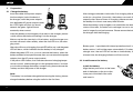
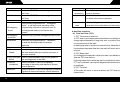
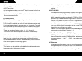
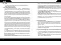
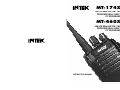
MT-174XPS
136-174 MHz VHF FM / 16CH / 5W
PROFESSIONAL 2-WAY RADIO
PC PROGRAMMABLE
MT-460XPS
420-470 MHz UHF FM / 16CH / 4W
PROFESSIONAL 2-WAY RADIO
PC PROGRAMMABLE
INSTRUCTION MANUAL
User Information
USER INFORMATION
in accordance with art. 13 of the Legislative Decree of 25th July 2005, no. 15
”Implementation of Directives 2002/95/EC, 2002/96/EC and 2003/108/EC, relative
to reduction of the use of hazardous substances in electrical and electronic equipment, in addition to waste disposal”.
The crossed bin symbol shown on the equipment indicates that at the
end of its working life the product must be collected separately from
other waste.
The user must therefore take the above equipment to the appropriate
differentiated collection centres for electronic and electro technical
waste, or return it to the dealer when purchasing a new appliance of
equivalent type, in a ratio of one to one.
Appropriate differentiated waste collection for subsequent recycling, treatment and
environment-friendly disposal of the discarded equipment helps to prevent possible
negative environmental and health effects and encourages recycling of the component materials of the equipment.
Illegal disposal of the product by the user will be punished by application of the
administrative fines provided for by the legislative decree no. 22/1997 (article 50
and following of the legislative decree no. 22/1997).
INSTRUCTION MANUAL
FM HANDHELD TRANSCEIVER
We are very grateful for your purchasing
brand two-
way radios produced by
.
We believe
two-way radio, which always incorporates
the latest technology, can bring great convenience to your life
and work;
We also believe that the quality and function of
two-
way radio can meet your demands for reliable communication.
PRECAUTIONS
Please observe the following precautions to prevent fire,
personal injury, and radio damage.
Do not operate your radio while taking on fuel, or being
charged.
Do not expose the radio for a long period to direct sunlight,
nor place the radio close to heating appliances.
20
NOTICE !
It is recommended to carefully read this owner’s manual before using the
product. This will also help the user to prevent using the radio in violation
of the regulations valid in the country where the product is used, as well as
to avoid any possible interferences with other services.
Do not place the radio in excessively dusty areas, humid
areas or on unstable surfaces.
Do not modify this radio for any reason.
Refer service to qualified licensed or certificated technicians
only.
NOTICE !
This transceiver has been factory pre-programmed, in order for the
user to test it right after purchase. It is the user' s responsibility to reprogram the radio, in accordance with the specifications for the frequency channels assigned by the local authority.
NOTICE !
This transceiver is programmable via PC, using the dedicated software
and the PC interface cable (optional items). Any programming or modification of the original default setting must be made by a specialised technician or by an authorised service centre. Some functions of this transceiver might be programmed in violation of the technical rules in force
for the use of the VHF and UHF FM bands. It is the user’s responsibility
to check that any modification to the programming will be done in compliance with the current regulations. Any modification to the product, alteration of the internal circuit, of the external structure of the radio or any
programming in violation of the current regulations will automatically void
the product certification and your right to use the product. INTEK S.R.L.
declines any responsibility concerning any modification of the product,
made by the user or by a third party, after delivery of the product.
Notice to the User:
·
Government laws prohibit radio communication without
permission in government districts.
· Illegal operation is subject to punishment by fine and/or
imprisonment.
· Refer service to the well-trained professional technicians only.
Safety
It is important that the user is aware of and understands hazards
common to the operation of any radios.
Warning !
Your INTEK radio generates RF electromagnetic energy during
transmit mode. This radio is designed for and classified as “ Occupational Use Only” , meaning it must be used only during the
course of employment by individuals aware of the hazards, and
the ways to minimize such hazards. This radio is NOT intended
for use by the “ General Population” in an uncontrolled
environment.
This radio has been tested and complies with the FCC RF expo-
sure limits for “ Occupational Use Only” . In addition, your
authorized by the manufacturer for use with this radio.
INTEK radio complies with the following Standards and
DO NOT transmits for more than 50% of total radio use time (“ 50%
Guidelines with regard to RF energy and electromagnetic energy
duty cycle” ). Transmitting more than 50% of the time can cause
levels and evaluation of such levels for exposure to humans:
FCC RF exposure compliance requirements to be exceeded. The
FCC OET Bulletin 65 Edition 97-01 Supplement C, Evaluating
radio is transmitting when the “ TX indicator” lights red. You can
Compliance with FCC Guidelines for Human Exposure to Radio
cause the radio to transmit by pressing the “ PTT” switch.
Frequency Electromagnetic Fields.
ALWAYS keep the antenna at least 2.5 cm (1 inch) away from the
American National Standards Institute (C95.1-1992), IEEE
body when transmitting and only use the INTEK belt-clip which
Standard for Safety Levels with Respect to Human Exposure to
is listed in instructions when attaching the radio to your belt, etc.,
Radio Frequency Electromagnetic Fields, 3 kHz to 300 GHz.
to ensure FCC RF exposure compliance requirements are not ex-
American National Standards Institute (C95.3-1992), IEEE Re-
ceeded. To provide the recipients of your transmission the best
commended Practice for the Measurement of Potentially Hazar-
sound quality, hold the antenna at least 5 cm (2 inches) from your
dous Electromagnetic Fields RF and Microwave.
mouth, and slightly off to one side.
The following accessories are authorized for use with this product.
The information listed above provides the user with the information
Use of accessories other than those (listed in the instruction)
needed to make him or her aware of RF exposure, and what to
specified may result in RF exposure levels exceeding the FCC
do to as-sure that this radio operates with the FCC RF exposure
requirements for wireless RF exposure.
limits of this radio.
Caution !
your INTEK radio generates RF energy that can possibly cause
Electromagnetic Interference/Compatibility During transmissions,
To ensure that your expose to RF electromagnetic energy is within
interference with other devices or systems. To avoid such interfer-
the FCC allowable limits for occupational use, always adhere to
ence, turn off the radio in areas where signs are posted to do so.
the following guidelines
DO NOT operate the transmitter in areas that are sensitive to ele-
DO NOT operate the radio without a proper antenna attached, as
ctromagnetic radiation such as hospitals, aircraft, and blasting sites.
this may damaged the radio and may also cause you to exceed
Occupational/Controlled Use. Radio transmitter is used in sit-
FCC RF exposure limits. A proper antenna is the antenna supp-
uations in which persons are exposed as consequence of their
lied with this radio by the manufacturer or antenna specifically
employment provided those persons are fully aware of the pote-
ntial for exposure and can exercise control over their exposure.
phone is 5 to 10 cm (2 to 4 inches) away from the lips and the tra-
IMPORTANT
nsceiver is vertical.
READ ALL INSTRUCTIONS carefully and completely before
WARNING !
using the transceiver
NEVER operate the transceiver with a headset or other audio acc-
SAVE THIS INSTRUCTION MANUAL- This instruction manual
essories at high volume levels.
contains important operating instructions for the Two-Way Radio
CAUTION !
EXPLICIT DEFINITIONS
WORD
DEFINITION
the transceiver to a power source other than the Battery listed below
WARNING
NEVER short the terminals of the battery pack. NEVER connect
Personal injury,fire hazard or electric shock
Such a connection will ruin the transceiver.
may occur.
DO NOT push the PTT when not actually desiring to transmit.
CAUTION
Equipment damage may occur.
AVOID using or placing the transceiver in direct sunlight or in areas
NOTE
If disregarded,inconvenience only.No risk
with temperatures below 30
of personal injury,fire or electric shock.
DO NOT modify the transceiver for any reason.
(-22 F) or above +60
(+140 F).
MAKE SURE the flexible antenna and battery pack are securely
OPERATING NOTES
attached to the transceiver, and that the antenna and battery pack
When transmitting with a portable radio, hold the radio in a vertical
are dry before attachment. Exposing the inside of the transceiver to
position with its microphone 5 to 10 cm (2 to 4 inches) away from
water will result in serious damage to the transceiver.
your mouth. Keep the antenna at least 2.5 cm (1 inch) from your
FCC CAUTION: Changes or modifications to this device, not exp-
head and body.
ressly approved by INTEK, could void your authority to operate
If you wear a portable two-way radio on your body, ensure that
this transceiver under FCC regulations.
the antenna is at least 2.5 centimeters (1 inch) from your body
when transmitting.
PRECAUTIONS WARNING !
NEVER hold the transceiver so that the antenna is very close to,
or touching exposed parts of the body, especially the face or eyes,
while transmitting. The transceiver will perform best if the micro-
CONTENTS
1. Package-opened Inspection andInstalling......................................1
2. Preparation......................................................................................2
2.1. Charge the battery..................................................................2
2.2. Install/remove the battery....................................................3-4
2.3. Install the antenna..................................................................4
2.4. Install external speaker/MIC...................................................5
2.5. Install the belt clip....................................................................5
3.Radio Overview................................................................................5
4.Basic Operation................................................................................6
5.Programmable Key Function............................................................7
6.Auxiliary functions.................................................................
.....
...........9
6.1.Time-out Timer.........................................................................9
6.2.Battery saving........................................................................10
6.3.Low battery alarm..................................................................10
6.4.Voice Announcement.............................................................10
6.5. CTCSS / DCS.......................................................................11
6.6.Dual Tone Multi-Frequency (DTMF) coding...........................11
6.7.Talkaround.............................................................................11
6.8.Scan......................................................................................12
6.9.Transmission Begin and Transmission End Signals (PTT ID)...13
6.10.Lone worker / Emergency Alarm.........................................14
7.Wired Clone...................................................................................15
8.Trouble Shooting Guide.................................................................15
9. Specifications / Optional Accessories...........................................17
Declaration of Conformity MT-174XPS.............................................18
Declaration of Conformity MT-460XPS.............................................19
User Information................................................................................20
1. Package-opened Inspection
Please check the host in the package and the supplied accessories
in the following table before using. Any articles are found lost or
damaged, please contact the distributor without delay.
1.1 Supplied Accessories
Accessories
SMA Antenna
Li-Poly Battery Pack
Belt Clip
Desk type quick Charger
AC Adaptor
Hand Strap
User Manual
Quantity
1
1
1
1
1
1
1
SMA Antenna
AC Adaptor
Battery Pack
Desk Charger
Belt Clip
Hand Strap
1
2.
Preparation
2.1 Charge the battery
Insert the cable of the power adaptor
After being purchased or before the first charging after being laid
into the adaptor jack at the back of
aside for a long time (2 months), the battery can reach its normal
the charger, insert the power adaptor
capacity after several times of charging, please ensure to charge
into applicable AC power output socket,
the battery for at least once every three months.
the 1 LED lights will flash for about 1
When the battery is fully charged or not used till the low battery alarm
second, the green light will be on
status of the radio, it's better not to recharge it so as to avoid influe-
constantly when normal.
nce its longevity and performance. Please remove the battery from
Insert the battery to be charged or the radio in the charger, please
the charger after the charging.
switch off the radio before installing it into the charger.
Make sure that the terminals of the battery and the charger can
contact with each other reliably, when the red LED is on, the charging starts.
After about 5 hours of charging, the red LED will be out, and the green
Battery pack is provided with internal protective circuit, in the low
LED will be on, which indicates that the battery is fully charged.
battery status, it will cut the power automatically, if it's charged on the
When the green LED is on, you can remove the battery, when the
charger now, the red LED will not be on immediately, about 1-5
battery reaches its best performance, then you can remove the power
minutes later, the charging indicators will turn normal.
adaptor from the AC power output socket.
If the yellow LED flashes, that indicates abnormal charging tempe-
2.2 Install/remove the battery
rature or circuit, and the charger is in the protected status, in which
you should not charge the battery compulsorily, please remove the
Install the battery
battery and shut the power of the charger.
Align the two protrusions at the lower
end of the battery to the slot at the
Note:
lower part of the shell of the radio
The battery has not been charged when leaving the factory, please
and insert in.
charge the battery before using the radio for the first time.
2
3
2.4 Install external speaker/MIC
Press the upper end of the battery
down till the push button on the radio
completely bounce out and locked.
Open the soft rubber cover of external speaker or MIC with your finger-nail, insert the pin of matching external speaker or MIC into the pinhole
of the radio.
2.5 Install the belt clip
Remove the battery
To remove the battery, slightly
press the battery and pull the push
button upwards, and then remove
the battery from the radio.
Align the guide rail of the support of the
belt clip to the guide slot on the back of the
battery and push downwards properly; to
remove the belt clip, insert your fingernail or a tool into the slot on the
upper part of the belt clip and push the card upward, at the same time,
push the belt clop upward by force to remove it.
3. Radio Overview
Note:
Please avoid short circuit of terminals of the battery or throw
the battery in fire.
Do not remove the shell of the battery by yourself.
2.3 Install the Antenna
Holding the base of the antenna, screw the
antenna clockwise into the connector on top
of the radio till it's fastened.
.LED INDICATOR
Red LED on when transmitting, green LED on when receiving signals.
Red LED flashes when low battery.
.Channel selector knob
4
5
Turning to select channels 1-16.
.Power/Volume knob
. Channel:
Turn the channel selector knob to select
Turn clockwise to turn on the radio, keep turning to adjust the
the required channel. When the correct signal
volume.To turn off the radio, just turn the knob anticlockwise till a
is received, you can hear sounds from the
sound of “ Ka-Da” is produced.
.PTT (PUSH-TO-TALK) key
Press the PTT key and talk towards the MIC to send the voice to the
recipient.
.Side key 1 (programmable key)
.Side key 2 (programmable key)
.Top key (programmable key)
.Speaker/MIC connector
Connecting external speaker and MIC.
speaker.
. Transmission:
To send a call, press the PTT key and speak to
the microphone in the normal voice. Please keep
the microphone about 3 or 4 cm far from your mouth.
. Receive:
The radio will return to the receiving state after
you loosen the PTT key. The distributor may have
set the CTCSS/DCS signaling in the programmed
radio of your radio. On the channels with CTCSS
/DCS are set, you can only hear the call from other
4. Basic Operation
radio with the same CTCSS/DCS.
. Startup:
Turn the Power/Volume knob clockwise to
turn on the radio. If the dealer has set the
5. Programmable Key Function
prompt sound, a sound of “ Bee” will be
Top key, side key 1, side key 2 can be programmed as one of the
produced.
following functions.
Function Description
Keys
. Volume:
0. None
No function
1.Voice
Press this programmable key to switch between
You can press the key programmed to
announcement
different languages and modes of voice announ-
“ cancel squelch” to receive background
selector
-cement and hear the number of channels being
broadcast.
noise and then turn the Power/Volume key
to adjust the volume.
6
2.Talkaround
Switch the radio between talkaround and repeater
7
press again to resume normal operation.
mode.
3.Call Key 1
Sends the DTMF/2Tone code assigned to
4.Call Key 2
Sends the DTMF/2Tone code assigned to
call 1 key.
14.Squelch off
momentary
15.Squelch off
Press the key programmed as “ Emergency
Alarm
Press this key to quit the Emergency Alarm mode.
Alarm Off
8.Mandown
reset
After enabling the Lone worker, press this key to
reset the Lone worker timer and the timing resumes.
6. Auxiliary functions
6.1 Time-out Time (TOT)
1) TOT Transmission time limit:
a) TOT timer is provided to prevent the talker from talking too long and
Press this key programmed for “ Mandown”
occupying the channel for a long time, and to avoid too long continu-
to enter the working mode of mandown
ous transmission of the radio.
(optional)
b) Setting the time for continuous transmission. When the transmiss-
9.Scan
Start/end the scanning function of system.
ion excesses the preset time limit, the radio will alarm and stop trans-
10.Nuisance
Press this key to delete the noise channel when
mission.
the radio enales the scan function and stays at
2) TOT Rekey time:
Delete
the noise channel.
11.Hi-Low Power Press to switch between high and low power of
Switch
12.Monitor
momentary
13.Monitor
8
16.Lone worker
programming software or send your own ID
or background tone to your friend or the
system.
7.Emergency
Hold this key to open the squelch. loosen this key
Enables Lone worker function
Alarm” to set alarm tone according to the
6.Emergency
normal operation.
to return to the normal operation.
call 2 key.
5.Lone worker
Press to enable squelch and release to resume
a) Limiting the time period in which the radio is prohibited to transmit
after the TOT timer actions.
the sending power of the radio.
b) During the period in which the radio is prohibited to transmit, if the
Press to disable CTCSS, DCS signaling
PTT key is pressed, a prompt will be generated and the transmission
according to the setting and release to resume
is prohibited.
normal operation.
3) TOT Pre-Alert
Press to disable CTCSS, DCS signaling to receive
a)The radio will alarm in advance before the TOT timer pauses the
signals that cannot be heart by normal operation.
transmission.
9
b)After the alarm, when the time of transmission exceeds the preset
When changing the channel with the channel selector, after the cha-
time, the TOT timer will act.
nnel is changed, the radio will announce the number of the channel
4) TOT reset time:
selected.
a) Limiting the time delay from the PTT key is loosened to the timer
6.5 CTCSS /DCS
resets.
The dealer may have programmed CTCSS or DCS signals on cha-
b) If the time of releasing the PTT key is shorter than that of the reset,
nnels of the radio, you can ignore calls of other irrespective radios
the countdown continues.
using the same channel.
6.2 battery saving
squelch is only enabled when receiving correct CTCSS or DCS signals.
When a certain channel is provided with CTCSS or DCS signals, the
The dealer may set the energy saving modes of the battery by
Similarly, only radios with the CTCSS/DCS signals con forming to
programming.
that of your radio can receive your signal.
If this function is enabled, the radio will enter the battery saving mode
Note: Although it appears that once you use CTCSS/DCS, you can
If not receiving any signal or any operation for 10 seconds. The radio
have your own channel, if other radios set the same CTCSS or DCS
will automatically quit the battery saving mode if receiving any signal or
operation.
signals, they can still hear your calling.
Remark: if you have higher requirement on the decoding time, please
There are 4 modes of battery saving: 1:1, 1:2, 1:4 and off.
set the power saving mode to "close" or "1:1".
This function can reduce the power consumption of the battery.
6.6 Dual Tone Multi-Frequency (DTMF) Coding
6.3 Low battery alarm
DTMF signaling can be set into code sequence by the dealer, when
In the low battery status, the indicator will flash for prompt. If the battery
the coding template contains DTMF signaling, press corresponding
level is so low as to reach the preset value during transmission of
programmable keys “ Call 1” “ Call2” , the codes can be
signals, the red indicator will flash. When the battery level is too low, the
transmitted.
radio is not capable of transmitting signals.
6.4 Voice announcement
This feature can be enabled or disabled by the dealer and has two
language modes: Chinese and English.
10
6.7 Talkaround
In the communication network, you can expand communication range
through the repeater, but when the radio is out of the communication
range, you can connect with other radio in the talkaround method.
Switch the talkaround or repeater mode through “ Talkaround” key.
11
6.8 Scan
The radio can be programmed to scan multiple channels to
receive signals from them.
6.8.1 Start/End Scan Function
status, it will transmit signals from the current channel, otherwise,
it will transmit signals from the channel where the scan is started.
Priority channel: The priority channel preset in the Scan list.
Priority channel+ current channel: if the radio is at the Scan Staying
a) Press the key programmed to “ Scan” , the Scan function is
status, it will transmit signals from the current channel, otherwise,
entered. During the scan, channels in the scan list of the radio
it will transmit signals from the priority channel.
will stop when signals are found, the radio will stay at the channel
Last calling receiving channel: The channel where the radio has
with signals till the signals disappear, if the time delay between the
received signals for the last time.
signals disappear and the scan resumes, the radio will stay at the
Last transmission + Current channel: if the radio is at the Scan
current channel if no signal is received during the dime delay.
Staying status, it will transmit signals from the current channel,
b) Priority Scan:
otherwise, it will transmit signals from the channel where it has
You can select one channel in the scan list as the priority channel,
transmitted signals for the last time.
which has the highest priority during the scan, during the scan, a
non-priority channel in the scan list will be scanned first, and then
the priority channel, and then the next non-priority channel, and
then the priority channel again, and the scan goes on in this cycle.
If the priority channel and the lookback period are set in the Scan list,
when the radio receives signals in a non-priority channel, it is in
the Scan Stopped status and will lookback the priority channel in a
certain cycle, if there are signals in the priority channel, it will stay
6.8.2 Nuisance Delete
If a channel continuously generates noise or interference, press the
key to remove this channel from the scan list temporarily.
Note: the priority channel can't be removed and the last one in the
scan list, either.
Quit the Scan mode and enter it again, the deleted channel will be
added to the scan list again.
at the priority channel, if there are no, it will return to the original
channel.
c) There are the following options for the revert channel during the
scan set by the dealer (i.e., the transmitting channel during the scan):
Select channel: The radio transmits signals from the channel
where the scan is started.
Select channel + current channel: if the radio is at the Scan Staying
12
6.9 Transmission Begin and Transmission End Signals (PTT ID)
Transmission Begin and transmission End identification signals are
used for continuing with or stopping certain repeaters and phone
systems.
If Transmission Begin has been set, when you press the PTT switch,
the ID signals will be transmitted.
13
If Transmission End has been set, when you release the PTT switch,
7. Wired Clone Mode
the ID signals will be transmitted.
If the wired clone function is enabled, the radio will not quit after
If both have been set, the ID signals will be transmitted respectively
entering the wired clone mode. To return to normal user mode, the
user needs to restart the machine.
when you press and release the PTT switch.
The operating steps go as follows:
1. Press side key 1 for power-on at least 2 seconds and enter the clone
6.10 Lone worker
mode. If the function is disabled, it will enter the user mode.
If Lone worker is set to be enabled, press the key “ Lone worker” to
2. Connect the slave radio with the wired clone cable first, and then
enable the Lone Worker Mode. Start the Lone worker timer and when
turn on.
the preset Lone worker time is reached, the radio will alarm, after the
3. Press side key 2 on the master radio for starting clone. During
alarm time, the radio will enter the Emergency Alarm Mode and give
out the Emergency Alarm.
transmitting the data, the master radio lightens red, and the slave
In the Lone worker Mode, press the “ Lone worker” key again to quit
radio lightens green . After the slave radio receiving all the data,
the red light on the master radio is off, and the slave radio restarts.
the Lone worker mode.
4. You can keep copying according to step 3 above.
In the Lone worker Mode, press the key programmed for “ Lone worker
reset” (the specific key to select lone worker reset mode) or any key
(any key to select lone worker reset mode), the Lone worker timer will
8. Trouble Shooting Guide
start timing again.
No. Problem
1 Power on Failure
6.11 Emergency Alarm
Press the key programmed for “ Emergency Alarm” (the time of
pressing must be longer than the de-bounce time of the emergency
alarm switch) to enter the Emergency Alarm mode. You can set alarm
tone according to the programming software or send your own ID or
background tone to your friend or the system.
In the Emergency Alarm Mode, press the key“ Emergency Alarm Off”
to quit the Emergency Alarm Mode and disable the alarm tone or stop
sending it and resume normal operation.
14
2
Solution
A. Unreliable connection between the battery
and the radio, please reinstall the batter.
B. The protective tube of power is burnt out.
Please change it.
C. Power switch in failure, please change it.
D. The rechargeable battery is out of power.
Please recharge or change a new one.
E. CPU is broken, Please change the IC.
A. Channel frequency beyond the range,
Phase lock loop
unlocked (Beeping) reset channel data.
15
3
4
5
6
16
B. The crystal X4 of phase lock loop is
broken. Please change it.
C. The oscillator transistor is broken.
Please change it.
D. The IC1 of phase lock loop is broken.
Please change IC.
A. The frequency is not right. Please
No talkback
reselect the channel of the same frequency.
B. The CTCSS/DCS code is not the same.
Please reset it.
C. It is out of the effective communication
range.
A. The antenna is not in good contact.
No receiving signal
Please fasten the antenna head.
B. The high-frequency amplifier Q20 is
broken. Please change it.
C. The squelch level is set to high, Please
reset the squelch level.
D. The mixed transistor Q19 is broken.
Please change it.
E. The IC5 is broken. Please change IC.
The red transmission A. Power module Q11 damaged, no power
Indicator lights but no output, please change the module.
B. MIC damaged, please change it.
sound is heard.
A.
The speaker is broken. Please
The green receiving
change
it.
indicator lights but no
B.
The
audio
power amplifier Ic8 is broken.
sound is heard.
Please change IC.
9. SPECIFICATIONS
Frequency (MHz)
Channel spacing
RF power
Channels
Operating Temperature
Power supply
Dimensions
Weight
VHF 136-174 MHz (MT-174XPS)
UHF 420-470 MHz (MT-460XPS)
12.5 / 25 KHz
5W / 1W (MT-174XPS)
4W / 1W (MT-460 XPS)
16 (15+S)
-25°C - +55°C
DC 7.4V
mm 119 (H) x 54.5 (L) x 34 (D) (main body)
247 gr. (with battery pack and antenna)
OPTIONAL ACCESSORIES
KB-70B
KB-70D
KB-2306B
KST-301M
KME-614M
KME-801M
KME-315M
KSPL-09
Li-Poly Battery Pack 7.4V 1700mAh
Car Battery Adaptor with cigarette lighter plug
Multiple Desk Charger
External "Heavy Duty" speaker-microphone
External earset-microphone with adjustable ear hook
External earset-microphone for security and bodyguard
External earset-microphone with special soft tear proof cable
PC interface USB cable
17
Declaration of Conformity MT-174XPS
Declaration of Conformity MT-460XPS
EC Certificate of Conformity
EC Certificate of Conformity
(to EC Directive 2006/95, 2004/108, 99/5)
(to EC Directive 2006/95, 2004/108, 99/5)
DECLARATION OF CONFORMITY
DECLARATION OF CONFORMITY
With the present declaration, we certify that the following products :
With the present declaration, we certify that the following products :
INTEK MT-174XPS
INTEK MT-460XPS
comply with all the technical regulations applicable to the above mentioned products
in accordance with the EC Directives 2006/95/EC, 2004/108/EC, 99/5/EC.
comply with all the technical regulations applicable to the above mentioned products
in accordance with the EC Directives 2006/95/EC, 2004/108/EC, 99/5/EC.
Type of product :
VHF PMR Transceiver
Type of product :
UHF PMR Transceiver
Details of applied standards :
EN 300 086 -1/-2, EN 301 489-1-5
Details of applied standards :
EN 300 086 -1/-2, EN 301 489-1-5
EN 60950-1
EN 60950-1
Manufacturer :
INTEK S.R.L.
Via G. Marconi, 16
20090 Segrate, Italy
Tel. 39-02-26950451 / Fax. 39-02-26952185
E-mail : [email protected]
Manufacturer :
INTEK S.R.L.
Via G. Marconi, 16
20090 Segrate, Italy
Tel. 39-02-26950451 / Fax. 39-02-26952185
E-mail : [email protected]
Notified Body :
EMCCert Dr. Rasek
Boelwiese 5, 91320 Ebermannstadt
Germany
Identification Number : 0678
Notified Body :
EMCCert Dr. Rasek
Boelwiese 5, 91320 Ebermannstadt
Germany
Identification Number : 0678
Contact Reference :
Armando Zanni
Tel. 39-02-26950451 / Fax. 39-02-26952185
E-mail : [email protected]
Contact Reference :
Armando Zanni
Tel. 39-02-26950451 / Fax. 39-02-26952185
E-mail : [email protected]
dr. Vittorio Zanetti
Segrate, 13/01/2012
Segrate, 12/01/2012
(General Manager)
0678
18
dr. Vittorio Zanetti
(General Manager)
RoHS
2002/95/EC
19