1
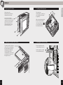
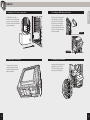
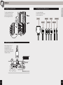
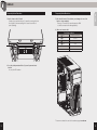
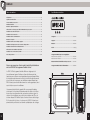
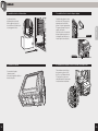
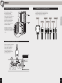
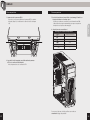
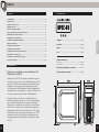
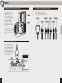
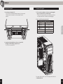
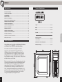
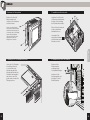
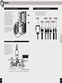
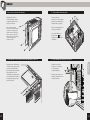
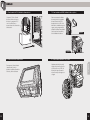
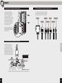
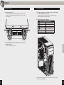
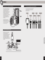
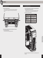
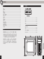
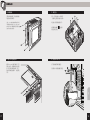
CARBIDE SERIES® SPEC-03 MID-TOWER GAMING CASE INSTALLATION GUIDE / GUIDE D'INSTALLATION INSTALLATIONSHANDBUCH / GUIDA DI INSTALLAZIONE GUÍA DE INSTALACIÓN / РУКОВОДСТВО ПО УСТАНОВКЕ / Ꭷፑೌ / ͼϋΑΠȜσ΄ͼΡ English:..................................................................................................................... 1-12 Français:.................................................................................................................13-24 Italiano:...................................................................................................................21-30 Deutsch:.................................................................................................................31-40 Español:..................................................................................................................41-50 Россию:....................................................................................................................51-60 中文:..........................................................................................................................61-70 日本語:......................................................................................................................71-80 SPEC-03 Table of Contents Case Specifications ENGLISH Congratulations:...........................................................................................................................................................1 Case specifications:....................................................................................................................................................2 Accessory kit contents:.............................................................................................................................................3 Case features:................................................................................................................................................................4 Removing the side panels:.......................................................................................................................................5 Utilizing the CPU power cable cut-out:..............................................................................................................5 Installing the motherboard:.....................................................................................................................................6 Installing the PCI-E/PCI card(s):...........................................................................................................................6 Installing the PSU:........................................................................................................................................................7 Removing the front fascia:.......................................................................................................................................7 Installing an ODD:........................................................................................................................................................8 Length:....................................................................................................... 493mm Width:........................................................................................................ 215mm Installing SSDs and HDDs:........................................................................................................................................8 Height:....................................................................................................... 426mm Installing a second front fan:..................................................................................................................................9 Weight:........................................................................................................5.65kg Powering the case fans:.............................................................................................................................................9 Installing the front I/O connectors:...................................................................................................................10 Frequently asked questions:..........................................................................................................................11-12 Congratulations! Maximum GPU length: Top slots:................................................................................................... 420mm Lower slots:.............................................................................................. 270mm Maximum CPU cooler height:.......................................................... 157mm Thank you for purchasing a Carbide Series® SPEC-03 Mid-Tower Case. Maximum PSU length:......................................................................... 288mm The SPEC-03 features an industrial, high-airflow front panel, a huge windowed side panel and a front 120mm LED fan. Add to that our USB 3.0 and native, tool-free SSD and HDD installation and you can have your killer gaming rig up and running in minutes. Most cases at this price point don’t give you the combination of great looks and great features that the SPEC-03 does. Up to dual 140mm front intake fan, an rear 120mm exhaust, and room for massive graphics cards makes the SPEC-03 stand out among the crowd. 1 2 SPEC-03 Accessory Kit Contents x4 b x10 MBD/HDD screws Cable ties c x16 SSD/ODD screws A I/O panel (x2 USB 3.0, Headphone/Mic, and Power/Reset) B Removable front fascia C Front 120mm LED intake fan with x2 140mm fan compatibility D Rear 120mm exhaust fan E x2 Top 120mm fan mounts F Windowed side panel G x3 5.25" Tool-free drive bays H Bottom PSU mount and dust filter I Front dust filter and mesh cover J x2 Tool-free 2.5" drive mounts K Top dust filter with pins L x2 Tool-free removable ODD covers M CPU backplate cutout M d x4 Short fan screws SSD pan h ead screws g e x16 f ENGLISH a Case Features L x4 Long fan screws x1 Motherboard standoffs 3 4 SPEC-03 carbide spec-03 STEP 01 carbide spec-03 STEP 03 / ps 3. Installing the Motherboard Simply remove the thumbscrews then slide the side panels back and out. First, install your motherboard’s I/O shield (see your motherboard’s manual for guidance). Note: Corsair recommends removing both side panels and setting them aside when building your system to avoid accidental damage. Both side panels are interchangeable and should be removed to reduce clutter. carbide spec-02 STEP 02 2. Utilizing the CPU power cable cut-out To install your flat CPU 8/4 pin cable, route the cable through the motherboard tray before installing the motherboard. Only Flat Cables will be compatible and you must split your cable into 2 pieces to fit through the cutout. ENGLISH 1. Removing the Side Panels lign your motherboard with A the pre-installed standoffs. Use the provided screws b to secure the motherboard to the motherboard tray. 4. Installing the PCI-E/PCI card(s) emove thumbscrews and R corresponding slot cover(s). 1 Install the add-on card and secure with thumbscrews. 2 5 6 SPEC-03 5. Installing the PSU (Power Supply Unit) 03 c e p s e d i carb 05 STEP 6. Removing the Front Fascia To remove the front fascia (front panel),grasp the tab located at the bottom fascia and pull outward. 7 ENGLISH Position the PSU on the bottom of the case then align the caseholes and secure the PSU with screws provided with your power supply. carbide spec-03 carbide spec-03 STEP 06 / sl STEPDisk 06 / sl 7. Installing an ODD (Optical Drive) First, remove the front panel 5.25" drive bay cover then slide the ODD into the drive bay until the tool-free latch clicks, securing the drive. To release an optical drive, push in the tool-free tab then pull the drive outward. First carbide spec-02 STEP 08 Second carbide spec-02 8. Installing SSDs and HDDs STEP 08 Simply pull back retention arm and slide in the 2.5" SSD or 3.5" HDD until the retention arm snaps back into place. 8 SPEC-03 carbide spec-02 STEP 08 To install an additional 120mm or 140mm fan, unscrew the top fan then slide it down to the mounting points below. 11. Installing the Front I/O Connectors ENGLISH carbide spec-02 9. Installing a Second Front Fan STEP 08 See your motherboard’s manual for front panel header locations and pin-outs. POWER SW USB 3.0 HD AUDIO HDD LED RESET SW POWER LED – POWER LED + 10. Powering the Case Fans After locating your 3 or 4 pin fan headers on your motherboard(see your motherboard’s manual for fan header locations), plug in the included fan cable. 9 10 SPEC-03 Frequently Asked Questions 1. How do I remove the I/O Panel? If needed, you can uninstall your I/O panel by removing the front fascia (step 6) then unscrewing the 2 screws at each side of panel. (drawing) 3. W ho should I contact if I received my case damaged or one of the fans is no longer working? Please go to corsair.force.com and request an RMA so that we can replace the damaged part(s). ENGLISH Frequently Asked Questions 4. Where can I mount a fan? Fan Mount Locations 1 Front 2 Top x2 120mm or x2 140mm x2 120mm 3 Rear 120mm 4 Bottom 120mm Side x Mid x 2 2. D oes the polarity matter with the I/O panel’s power and reset header? No, only the LED headers. 3 1 4 To learn more about this case visit the product page at corsair.com 11 12 SPEC-03 Table des matières Spécifications du boîtier Félicitations:.................................................................................................................................................................13 Spécifications du boîtier:........................................................................................................................................14 Contenu du kit d’accessoires:...............................................................................................................................15 FRANÇAIS Attributs du boîtier:..................................................................................................................................................16 Retrait des panneaux latéraux:............................................................................................................................17 Utilisation de la découpe pour câble d’alimentation du processeur:..................................................17 Installation des cartes PCI-E/PCI:.......................................................................................................................18 Installation de la carte mère:................................................................................................................................18 Installation du bloc d’alimentation:...................................................................................................................19 Retrait de la façade:..................................................................................................................................................19 Installation d’un lecteur de disque optique:..................................................................................................20 Longueur:................................................................................................. 493mm Largeur:..................................................................................................... 215mm Installation de disques SSD et de lecteurs de disques durs:...................................................................20 Hauteur:..................................................................................................... 426mm Installation d’un deuxième ventilateur avant:...............................................................................................21 Poids:............................................................................................................5.65kg Alimentation des ventilateurs du boîtier:........................................................................................................21 Installation des connecteurs E/S avant:...........................................................................................................22 Foire aux questions:...........................................................................................................................................23-24 Félicitations ! Longueur maximale du processeur graphique: Emplacements supérieurs:................................................................. 420mm Emplacements inférieurs:................................................................... 270mm Hauteur maximale du refroidisseur de processeur:............... 157mm Nous vous remercions d’avoir acheté un boîtier d’ordinateur mi-tour SPEC-03 de la gamme Carbide Series®. Longueur maximale du bloc d’alimentation:............................ 288mm Le SPEC-023 de la gamme Carbide affiche un design spécial jeu extrêmement agressif et dispose d’un refroidissement à air supérieur pour votre processeur graphique hyper-performant. Grâce à un intérieur astucieusement conçu, le potentiel de refroidissement de ce boîtier est énorme avec un ventilateur aspirant illuminé par DEL à l’avant, pour refroidir directement vos cartes graphiques, ainsi que de la place pour six ventilateurs. Un panneau latéral vitré de grande taille vous permet d’admirer votre travail, et le système d’acheminement des câbles et les filtres à poussières vous permettent de construire un système soigné et ordonné. Une installation sans outil de trois disques durs 3,5 po et de deux disques SSD facilite l’ajout et la mise à niveau du stockage. Et, il est aussi facile à vivre -- les deux ports USB 3.0 à l’avant vous permettent de profiter des tout derniers périphériques de stockage. 13 14 SPEC-03 Contenu du kit d’accessoires x4 attache-câbles b x10 vis pour MBD/HDD c A Panneau E/S (x2 USB 3.0, Casque/Mic, et Alimentation/Réinitialisation) B Façade amovible C Ventilateur aspirant DEL de 120 mm à l’avant et compatibilité avec 2 ventilateurs de 140 mm D Ventilateur d’évacuation de 120 mm à l’arrière E x2 fixations supérieures pour ventilateur de 120 mm F Panneau latéral à fenêtre G 3 baies pour disque de 3,5 po - sans outil H Montage en bas du bloc d’alimentation et filtre à poussière I Filtre à poussière à l’avant et maillage J 2 supports pour disque de 2,5 po - sans outil K Filtre à poussière au-dessus avec broches L x2 caches pour lecteurs optiques amovibles sans outils M Découpage dans la plaque arrière du processeur x16 vis pour SSD/ Disque optique M d x4 vis à tête cylindrique bombée pour SSD g e vis courtes pour ventilateur x16 f FRANÇAIS a Attributs du boîtier L x4 vis longues pour ventilateur x1 entretoise pour carte mère 15 16 SPEC-03 carbide spec-03 STEP 01 carbide spec-03 STEP 03 / ps 3. Installation de la carte mère Retirez simplement les vis de serrage et faites glisser les panneaux latéraux vers l’arrière pour les sortir. Tout d’abord, installez le blindage d’E/S de la carte mère (reportez-vous au manuel d’instructions de la carte mère). Remarque : Corsair recommande de retirer les deux panneaux latéraux et de les mettre de côté lors de la construction de votre système, afin d’éviter tout endommagement accidentel. Il est recommandé d’enlever ces deux panneaux interchangeables pour créer plus de place. carbide spec-02 STEP 02 2. Utilisation de la découpe pour câble d’alimentation du processeur Pour installer le câble plat à broches 8/4 du processeur, passez-le à travers le plateau de la carte mère avant d’installer cette dernière. Seuls les câbles plats sont compatibles et vous devez séparer le câble en deux pour qu’il rentre dans l’espace. FRANÇAIS 1. Retrait des panneaux latéraux lignez la carte mère A avec les entretoises préinstallées. Servez-vous des vis fournies b pour fixer la carte mère au plateau. 4. Installation des cartes PCI-E/PCI etirez les vis de serrage et R le(s) cache(s) d’emplacement correspondant(s). 1 Installez la carte complémentaire et fixez-la avec les vis. 2 17 18 SPEC-03 5. Installation du bloc d’alimentation 03 c e p s e d i carb 05 STEP 6. Retrait de la façade Pour retirer la façade (panneau avant), tirez sur la languette située en bas de la façade. 19 Tout d’abord, retirez le cache de la baie de 5,25 pouces du panneau avant, puis faites glisser le lecteur optique dans le logement jusqu’à ce que le loquet s’enclenche. Pour faire sortir un lecteur de disque optique, appuyez sur la languette, puis tirez sur le lecteur (pas besoin d’outils). Première FRANÇAIS Positionnez le bloc d’alimentation en bas du boîtier, alignez-le avec les trouset fixez-le à l’aide des vis accompagnant le bloc. carbide spec-03 carbide spec-03 STEP 06 / sl STEP 06 optique / sl 7. Installation d’un lecteur de disque carbide spec-02 STEP 08 Deuxième carbide spec-02 8. Installation disques SSD et de lecteurs de disques durs STEPde08 Tirez simplement sur le bras de retenue et glissez le SSD de 2,5 po ou le disque dur de 3,5 po jusqu’à ce que vous entendiez un déclic annonçant le réenclenchement du bras. 20 SPEC-03 carbide spec-02 STEP 08 carbide spec-02 STEP 08 11. Installation des connecteurs E/S avant Pour installer un ventilateur de 120 mm ou 140 mm complémentaire, retirez la façade (étape 5), puis dévissez le ventilateur supérieur et descendez-le au niveau des points de montage inférieurs. Ensuite, servez-vous des longues vis (f) pour poser le nouveau ventilateur. Consultez le manuel de la carte mère pour plus d’informations sur l’emplacement des cavaliers et des broches de sortie. POWER SW USB 3.0 HD AUDIO HDD LED RESET SW POWER LED – POWER LED + FRANÇAIS 9. Installation d’un deuxième ventilateur avant Remarque : pour maximiser le débit d’air, vous pouvez installer deux ventilateurs soit de 120 mm, soit de 140 mm sur le devant du châssis. 10. Alimentation des ventilateurs du boîtier Après avoir repéré les cavaliers à 3 ou 4 broches situés sur la carte mère (consultez le manuel de la carte mère pour l’emplacement des cavaliers), branchez le câble de ventilateur fourni. 21 22 SPEC-03 Foire aux questions 1. Comment retirer le panneau d’E/S ? S i besoin est, vous pouvez démonter le panneau d’E/S en retirant la façade (étape 6) et en dévissant les deux vis situées de chaque côté. 3. À qui dois-je m’adresser si mon boîtier est endommagé à l’arrivée ou lorsqu’un ventilateur ne fonctionne plus ? Veuillez vous rendre sur corsair.force.com et demandez un RMA (Autorisation de retour de marchandise) pour que nous puissions remplacer la ou les pièces endommagées. 4. Où puis-je monter un ventilateur ? Montage pour ventilateur Emplacements 1 Avant x2 120mm or x2 140mm 2 Haut x2 120mm 3 Arrière 120mm 4 Bas 120mm Côté x Milieu x FRANÇAIS Foire aux questions 2 2. L a polarité est-elle importante avec l’alimentation du panneau d’E/S et le cavalier de réinitialisation ? Non, uniquement avec les cavaliers de DEL. 3 1 4 Pour en savoir plus sur ce boîtier, veuillez vous rendre sur corsair.com à la page des produits. 23 24 SPEC-03 Sommario Specifiche case Congratulazioni:.........................................................................................................................................................25 Specifiche case:..........................................................................................................................................................26 Contenuto kit di accessori:....................................................................................................................................27 Caratteristiche case:.................................................................................................................................................28 Rimozione dei pannelli laterali:...........................................................................................................................29 Impiego dell’intaglio cavi di alimentazione CPU:........................................................................................29 Installazione delle schede PCI-E/PCI:..............................................................................................................30 Installazione della scheda madre:......................................................................................................................30 Installazione dell’unità di alimentazione:........................................................................................................31 Installazione di un’unità ODD:..............................................................................................................................32 Lunghezza:............................................................................................... 493mm Profondità:............................................................................................... 215mm Installazione unità SSD e HDD:............................................................................................................................32 Altezza:...................................................................................................... 426mm Installazione di una seconda ventola frontale:..............................................................................................33 Peso:.............................................................................................................5.65kg ITALIANO Rimozione del frontale:...........................................................................................................................................31 Alimentazione ventole del case:.........................................................................................................................33 Installazione dei connettori di I/O frontali:....................................................................................................34 Domande più frequenti:...................................................................................................................................35-36 Congratulazioni! Lunghezza massima GPU: Slot superiori:.......................................................................................... 420mm Slot inferiori:............................................................................................. 270mm Altezza massima raffreddatore CPU: 150mm:......................... 157mm Grazie per aver acquistato un case mid-tower per PC Carbide Series® SPEC-03 Lunghezza massima PSU: 230mm:................................................ 288mm Carbide Series SPEC-03 ha un design estremamente grintoso ed orientato al gioco ed un sistema di raffreddamento di livello superiore per le GPU ad alte prestazioni. Gli interni dal design intelligente consentono alla ventola d’aspirazione frontale con illuminazione a LED di indirizzare l’aria di raffreddamento direttamente sulle schede grafiche e c’è spazio sufficiente fino a sei ventole per il massimo potenziale di raffreddamento. Il pannello laterale è provvisto di un’ampia finestra che ti permette di ammirare il tuo lavoro, e il sistema di istradamento dei cavi insieme ai filtri antipolvere ti aiutano a mantenere il sistema pulito. L’installazione senza viti fino a tre dischi rigidi da 3,5 pollici e due unità a stato solido facilitano l’aggiunta e l’aggiornamento della memoria di archiviazione. E non manca di renderti la vita più sempre, grazie alle doppie porte USB 3.0 sul pannello frontale che ti permettono di trarre il massimo vantaggio dagli ultimissimi dispositivi di archiviazione ad alta velocità. 25 26 SPEC-03 Contenuto kit di accessori Caratteristiche case A Pannello I/O (2 prese USB 3.0, cuffie/microfono, alimentazione/Reset) B Frontale rimovibile C x4 fascette per cavi b x10 viti per scheda madre/unità HDD c D Ventola di scarico posteriore da 120 mm E 2 punti di montaggio superiore per ventole da 120mm F Pannello laterale con finestra G 3 Alloggiamenti unità da 5,25 pollici senza viti H Supporto inferiore per PSU e filtro antipolvere I Filtro antipolvere e copertura a rete frontali J 2 supporti per unità da 2,5 pollici senza viti K Filtro antipolvere superiore con pin L 2 coperture per unità ODD rimovibili M Piastra posteriore con intaglio della CPU x16 viti per unità SSD/ ODD M d x4 viti a testa piatta per unità SSD g e x16 f ITALIANO a Ventola d’aspirazione frontale da 120 mm con LED e compatibilità con 2 ventole da 140mm L x4 viti lunghe per ventola x1 distanziatore per la scheda madre 27 28 SPEC-03 carbide spec-03 STEP 01 carbide spec-03 STEP 03 / ps 1. Rimozione dei pannelli laterali 3. Installazione della scheda madre Rimuovere semplicemente le viti e fare scorrere il pannello laterale all’indietro e verso l’esterno. Prima di tutto, installare l’I/O shield della scheda madre. Per istruzioni, vedere il manuale della scheda madre. Nota: Corsair consiglia di rimuovere e mettere da parte entrambi i pannelli per evitare danni accidentali durante l’assemblaggio del sistema. Entrambi i pannelli laterali sono intercambiabili e dovrebbero essere rimossi per ridurre l’ingombro. llineare la scheda madre ai A distanziatori preinstallati. Per installare il cavo piatto a 8/4 pin per CPU, instradare i cavi attraverso il vano della scheda madre prima di installarla. Solo i cavi piatti sono compatibili ed è necessario dividere il cavo in due metà per poter entrare nel relativo intaglio. ITALIANO carbide spec-02 STEP 02 2. Impiego dell’intaglio cavi di alimentazione CPU Utilizzare le viti in dotazione b per fissare la scheda madre al vano corrispondente. 4. Installazione delle schede PCI-E/PCI Rimuovere le viti e le coperture degli slot corrispondenti. 1 Installare la scheda addon e fissare con le viti a testa piatta. 2 29 30 SPEC-03 5. Installazione dell’unità di alimentazione (PSU) Posizionare la PSU sul fondo del case, quindi allinearla con i fori del case e fissarla con le viti in dotazione all’unità di alimentazione. 6. Rimozione del frontale Per rimuovere il frontale (pannello frontale), afferrare la linguetta posizionata in basso e tirare verso l’esterno. 31 Prima di tutto, rimuovere il coperchio dell’alloggiamento per unità da 5,25 pollici nel pannello frontale, quindi inserire l’unità ODD nel vano fino a far scattare i fermi di fissaggio dell’unità senza viti. Per rimuovere un’unità ottica, premere la linguetta di rilascio senza viti e tirare l’unità verso l’esterno. Primo carbide spec-02 STEP 08 ITALIANO 03 c e p s e d i carb 05 STEP carbide spec-03 carbide spec-03 STEP 06 / sl STEP / sl 7. Installazione di un’unità ODD 06 (Optical Disk Drive) Secondo carbide spec-02 8. Installazione STEP unità 08SSD e HDD Tirare indietro la staffa di bloccaggio ed inserire l’unità SSD da 2,5 pollici o l’unità HDD da 3,5 pollici fino a quando la staffa di bloccaggio non torna in posizione. 32 SPEC-03 carbide spec-02 STEP 08 carbide spec-02 STEP 08 9. Installazione di una seconda ventola frontale 11. Installazione dei connettori di I/O frontali Per installare una ventola aggiuntiva da 120 mm o 140 mm, rimuovere il frontale (fase 5) e svitare la ventola superiore, quindi farla scivolare verso il basso in direzione dei punti di montaggio. Successivamente, utilizzare le viti lunghe per ventola in dotazione (f) per montare la nuova ventola. Per i piedini in uscita e la posizione dei connettori del pannello frontale, consultare il manuale per la scheda madre. HD AUDIO HDD LED RESET SW POWER LED – POWER LED + ITALIANO Nota: Per massimizzare il flusso d’aria, è possibile installare sia 2 ventole da 120mm che 2 ventole da 140mm nella parte frontale del telaio POWER SW USB 3.0 10. Alimentazione ventole del case Dopo il posizionamento dei connettori della ventola a 3 o 4 pin sulla scheda madre (per istruzioni sul posizionamento dei connettori della ventola, vedere il manuale della scheda madre), collegare il cavo della ventola in dotazione. 33 34 SPEC-03 Domande più frequenti Domande più frequenti 1. Come rimuovere il pannello I/O? S e necessario, è possibile disinstallare il pannello I/O rimuovendo il frontale (fase 6) e svitando le 2 viti su entrambi i lati del pannello. 3. C hi è necessario contattare se si riceve un case danneggiato oppure se una delle ventole non funziona più? Visitare il sito www.corsair.force.com e richiedere un RMA in modo da permetterci di sostituire le parti danneggiate. 4. Dopo è possibile montare una ventola? Posizioni di montaggio delle ventole Anteriore x2 120mm or x2 140mm 2 Superiore x2 120mm 3 Posteriore 120mm 4 Inferiore 120mm Laterale x Al centro x ITALIANO 1 2 2. L a questione delle polarità ha a che fare con i connettori di resettaggio e di alimentazione del pannello I/O? No, solo con i connettori LED. 3 1 4 Per saperne di più su questo case, visita la pagina del prodotto sul sito www.corsair.com 35 36 SPEC-03 Inhaltsverzeichnis Technische Daten Gehäuse Herzlichen Glückwunsch:........................................................................................................................................37 Technische Daten Gehäuse:...................................................................................................................................38 Inhalt Zubehörkit:......................................................................................................................................................39 Merkmale Gehäuse:...................................................................................................................................................40 Entfernen der Seitenplatten:.................................................................................................................................41 Nutzung des CPU-Stromkabelausschnitts:......................................................................................................41 Installation der PCI-E-/PCI-Karte(n):................................................................................................................42 Installation des Motherboards:............................................................................................................................42 Installation des Netzgerätes (PSU):...................................................................................................................43 Entfernen der Frontplatte:.....................................................................................................................................43 Installation eines ODDs:..........................................................................................................................................44 Länge:........................................................................................................ 493mm Breite:......................................................................................................... 215mm Installation von SSDs und HDDs:.........................................................................................................................44 Höhe:.......................................................................................................... 426mm Installation eines zweiten Frontlüfters:............................................................................................................45 Gewicht:......................................................................................................5.65kg Antrieb der Gehäuselüfter:....................................................................................................................................45 Häufig gestellte Fragen:...................................................................................................................................47-48 Herzlichen Glückwunsch! Maximale GPU-Länge: Obere Schächte:..................................................................................... 420mm Untere Schächte:.................................................................................... 270mm DEUTSCH Installation der vorderen I/O-Anschlüsse:......................................................................................................46 Maximale Höhe des CPU-Kühlsystems:....................................... 157mm Vielen Dank, dass Sie sich für ein Mid-Tower-PC-Gehäuse der Carbide Series® SPEC-03 entschieden haben. Maximale GPU-Länge:......................................................................... 288mm Die Carbide Series SPEC-03 verfügt über ein äußerst aggressives, spieleorientiertes Design und überlegene Luftkühlung für Ihre Hochleistungs-Grafikprozessoren. Das clever gestaltete Innere ist so angelegt, dass der integrierte LED-beleuchtete Front-Ansauglüfter kühle Luft direkt über Ihren Grafikkarten ansaugt, und es gibt massives Kühlpotenzial mit Platz für bis zu sechs Lüftern. Es gibt ein riesiges Fenster an der Seitenabdeckung, durch das Sie Ihre Arbeit bewundern können, und Kabelführungssystem und Staubfilter lassen Sie ein sauberes System bauen und sauber halten. Mit bis zu drei 3,5-Zoll Festplatten und zwei SSD-Laufwerken, die werkzeuglos installiert werden, ist es leicht, Speicherplatz hinzuzufügen und zu aktualisieren. Und das Leben mit ihm ist ebenfalls einfach: Durch die beiden USB 3.0 Ports an der Frontabdeckung können Sie die neuesten Hochgeschwindigkeits-Speichergeräte nutzen. 37 38 SPEC-03 Inhalt Zubehörkit a x4 Kabelbinder Merkmale Gehäuse b x10 MBD/HDDSchrauben c x16 SSD/ODD-Schrauben I/O-Abdeckung (2 USB 3.0-Anschlüsse, Kopfhörer/Mikrofon und Stromschalter/Reset) B Abnehmbare Frontplatte C 120 mm LED-Ansauglüfter auf der Vorderseite mit Kompatibilität für zwei 140 mm Lüfter D 120 mm Abluftventilator auf der Rückseite E 2 120 mm Montagepunkte für obere Lüfter F Seitenabdeckung mit Fenster G Drei 5,25 Zoll werkzeuglose Laufwerkschächte H Unten angebrachtes Netzteil und Staubfilter I Front-Staubfilter und Netzgitter J Zwei 2,5 Zoll Laufwerkhalterungen K Oberer Staubfilter mit Stiften L 2 werkzeuglos abnehmbare ODD-Abdeckungen M Öffnung für CPU-Backplate DEUTSCH A M d x4 SSDBecherschrauben g e Kurze Lüfterschrauben x16 f L x4 Lange Lüfterschrauben x1 MotherboardAbstandsbolzen 39 40 SPEC-03 carbide spec-03 STEP 01 carbide spec-03 STEP 03 / ps 1. Entfernen der Seitenplatten 3. Installation des Motherboards Entfernen Sie einfach die Rändelschrauben und schieben Sie die Seitenplatte nach hinten heraus. Installieren Sie als Erstes die I/O-Blende des Motherboards (befolgen Sie die Anleitung des Motherboard-Herstellers). Hinweis: Sie sollten beim Bau Ihres Systems beide Seitenplatten entfernen und beiseite legen, um zu vermeiden, dass sie beschädigt werden. Beide Seitenplatten sind auswechselbar und sollten abgenommen werden, um Kabelgewirr zu vermeiden. Richten Sie das Motherboard an den vorinstallierten Abstandsbolzen aus. Um das 8/4 CPU-Flachkabel zu installieren, führen Sie es vor dem Einbau des Motherboards durch den Motherboard-Einschub. Nur Flachkabel sind kompatibel und müssen in zwei Teile geteilt werden, um durch die Öffnung zu passen. b DEUTSCH carbide spec-02 STEP 02 2. Nutzung des CPU-Stromkabelausschnitts Verwenden Sie die mitgelieferten Schrauben um das Motherboard am Einschub zu sichern. 4. Installation der PCI-E-/PCI-Karte(n) Entfernen Sie die Rändelschrauben und dazugehörige Steckplatzabdeckungen. 1 Installieren Sie die Erweiterungskarte und befestigen Sie sie mit Rändelschrauben. 2 41 42 SPEC-03 5. Installation des Netzgerätes (PSU) Platzieren Sie das Netzgerät auf den Gehäuseboden, richten Sie es an den Gehäuseöffnungen aus und sichern Sie es mit den im Lieferumfang enthaltenen Schrauben. 6. Entfernen der Frontplatte Ziehen Sie zum Entfernen der Frontplatte an ihrer Entriegelungstaste an der Unterseite und ziehen Sie sie heraus. 43 Nehmen Sie als Erstes die Abdeckung des 5,25-ZollLaufwerkschachts auf der Frontplatte ab und schieben Sie das ODD dann in den Laufwerkschacht, bis die Zunge einrastet und das Laufwerk sicher sitzt (werkzeuglose Installation). Ein optisches Laufwerk wird werkzeuglos entfernt. Drücken Sie dazu die Entriegelungstaste und ziehen Sie es nach außen. First carbide spec-02 STEP 08 Second carbide spec-02 8. Installation SSDs und HDDs STEPvon08 DEUTSCH 03 c e p s e d i carb 05 STEP carbide spec-03 carbide spec-03 STEP 06 / sl STEP 06 Laufwerk) / sl 7. Installation eines ODDs (optisches Ziehen Sie einfach den Haltearm zurück und schieben Sie das 2,5-Zoll SSD oder 3,5-Zoll HDD hinein, bis der Haltearm zurück an seinen Platz schnappt. 44 SPEC-03 carbide spec-02 STEP 08 carbide spec-02 STEP 08 9. Installation eines zweiten Frontlüfters 11. Installation der vorderen I/O-Anschlüsse Um einen zusätzlichen 120 mm oder 140 mm Lüfter zu installieren, nehmen Sie die Frontplatte ab (Schritt 5) und lösen Sie den oberen Lüfter. Schieben Sie ihn dann auf die tieferen Montagepunkte. Bringen Sie dann den neuen Lüfter mit den mitgelieferten langen Lüfterschrauben (f) an. Die Position der Frontplatten-Header und die Pinbelegung finden Sie in der Anleitung Ihres Motherboards. POWER SW USB 3.0 HD AUDIO HDD LED RESET SW POWER LED – POWER LED + Hinweis: Um den Luftstrom zu maximieren, können Sie entweder zwei 120 mm oder zwei 140 mm Lüfter in der Gehäusefront installieren. DEUTSCH 10. Antrieb der Gehäuselüfter Stecken Sie das im Lieferumfang enthaltene Lüfterkabel in den 3- oder 4-poligen Lüfteranschluss auf dem Motherboard (die Position der Lüfter-Header finden in der Anleitung Ihres Motherboards). 45 46 SPEC-03 Häufig gestellte Fragen Häufig gestellte Fragen 1. Wie kann ich die I/O-Abdeckung entfernen? W enn nötig, können Sie Ihre I/O-Abdeckung von der Frontplatte abnehmen (Schritt 6) und dann die beiden Schrauben lösen, die sich jeweils an der Seite der Abdeckung befinden. 3. A n wen kann ich mich wenden, wenn ich ein beschädigtes Gehäuse erhalten habe oder einer der Lüfter nicht mehr funktioniert? Bitte besuchen Sie corsair.force.com und fordern Sie eine RMA an, damit wir das/die beschädigte(n) Teil(e) ersetzen können. 4. Wo kann ich einen Lüfter anbringen? Punkte für Lüfterhalterungen 1 Front x2 120mm or x2 140mm 2 Oben x2 120mm 3 Rückseite 120mm 4 Unten 120mm Seite x Mitte x DEUTSCH 2 2. M uss bei der Ein/Austaste und dem Rücksetzschalter der I/OAbdeckung die Polarität beachtet werden? Nein, nur bei den LED-Headern. 3 1 4 Weitere Informationen über dieses Gehäuse finden Sie auf der Produktseite bei corsair.com 47 48 SPEC-03 Contenido Especificaciones del chasis Felicitaciones:..............................................................................................................................................................49 Especificaciones del chasis:..................................................................................................................................50 Contenido del conjunto de accesorios:............................................................................................................51 Características del chasis:......................................................................................................................................52 Cómo remover los paneles laterales:................................................................................................................53 Cómo utilizar el recorte (la apertura) para el cable de alimentación del CPU (UCP):................53 Cómo instalar la(s) tarjeta(s) PCI-E/PCI:........................................................................................................54 Cómo instalar la tarjeta madre:...........................................................................................................................54 Cómo instalar el PSU (unidad de la fuente de alimentación):................................................................55 Cómo remover la fascia delantera:.....................................................................................................................55 Cómo instalar un ODD (unidad de disco óptico):........................................................................................56 Largo:......................................................................................................... 493mm Ancho:........................................................................................................ 215mm Cómo instalar unidades SSD (estado sólido) y HDD (disco duro):......................................................56 Alto:............................................................................................................ 426mm Cómo instalar un segundo ventilador frontal:...............................................................................................57 Peso:.............................................................................................................5.65kg Cómo alimentar los ventiladores del chasis:..................................................................................................57 Cómo instalar los conectores frontales de I/O (E/S):...............................................................................58 Preguntas frecuentes:.......................................................................................................................................59-60 ¡Felicitaciones! Longitud máxima del GPU (unidad procesadora de gráficos): Ranuras superiores:............................................................................... 420mm Ranuras inferiores:................................................................................. 270mm Altura máxima del ventilador del CPU (UCP):......................... 157mm La Series Carbide SPEC-03 tiene un diseño asombroso para juegos y refrigeración superior para sus GPU de alto rendimiento. El diseño ingenioso interior permite que el ventilador de toma de aire, iluminado con LED, aspire aire frío directamente sobre sus tarjetas gráficas, y tiene espacio para hasta seis ventiladores, con un potencial de refrigeración masivo. Longitud máxima del CPU:............................................................... 288mm ESPAÑOL Gracias por comprar un chasis de PC semitorre Carbide Series® SPEC-03 Tiene un panel lateral enorme que le permite admirar su trabajo, y el sistema de enrutamiento de cables y filtros de polvo le ayudan a montar un sistema limpio, y también a mantenerlo limpio. La instalación sin herramientas de hasta tres unidades de disco duro de 8,9cm y dos de estado sólido que facilitan el agregar o actualizar el almacenamiento. Y también es fácil de convivir -- los puertos USB 3.0 duales del panel frontal le ofrecen la ventaja de los últimos dispositivos de almacenamiento de alta velocidad. 49 50 SPEC-03 Contenido de los accesorios a x4 Ataduras para cables b x10 Tornillos para MBD/ HDD Características del chasis c Panel de I/O (2 USB 3.0, auricular/micrófono, y alimentación/reinicio) B Fascia frontal desmontable C Ventilador LED frontal de entrada de aire de 120mm con compatibilidad para x2 ventiladores de 140mm D Un ventilador posterior de escape de 120mm E 2 montajes superiores para ventilador de 120 mm F Panel lateral con ventana G Bahías para x3 discos de 13,4cm sin necesidad de herramientas H Montaje inferior de PSU y filtros para polvo I Filtro para polvo frontal y cubierta de rejilla J x2 Montajes para discos de 6,4cm sin necesidad de herramientas K Filtro frontal con clavijas para polvo L x2 Tool-free removable ODD covers M Recorte para placa posterior del CPU x16 Tornillos para SSD/ ODD M d x4 Tornillos de cabeza troncocónica para SSD g e x16 Tornillos cortos para ventiladores L ESPAÑOL A f x4 Tornillos largos para ventiladores x1 Apoyo para tarjeta madre 51 52 SPEC-03 carbide spec-03 STEP 01 carbide spec-03 STEP 03 / ps 1. Cómo remover los paneles laterales 3. Cómo instalar la tarjeta madre Simplemente retire los tornillos mariposa y deslice los paneles laterales hacia atrás y hacia afuera. Primero, instale la protección I/O de su tarjeta madre (vea el manual de su tarjeta madre como guía). Nota: Corsair recomienda remover ambos paneles laterales y ponerlos en un lugar seguro cuando monte su sistema para que no se dañen. Los paneles laterales se pueden intercambiar y deben removerse para mantener el orden. Alinee su tarjeta madre con los apoyos instalados. carbide spec-02 STEP 02 2. Cómo utilizar el recorte para el cable de alimentación del CPU 4. Cómo instalar la(s) tarjeta(s) PCI-E/PCI Remueva los tornillos mariposa y las cubiertas de la(s) ranura(s) correspondiente(s). ESPAÑOL Para instalar su cable plano de CPU 8/4 clavijas, guíe el cable a través de la bandeja de la placa madre, antes de instalar la placa madre. Sólo son compatibles los cables planos, y necesitará dividir su cable en dos piezas para que quepa a través del recorte. Use los tornillos que se proporcionan b para asegurar la tarjeta madre a su bandeja. 1 Instale la tarjeta que se va a añadir y asegúrela con los tornillos mariposa. 2 53 54 SPEC-03 5. Cómo instalar la PSU (Unidad de alimentación) Coloque la PSU en el fondo del chasis. Alinee los huecos del chasis y asegure la PSU con los tornillos que se proporcionan con su fuente de alimentación. 03 c e p s e d i carb 05 STEP 6. Cómo remover la fascia frontal 55 Primero, remueva la cubierta del receptáculo de la unidad del panel frontal de 5.25” y después deslice la ODD en la bahía de la unidad hasta que el seguro encaje, asegurando la unidad. Para liberar una unidad óptica, presione la pestaña y tire la unidad hacia afuera. Primero carbide spec-02 STEP 08 Segundo carbide spec-02 8. Cómo instalar08 unidades SSD y HDD STEP Simplemente hale hacia atrás el brazo de retención y deslice el SSD de 6,4cm o el HDD de 8,9cm hasta que el brazo de retención encaje de regreso en su lugar. ESPAÑOL Para remover la fascia frontal (panel frontal), tome la pestaña localizada al fondo de la fascia y tire hacia afuera. carbide spec-03 carbide spec-03 STEP 06 / sl STEP 06de/disco sl óptico) 7. Cómo instalar una ODD (Unidad 56 SPEC-03 carbide spec-02 STEP 08 carbide spec-02 STEP 08 9. Cómo instalar un segundo ventilador frontal 11. Cómo instalar los conectores frontales de I/O Para instalar ventiladores adicionales de 120mm o 140 mm, retire la fascia frontal (paso 5) y destornille el ventilador superior, y después deslícelo hasta los puntos de montaje de abajo. Después, utilice los tornillos (f) largos que se proporcionan para montar el fan nuevo. Vea el manual de su tarjeta madre para localizar la ubicación de las cabezas del panel frontal y de los pernos de salida. POWER SW USB 3.0 HD AUDIO HDD LED RESET SW POWER LED – POWER LED + Nota: Para optimizar el flujo de aire puede instalar 2 ventiladores de 120 mm o 2 de 140 mm en el frente del chasis. 10. Cómo alimentar los ventiladores del chasis 57 ESPAÑOL Después de localizar sus pernos del ventilador de 3 o 4 cabezas en su tarjeta madre (vea el manual de su tarjeta madre para localizar la ubicación de las cabezas del ventilador), enchufe el cable que se incluye del ventilador. 58 SPEC-03 Preguntas frecuentes Preguntas frecuentes 1. ¿Cómo quito el panel I/O? S i es necesario, puede desmontar su panel I/O retirando la fascia frontal (paso 6) y después destornillando los 2 tornillos en cada lado del panel. 3. ¿ Con quién me debo poner en contacto si recibo mi chasis dañado o uno de los ventiladores no funciona? Por favor, diríjase a corsair.force.com y pida un RMA para que podamos reemplazar las piezas dañadas. 4. ¿Dónde puedo montar un ventilador? Puntos de montaje para ventiladores 1 Frente 2 Parte superior x2 120mm or x2 140mm 3 Parte trasera 120mm 4 Fondo 120mm x2 120mm Lado x Sección del medio x 2 3 ESPAÑOL 2. ¿ Es importante la polaridad con la alimentación del I/O del panel y cabeza de reinicio? No, sólo con las cabeceras LED. 1 4 Para obtener más información acerca de este chasis, visite la página del producto en corsair.com 59 60 SPEC-03 Содержание Технические характеристики корпуса Поздравления:..............................................................................................................................................................61 Технические характеристики корпуса:...................................................................................................................62 Содержимое комплекта аксессуаров:.....................................................................................................................63 Особенности корпуса:.................................................................................................................................................64 Снятие боковых панелей:...........................................................................................................................................65 Использование выреза для кабеля питания ЦП:.................................................................................................65 Установка плат PCI-E/PCI:............................................................................................................................................66 Установка материнской платы:.................................................................................................................................66 Установка источника питания:..................................................................................................................................67 Снятие передней панели:...........................................................................................................................................67 Установка оптических дисков:..................................................................................................................................68 Длина:......................................................................................................... 493mm Ширина:...................................................................................................... 215mm Установка твердотельных и жестких дисков:.......................................................................................................68 Высота:........................................................................................................ 426mm Установка второго переднего вентилятора:.........................................................................................................69 Вес:.................................................................................................................5.65kg Питание вентиляторов корпуса:..............................................................................................................................69 Установка передних разъемов ввода/вывода:....................................................................................................70 Часто задаваемые вопросы:..............................................................................................................................71-72 Поздравляем! Максимальная длина графического процессора Верхние разъемы:...................................................................................... 420mm Нижние разъемы:...................................................................................... 270mm Максимальная высота вентилятора ЦП:........................................... 157mm Благодарим Вас за приобретение корпуса ПК Carbide Series® SPEC-03 форм-фактора Mid-Tower. РУССКИЙ Корпус Carbide Series SPEC-03 обладает крайне агрессивным игровым дизайном и отличным воздушным охлаждением для высокопроизводительных графических процессоров. Тщательно спланированное внутреннее пространство позволяет штатному переднему приточному вентилятору со светодиодной подсветкой направлять холодный воздух прямо на видеоплаты, кроме того, имеется место для шести вентиляторов в целях обеспечения высокого потенциала охлаждения. Максимальная длина источника питания:....................................... 288mm Огромное окно боковой панели позволяет наблюдать за работой компьютера, а система прокладки кабелей и пылевые фильтры помогают создать чистую систему и поддерживать ее в чистом состоянии. Безотверточная установка до трех 3,5-дюймовых жестких дисков и двух твердотельных накопителей позволяет легко расширять и обновлять систему хранения данных. Кроме того, удобное использование — два порта USB 3.0 на передней панели предоставляют преимущества современных высокоскоростных устройств хранения данных. 61 62 SPEC-03 Содержимое комплекта аксессуаров a x4 b Особенности корпуса x10 винтов для материнской платы или жестких дисков кабельные стяжки c x16 винтов для твердотельных или оптических дисков A Панель ввода-вывода (2 разъема USB 3.0, наушники/микрофон, питание/сброс) B Съемная передняя панель C Передний 120-мм приточный вентилятор со светодиодной подсветкой с возможностью установки двух 140-мм вентиляторов D Задний 120-мм вытяжной вентилятор E 2 места для верхних 120-мм вентиляторов F Боковая панель с декоративным окном G 3 безотверточных отсека для 5,25-дюймовых накопителей H Устанавливаемые на нижней панели источник питания и пылевой фильтр I Пылевой фильтр передней панели и защитная сетка J 2 безотверточных держателя 2,5-дюймовых накопителей K Пылевой фильтр верхней панели с контактами L 2 крышки оптических дисков, снимаемых без использования инструментов M Вырез для вентилятора процессора M d x4 x16 коротких винтов для вентиляторов f длинных винта для вентиляторов x4 РУССКИЙ винта с округленной головкой для твердотельных дисков e L g x1 опорный изолирующий винт для материнской платы 63 64 SPEC-03 carbide spec-03 STEP 01 carbide spec-03 STEP 03 / ps 1. Снятие боковых панелей 3. Установка материнской платы Просто отверните барашковые винты, сдвиньте боковые панели и снимите их. Сначала установите заглушку портов ввода-вывода для материнской платы (см. информацию в руководстве по материнской плате). Примечание. Во избежание случайных повреждений при построении системы компания Corsair рекомендует снять и отложить в сторону боковые панели. Обе боковые панели взаимозаменяемы и должны быть сняты во избежание путаницы. Выровняйте материнскую плату с предварительно установленными опорными изолирующими винтами. Используйте предоставленные винты b для крепления материнской платы в ее отсеке. carbide spec-02 STEP 02 2. Использование выреза для кабеля питания ЦП Отверните барашковые винты и снимите соответствующие крышки разъемов. 1 Установите дополнительную плату и закрепите ее барашковыми винтами. РУССКИЙ Для установки плоского 4- или 8-жильного кабеля ЦП проложите кабель в отсеке материнской платы до ее установки. Можно использовать только плоские кабели, и надо разделить кабель на две части в соответствии с вырезом. 4. Установка плат PCI-E/PCI 2 65 66 SPEC-03 5. Установка источника питания Положите источник питания на нижнюю панель корпуса, затем выровняйте его с отверстиями в корпусе и закрепите предоставленными винтами. 03 c e p s e d i carb 05 STEP 6. Снятие передней панели Для снятия передней панели возьмитесь за выступ в нижней ее части и потяните панель наружу. carbide spec-03 carbide spec-03 STEP 06 / sl 7. Установка оптическихSTEP дисков 06 / sl Прежде всего, снимите крышку отсека для 5,25” диска на передней панели, затем задвигайте оптический диск в отсек для диска, пока он не зафиксируется защелками; отвертка не требуется. Для извлечения оптического диска отвертка не требуется — нажмите на язычок и вытяните диск наружу. первый carbide spec-02 STEP 08 второй carbide spec-02 8. Установка твердотельных STEP 08 и жестких дисков Просто потяните фиксатор назад и задвигайте 2,5-дюймовый твердотельный накопитель или 3,5-дюймовый жесткий диск, пока фиксатор не защелкнется на месте. РУССКИЙ 67 68 SPEC-03 carbide spec-02 STEP 08 carbide spec-02 STEP 08 9. Установка второго переднего вентилятора 11. Установка передних разъемов ввода/вывода Для установки дополнительного 120-мм или 140-мм вентилятора снимите переднюю панель (действие 5) и открутите верхний вентилятор, затем сместите его на находящиеся ниже точки крепления. После этого, используя предоставленные длинные болты (f ), смонтируйте новый вентилятор. Расположение разъемов и контактов для передней панели см. в руководстве по материнской плате. POWER SW USB 3.0 HD AUDIO HDD LED RESET SW POWER LED – POWER LED + Примечание. Для достижения максимального воздушного потока можно установить либо два 120-мм, либо два 140-мм вентилятора в передней части корпуса. 10. Питание вентиляторов корпуса 69 РУССКИЙ Найдите 3-х или 4-х контактные разъемы вентиляторов на материнской плате (расположение разъемов для вентиляторов см. в руководстве по материнской плате), подключите к ним кабель вентилятора, входящий в комплект поставки. 70 SPEC-03 Часто задаваемые вопросы Часто задаваемые вопросы 1. Как снять панель ввода-вывода? При необходимости можно удалить панель ввода-вывода, сняв переднюю панель (действие 6) и открутив 2 винта с каждой стороны панели вводавывода. 3. К кому необходимо обратиться, если корпус получен поврежденным или один из вентиляторов больше не работает? П ерейдите на сайт corsair.force.com и запросите разрешение на возврат материалов (RMA), чтобы мы смогли заменить поврежденные части. 4. Где можно установить вентилятор? Расположение мест для монтажа вентиляторов x2 120mm or x2 140mm 1 Передняя сторона 2 Верхняя сторона x2 120mm 3 Задняя сторона 120mm 4 Нижняя сторона 120mm Боковая сторона x Средняя часть x 2 2. И меет ли значение полярность при использовании разъема питания и сброса панели ввода-вывода? Нет, она важна только для светодиодных разъемов. 3 РУССКИЙ 1 4 Дополнительную информацию об этом корпусе см. на странице продукта сайта corsair.com 71 72 SPEC-03 目录 机箱规格 恭喜:..................................................................................................................................................................................73 机箱规格:..........................................................................................................................................................................74 配件:..................................................................................................................................................................................75 机箱特点:..........................................................................................................................................................................76 拆卸侧面板:......................................................................................................................................................................77 使用 CPU 电源线开口:....................................................................................................................................................77 安装 PCI-E/PCI 卡:...........................................................................................................................................................78 安装主板:..........................................................................................................................................................................78 安装 PSU:..........................................................................................................................................................................79 拆除前饰板:......................................................................................................................................................................79 安装 ODD:..........................................................................................................................................................................80 长度:............................................................................................................. 493mm 宽度:............................................................................................................. 215mm 安装 SSD 和 HDD:............................................................................................................................................................80 高度:............................................................................................................. 426mm 安装辅助前置风扇:..........................................................................................................................................................81 重量:...............................................................................................................5.65kg 连接机箱风扇电源:..........................................................................................................................................................81 安装前置 I/O 连接器:......................................................................................................................................................82 常见问题:...................................................................................................................................................................83-84 恭喜! 最大 GPU 长度: 顶槽:............................................................................................................. 420mm 底槽:............................................................................................................. 270mm 最大 CPU 冷却器高度:............................................................................... 157mm 感谢您购买 Carbide Series® SPEC-03 中塔式 PC 机箱。 最大 PSU 长度:............................................................................................ 288mm Carbide Series SPEC-03 专为游戏设计,样式前卫大胆,并拥 有卓越的空气冷却性能,是高性能 GPU 的理想之选。巧妙的内部 设计允许机箱随附的 LED 发光式前置进气风扇直接将冷气吸至显 卡,并可容纳多达六台风扇,带来令人惊叹的冷却效果。 其侧面板带有一个大尺寸窗口,可一览组件;它还提供布线系统 和滤尘器,有利于保持装置的干净整洁。无需任何工具即可安 装多达三个 3.5” 硬盘和两个固态硬盘,让您轻松添加和升级存 储。其兼容性同样出色 -- 前面板双 USB 3.0 端口可支持最新的高 速存储设备。 中文 73 74 SPEC-03 配件 a 机箱特点 x4 根束线带 b x10 颗 MBD/HDD 螺钉 c x16 A I/O 面板(2 个 USB 3.0、头戴式耳机/话筒及电源/重置键) B 可拆卸的前饰板 C 前置 120mm LED 进气风扇,兼容两台 140mm 风扇 D 后置 120mm 排气风扇 E 2 个顶部 120mm 风扇安装座 F 窗口化侧面板 G 3 个 5.25" 免工具驱动器托架 H 底部 PSU 安装座和滤尘器 I 前置滤尘器和网罩 J 2 个免工具 2.5" 驱动器安装座 K 带销的顶部滤尘器 L 2 个免工具可拆卸的 ODD 盖 M CPU 背面板开口 颗 SSD/ODD 螺钉 M d x4 颗 SSD 平头螺钉 e 颗风扇短螺钉 x16 f L x4 颗风扇长螺钉 中文 g x1 个主板螺柱 75 76 SPEC-03 carbide spec-03 STEP 01 carbide spec-03 STEP 03 / ps 1. 拆卸侧面板 3. 安装主板 只需拆卸指旋螺钉,然后将侧面板 向后滑动并滑离即可。 首先,安装主板的 I/O 防护罩 (请参阅主板手册的相关说明)。 注意:Corsair 建议在组装系统时拆下两 个侧面板并将其放在一边,以防止出现 意外损坏。两个侧面板都是可互换的, 应当拆下避免出现混乱。 将主板与预安装的螺柱对齐。 2. 使用 CPU 电源线开口 要布好 CPU 8/4 针扁平线缆,应在 安装主板前,将该线缆穿过主板托 架。仅支持使用扁平线缆,并且 您必须将线缆分成两半,以便穿过 开口。 使用配套的螺钉 b 将主板固 定到主板托架上。 carbide spec-02 STEP 02 4. 安装 PCI-E/PCI 卡 拧下指旋螺钉和相应槽盖。 安装附加卡并用指旋螺钉固定。 1 2 中文 77 78 SPEC-03 5. 安装 PSU(电源设备) 将 PSU 放置在机箱底部并与机箱螺 孔对齐 ,然后使用电源附带的螺钉 固定 PSU。 carbide spec-03 carbide spec-03 STEP 06 / sl STEP 06 / sl 7. 安装 ODD(光盘驱动器) 首先,拆下前面板 5.25" 驱动器槽 盖,然后将 ODD 滑入驱动器槽, 直到免工具卡锁发出“咔嗒”声, 将驱动器固定。要释放光盘驱动 器,请推动免工具舌片,然后向外 拉出驱动器。 第一 03 c e p s e d i carb 05 STEP 6. 拆下前饰板 要拆下前饰板(前面板), 请抓住 底饰板处的舌片向外拉。 carbide spec-02 STEP 08 第二 carbide spec-02 8. 安装 SSD 和 HDD08 STEP 只需向后拉开固位臂,然后滑入 2.5" SSD 或 3.5" HDD,直至固位臂 卡入原位。 中文 79 80 SPEC-03 carbide spec-02 STEP 08 carbide spec-02 STEP 08 9. 安装辅助前置风扇 11. 安装前置 I/O 连接器 要安装额外的 120mm 或 140mm 风 扇,请拆下前饰板(步骤 5),旋 松顶部风扇,然后将其向下滑至以 下安装点。接着,使用随附的风扇 长螺钉 (f) 安装新风扇。 请参阅主板手册确定前面板端板和 引脚的位置。 注意:要最大化输送气流,可在底盘 前面安装 2 个 120mm 或 2 个140mm 风 扇。 POWER SW USB 3.0 HD AUDIO HDD LED RESET SW POWER LED – POWER LED + 10. 连接机箱风扇电源 将 3 或 4 针风扇端板置于主板上 (请参阅主板手册确定风扇端板的 位置)后,插入随附的风扇电缆。 中文 81 82 SPEC-03 常见问题 常见问题 1. 如何拆下 I/O 面板? 如有必要,您可以拆下前饰板(步骤 6)和取下面板两侧的 2 个螺钉,来 拆卸 I/O 面板。 3. 如 果我的机箱受损或其中一台风扇不再工作,我该与谁联系? 请登录 corsair.force.com 申请 RMA,我们可以更换受损的部件。 4. 风扇可安装的位置? 风扇安装位置 1 前面 x2 120mm or x2 140mm 2 顶部 x2 120mm 3 后面 120mm 4 底部 120mm 侧面 x 中间 x 2 2. 极 性是否影响 I/O 面板电源和重置接头? 不,仅影响 LED 接头。 3 1 中文 4 如需详细了解本机箱的信息,请登录 corsair.com 访问产品页面。 83 84 SPEC-03 目次 ケースの仕様 はじめに:..........................................................................................................................................................................85 ケースの仕:......................................................................................................................................................................86 アクセサリーキットの内容:.........................................................................................................................................87 ケースの特徴:..................................................................................................................................................................88 サイドパネルの取り外し:.............................................................................................................................................89 CPU電源ケーブル用の切り抜きの利用:.....................................................................................................................89 PCI-E/PCIカードの取り付け:........................................................................................................................................90 マザーボードの取り付け:.............................................................................................................................................90 PSUの取り付け:..............................................................................................................................................................91 フロントフェイシアの取り外し:.................................................................................................................................91 ODDの取り付け:.............................................................................................................................................................92 長さ:............................................................................................................. 493mm 幅:................................................................................................................. 215mm SSDとHDDの取り付け:..................................................................................................................................................92 高さ:............................................................................................................. 426mm 第2フロントファンの取り付け:...................................................................................................................................93 重量:...............................................................................................................5.65kg ケースファンへの電力供給:.........................................................................................................................................93 フロントI/Oコネクタの取り付け:...............................................................................................................................94 よくある質問:...........................................................................................................................................................95-96 はじめに! GPU最大長: 上部スロット:............................................................................................. 420mm より低いスロット:..................................................................................... 270mm CPUクーラー最大高さ:............................................................................. 157mm Carbide シリーズ SPEC-03ミッドタワーPCケースをご購 入いただきありがとうございました。 GPU最大長:................................................................................................. 288mm Carbide シリーズ SPEC-02 は、極めて攻撃的な、ゲーム志向の 設計と高性能GPUのための優れた空冷が特徴です。巧みに設計さ れたインテリアにより、グラフィックカードを直接空冷するLED が点灯するフロント吸入ファンが含まれ、また強力な冷却能力の ための最大で6つのファンを取り付けられるスペースがあります。 自分の製作品を眺めることができる大きなサイドパネル窓、クリ ーンなシステムを構築し、清潔に保つのに役立つケーブル取り回 しシステムとダストフィルタもあります。最大で3つの3.5インチ のハードドライブと2つのSSDを工具を使わずに取り付けることが でき、ストレージの追加とアップグレードが容易です。また、互 換性も優れています。フロントパネルの2つのUSB 3.0ポートによ り、最新の高速ストレージデバイスを利用できます。 日本語 85 86 SPEC-03 アクセサリーキットの内容 a x4 ケーブルタイ ケースの特徴 b x10 MBD/HDDねじ c x16 A I/Oパネル(USB 3.0x2、ヘッドフォン/マイク、電源/リセット) B 取り外し可能フロントフェイシア C 2つの140mmファンに対応するフロントの120mm LED吸入ファン D 後部の120mmの換気ファン E 上部の120mmファンマウントx2 F 窓付きのサイドパネル G 5.25インチの工具不要のドライブベイx3 H 底部のPSUマウントとダストフィルタ I フロントダストフィルタとメッシュカバー J 工具不要の2.5インチドライブマウントx2 K ピン付き上部ダストフィルタ L 工具不要の取り外し可能ODDカバーx2 M CPUバックプレートの切り抜き SSD/ODDねじ M d x4 SSDナベ頭ねじ マザーボード絶縁体 87 短いファンねじ x1 x16 f x4 長いファンねじ 日本語 g e L 88 SPEC-03 carbide spec-03 STEP 01 carbide spec-03 STEP 03 / ps 1. サイドパネルの取り外し 3. マザーボードの取り付け 蝶ねじを取り外してから、サイド パネルを後ろにスライドさせて、 取り外します。 最初に、マザーボードのI/Oシー ルドを取り付けます(ガイダンス は、マザーボードのマニュアルを 参照してください)。 注記:Corsair では、システムを構築 する際、事故による破損を避けるため に、両サイドのパネルを取り外して、 それらを脇に置くよう推奨します。 両 サイドのパネルは相互に交換可能で、 乱雑さを低減するために除去する必要 があります。 carbide spec-02 STEP 02 2. CPU電源ケーブル用の切り抜きの利用 CPU 8/4ピンフラットケーブルを 取り付けるには、マザーボードを 取り付ける前に、ケーブルをマザ ーボードトレイに通します。フラ ットケーブルだけが適合し、ユー ザーは、切り込みを通るようにケ ーブルを2つに分けなくてはいけ ません。 マザーボードを取り付け済みの絶 縁体と揃えます。 同梱のねじを使用して、マザーボ ードをマザーボードトレイに固定 します。 b 4. PCI-E/PCIカードの取り付け 蝶ねじと対応するスロットカバー を取り外します。 1 アドオンカードを取り付けて、蝶 ねじで固定します。 2 日本語 89 90 SPEC-03 5. PSU(電源ユニット)の取り付け ケースの底部にPSUを配置してか ら、ケースの穴を揃えて、PSUを PSUに同梱のねじで固定します。 03 c e p s e d i carb 05 STEP 6. フロントフェイシアの取り外し フロントフェイシア(フロントパ ネル)を取り外すには、底部のフ ェイシアにあるタブを掴み、外側 に引きます。 carbide spec-03 carbide spec-03 STEP 06 / sl STEP 06 / sl 7. ODDの取り付け(光学ディスクドライブ) 最初に、フロントパネル5.25イン チのドライブベイカバーを取り外 してから、工具不要のラッチがカ チッと音がして、ドライブが固定 されるまで、ODDをドライブベイ にスライドさせます。光学ドライ ブを取り外すには、工具不要のタ ブを押し込んでから、ドライブを 外側に引きます。 最初の carbide spec-02 STEP 08 第2 carbide spec-02 8. SSDとHDDの取り付け STEP 08 リテンションアームを後ろに引い て、リテンションアームが元の位 置に戻るまで、2.5インチSSDまた は3.5インチHDDをスライドさせる だけです。 日本語 91 92 SPEC-03 carbide spec-02 STEP 08 carbide spec-02 STEP 08 9. 第2フロントファンの取り付け 11. フロントI/Oコネクタの取り付け 追加の120mmまたは140mmファ ンを取り付けるには、フロントフ ェイシア(手順5)を取り外して から、上部のファンを回して緩 め、下の取り付け位置までスライ ドさせます。次に、同梱の長いフ ァンねじ(f)を使用して、新しい ファンを取り付けます。 フロントパネルのヘッダーの場所 とピン配列は、マザーボードのマ ニュアルを確認してください。 POWER SW USB 3.0 HD AUDIO HDD LED RESET SW POWER LED – POWER LED + 注記: エアフローを最大化するため に、筐体のフロントに120mmのファン x2または140mm のファンx2を取り付 けることができます。 10. ケースファンへの電力供給 マザーボード上の3または4ピンの ファンヘッダーの位置を確認した 後(ファンのヘッダーの場所はマ ザーボードのマニュアルを確認し てください)、同梱のファンケー ブルを差し込みます。 日本語 93 94 SPEC-03 よくある質問 よくある質問 1. I/Oパネルの取り外し方を教えてください。 必 要な場合、フロントフェイシアを取り外して(手順6)から、各サイド のパネルの2本のねじを緩めることにより、I/Oパネルを取り外すことが できます。 3. 破 損したケースを受け取ったか、またはファンの一つが動作しない場合、 誰に連絡すべきですか? corsair.force.comにアクセスして、当社が破損した部品を交換できるよ う、RMAを依頼します。 4. どこにファンを搭載できますか? ファンマウントの位置 x2 120mm or x2 140mm 1 フロント 2 上部 x2 120mm 3 リア 120mm 4 底部 120mm サイド x 中央 x 2 2. I/Oパネルの電源とリセットヘッダーで極性は重要ですか? いいえ。LEDのヘッダーでのみ重要です。 3 1 4 日本語 このケースに関する詳細は、corsair.com の製品ページにアクセスしてください 95 96 CARBIDE SERIES® 46221 Landing Parkway • Fremont • California • 94538 • USA © 2014 Corsair Components, Inc. All rights reserved. Corsair, the sails logo, and Carbide Series are registered trademarks in the United States and/or other countries. All other trademarks are the property of their respective owners. Product may vary slightly from those pictured. Document Number: 49-001242 revAA