1
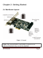
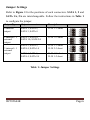
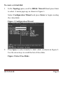
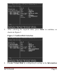
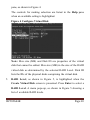
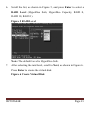
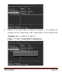
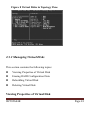
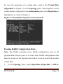
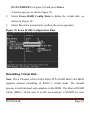
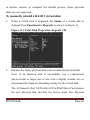
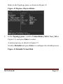
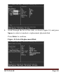
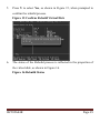
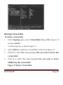
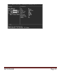
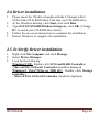
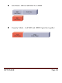
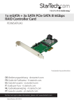
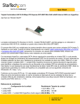
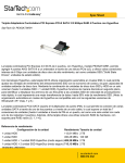
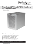
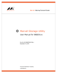
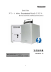
4 Channel 6-Port SATA 6Gb/s PCIe RAID Host Card User Manual Model: UGT-ST644R All brand names and trademarks are properties of their respective owners www.vantecusa.com Contents: Chapter 1: Introduction ...................................................... 3 1.1 Product Introduction ................................................ 3 1.2 Features.................................................................... 3 1.3 System Requirements .............................................. 4 1.4 Package Contents ..................................................... 4 Chapter 2: Getting Started ................................................. 5 2.1 Hardware Layout ..................................................... 5 2.2 Hardware Installation............................................... 7 2.3 Creating and Managing Virtual Disk ....................... 7 2.3.1 Creating Virtual Disks .................................. 7 2.3.2 Managing Virtual Disks .............................. 13 2.4 Driver Installation .................................................. 22 2.5 To Verify Driver Installation .................................. 22 2.6 What is HyperDuo? ............................................... 23 UGT-ST644R Page 2 Chapter 1: Introduction 1.1 Product Introduction This board is a single-chip, PCI Express to four SATA Gen III 6Gb/s channels host controller that brings server-class features to the desktop. This board enables the use of the industry’s newest and fastest hard drives at 6Gb/s while providing backward compatibility to legacy SATA 1.5Gb/s or 3Gb/s drives. It uses the same cable and connectors as previous SATA generations to ease integration. Besides, PCI Express 2.0 double the bandwidth of the existing PCI Express bus for faster data throughput. It will enhance system performance for every type of computer user. Each PCI-Express 2.0 lane provides up to 500MB/s of throughput. It is also backward compatible with previous generation of PCI Express 1.0 technology. Using the onboard RAID firmware, the 4 SATA drives attached to this controller can be easily configured as 4 individual ports with no RAID or with RAID 0, RAID 1, RAID 10, and HyperDuo. 1.2 Features Compliant with PCI-Express Specification v2.0 and backward UGT-ST644R Page 3 compatible with PCI-Express 1.x Compliant with Serial ATA Specification 3.0 PCI Express x2 interface, and compatible with PCI Express x4, x8 and x16 slots Supports communication speeds of 6.0Gbps, 3.0Gbps, and 1.5Gbps Hot plug and Hot Swap Supports Native Command Queuing (NCQ) Supports Port Multiplier FIS based switching or command based switching Compatible with SATA 6G, 3G and 1.5G Hard Drives Support RAID function: RAID 0, RAID 1, RAID 10 and HyperDuo Supports Windows® XP/Vista/7/8 and Server 2008 R2 1.3 System Requirements PCI Express x4, x8 or x16 slot Windows® XP/Vista/7/8 and Server 2008 R2. 1.4 Package Contents 1 x 4 Channel 6-Port SATA 6Gb/s PCIe RAID Host Card 1 x Driver CD 1 x User Manual 1 x Low Profile Bracket 2 x SATA Cables UGT-ST644R Page 4 Chapter 2: Getting Started 2.1 Hardware Layout Figure 1: Layout *Note: The internal SATA 3 and SATA 4 connectors are dedicated channels, they can not be disabled. UGT-ST644R Page 5 Jumper Settings Refer to Figure 1 for the positions of each connectors. SATA 1, 2 and SATA 1A, 2A are interchangeable. Follow the instructions in Table 1 to configure the jumper. Output Type Output connectors Description 4 internal output SATA 1, SATA 2, SATA 3, SATA 4 J1-J8 1-2 short 2 internal + 2 external output SATA 3, SATA 4, SATA 1A, SATA 2A J1-J8 2-3 short SATA 2, SATA 3, SATA 4, SATA 1A J1-J4 1-2 short J5-J8 2-3 short SATA 1, SATA 3, SATA 4, SATA 2A J1-J4 2-3 short J5-J8 1-2 short 3 internal + 1 external output Table 1: Jumper Settings UGT-ST644R Page 6 2.2 Hardware Installation 1. 2. 3. 4. 5. 6. 7. Turn off the power to your computer. Unplug the power cord and remove your computer’s cover. Locate to an empty PCI Express x4, x8, or x16 slot on the motherboard. To install the board, carefully align the card’s bus connector with the selected PCIe slot on the motherboard. Push the board down firmly. Attach your internal devices to the 4 Channel 6-Port SATA 6Gb/s PCIe RAID Host Card. Replace the slot bracket’s holding screw to secure the card. Secure the computer cover and reconnect the power cord. 2.3 Creating and Managing Virtual Disk 2.3.1 Creating Virtual Disks This section describes the steps for creating virtual disks using the BIOS Configuration Wizard. Press <Ctrl>+<M> to enter Marvell BIOS Setup UGT-ST644R Page 7 To create a virtual disk 1. In the Topology pane, scroll to HBA0: Marvell 0 and press Enter to select. A menu pops-up, as shown in Figure 1. Select Configuration Wizard and press Enter to begin creating the virtual disk. Figure 1 Configuration Wizard 2. Press Space to select/unselect a disk a disk, as shown in Figure 2. Use the arrow keys to scroll the list of free disks. Figure 2 Select Free Disks UGT-ST644R Page 8 3. After selecting the required disks, press Enter to continue, as shown in Figure 3. Figure 3 Confirm Disk Selection 4. Create Virtual Disk by configuring its setting in the Information UGT-ST644R Page 9 pane, as shown in Figure 4. The controls for making selection are listed in the Help pane when an available setting is highlighted. Figure 4 Configure Virtual Disk Note: Max size (MB) and Disk ID are properties of the virtual disk that cannot be edited. Max size (MB) in the size of the RAID virtual disk as determined by the selected RAID Level. Disk ID lists the IDs of the physical disks comprising the virtual disk. 5. RAID Level, as shown in Figure 5, is highlighted when the Create Virtual Disk screen is presented. Press Enter to select a RAID Level. A menu pops-up, as shown in Figure 5 showing a list of available RAID levels. UGT-ST644R Page 10 6. Scroll the list, as shown in Figure 5, and press Enter to select a RAID Level (HyperDuo Safe, HyperDuo Capacity, RAID 0, RAID 10, RAID 1). Figure 5 RAID Level Note: The default Level is HyperDuo Safe. 7. After selecting the raid level, scroll to Next, as shown in Figure 6. Press Enter to create the virtual disk. Figure 6 Create Virtual Disk UGT-ST644R Page 11 8. Please Y to select Yes, as shown in Figure 7, to confirm the creation of the virtual disk. The virtual disk is now listed in the Topology pane, as shown in Figure 7. Figure 7 Create Virtual Disk Confirmation UGT-ST644R Page 12 Figure 8 Virtual Disks in Topology Pane 2.3.2 Managing Virtual Disks This section contains the following topics: Viewing Properties of Virtual Disk Erasing RAID Configuration Data Rebuilding Virtual Disk Deleting Virtual Disk Viewing Properties of Virtual Disk UGT-ST644R Page 13 To view the properties of a virtual disk, scroll to the Virtual Disk (HyperDuo in Figure 9) in the Topology pane. The properties of the virtual disk are displayed in the Information pane when HyperDuo is highlighted, as shown in Figure 9. Figure 9 Virtual Disk Properties: Functional VD Erasing RAID Configuration Data Note: The RAID controller stores RAID configuration data on all physical disks that are part of a virtual disk. RAID configuration data must be erased on the physical disk before it can be used with another virtual disk. 1. In the Topology pane, select HyperDuo (HyperDuo > SSD 0: UGT-ST644R Page 14 OCZ-VERTEX2 in Figure 10) and press Enter. A menu pops-up, as shown Figure 10. 2. Select Erase RAID Config Data to delete the virtual disk, as shown in Figure 10. 3. Select Yes when prompted to confirm the erase operation. Figure 10 Erase RAID Configuration Data Rebuilding Virtual Disk Note: The 4 Channel 6-Port SATA 6Gb/s PCIe RAID Host Card BIOS supports manual rebuilding of RAID 1 virtual disks. The rebuild process is both initiated and complete in the BIOS. The Marvell RAID Utility (MRU), which runs in an OS environment, CANNOT be used UGT-ST644R Page 15 to initiate, resume, or complete the rebuild process. Spare physical disks are not supported. To manually rebuild a RAID 1 virtual disk 1. When a virtual disk is degraded, the Status of a virtual disk is changed from Functional to Degrade, as shown in Figure 11. Figure 11 Virtual Disk Properties: Degrade VD 2. Replace the faulty physical disk with an identical physical disk. Note: If an identical disk is unavailable, use a replacement physical disk or larger size or one with a slightly smaller size as determined the Gigabyte Rounding setting for the virtual disk. The 4 Channel 6-Port SATA 6Gb/s PCIe RAID Host Card detects the new physical disk and lists the device under Free Physical UGT-ST644R Page 16 Disks in the Topology pane, as shown in Figure 12. Figure 12 Replace Physical Disks 3. In the Topology pane, scroll to Virtual Disks (VD 0: New_VD in Figure 13), and press Enter to select. A menu pops-up, as shown in Figure 13 Scroll to Rebuild and press Enter to configure the rebuild process. Figure 13 Rebuild Virtual Disk UGT-ST644R Page 17 4. Scroll through the list of free disk, as shown Figure 14, and press Space to select or unselect a replacement physical disk. Press Enter to continue. Figure 14 Select Replacement Disk UGT-ST644R Page 18 5. Press Y to select Yes, as shown in Figure 15, when prompted to confirm the rebuild process. Figure 15 Confirm Rebuild Virtual Disk 6. The status of the Rebuild process is reflected in the properties of the virtual disk, as shown in Figure 16. Figure 16 Rebuild Status UGT-ST644R Page 19 Deleting Virtual Disk To delete a virtual disk 1. In the Topology pane, select Virtual Disk (New_VD in Figure 17) and press Enter. A menu pops-up, as shown Figure 17. 2. Select Delete to delete the virtual disk, as shown in Figure 17. 3. Press Y to select Yes when prompted Do you want to delete this virtual disk? 4. Press Y to select Yes when prompted Do you want to delete MBR from this virtual disk? Figure 17 Delete Virtual Disk UGT-ST644R Page 20 UGT-ST644R Page 21 2.4 Driver Installation 1. 2. 3. 4. 5. Please insert the CD driver bundle with the 4 Channel 6-Port SATA 6Gb/s PCIe RAID Host Card into your CD-ROM drive. At the Windows desktop, click Start, then click Run. Type D:\UGT-ST644R\Windows\Setup.exe, click OK. (Change D:\ to match your CD-ROM drive letter) Follow the on-screen instructions to complete the installation. Restart Windows to complete the installation. 2.5 To Verify Driver Installation 1. 2. 3. Right click My Computer and click Manage. Select Device Manager. Look for the following: Windows® XP: Double click SCSI and RAID Controller: -Marvell 92xx SATA 6G Controller should be displayed Windows® Vista/7/8/Server 2008 R2: Double click Storage controller: - Marvell 92xx SATA 6G Controller should be displayed UGT-ST644R Page 22 2.6 What is HyperDuo? HyperDuo is a technology created by Marvell Semiconductor, Inc. to optimize the performance of storage technology. This technology is built in to the UGT-ST644R card. It involves the combination of SSD as cache storage for the HDD drive to give unparalleled access speed. This tiering of SSD and HDD can give you 80% SSD performance at about the a third of the cost. Using safe mode, you mirror frequently access (hot files) in SSD speed and in Capacity mode, you combination SSD and HDD together with frequently access (hot files) in the SSD. You can easily setup the configuration in the card BIOS to optimize your system. Minimum Requirement: one SSD and one HDD. It can be setup in two modes of operation. UGT-ST644R Page 23 Safe Mode –Mirror SSD DATA to HDD Capacity Mode – Add SSD and HDD Capacities together UGT-ST644R Page 24