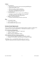
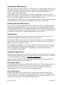
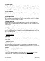
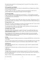
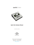
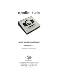
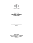
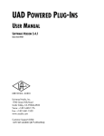
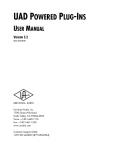
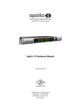
1
HIGH-RESOLUTION INTERFACE
with Realtime UAD Processing
Apollo Hardware Manual
UA Part Number 65-40424
Revision C
Customer Service & Technical Support:
+1-877-MY-UAUDIO (+1-877-698-2834)
International: +1-831-440-1176
www.uaudio.com
A Letter from Bill Putnam Jr.
Thank you for deciding to make the Apollo High-Resolution Audio Interface part of your music making
experience. We know that any new piece of gear requires an investment of time and money — and our goal is
to make your investment pay off. The fact that we get to play a part in your creative process is what makes our
efforts at UA meaningful, and we thank you for this.
In many ways, Apollo represents the single best example of what UA has stood for over its long history; from
UA’s original founding in the 1950s by my father, up through our current vision of delivering the best of both
analog and digital audio technologies. For more than 50 years, UA has produced some of the most coveted
pieces of analog recording equipment. More recently, we have pioneered cutting edge digital signal processing
which has allowed us to offer exacting digital emulations of classic analog hardware. Our unique expertise and
experience across both analog and digital have allowed us to make an audio interface that we think is very
special.
Starting with a high-quality analog front end, Apollo’s superior sonic performance serves as its foundation.
This is just the beginning, however, as Apollo is the only audio interface that allows you to run UAD plug-ins in
real time, tracking and monitoring using any of our plug-ins. Want to monitor yourself through a Neve®
console channel strip while tracking bass through a Fairchild or LA-2A compressor? Or how about tracking
vocals through a Studer® tape machine with some added Lexicon® reverb?* No problem. This is something
that only Apollo offers.
At UA, we are dedicated to the idea that technology should ultimately serve the creative process — not be a
barrier. These are the very ideals my father embodied as he invented audio equipment to solve problems in the
studio. With this in mind, we have crafted Apollo's Console software with an "analog workflow." The
convenience of this Console workflow, along with innovations such as the Console Recall plug-in, provide easeof-use and DAW integration for truly unique and productive experience.
As you get to know Apollo and incorporate it into your creative process, we hope that the excitement and pride
that we have put into it comes through. We also hope that it earns its way into your creative process, providing
you with great sound, exceptional plug-ins, and ease-of-use for years to come. Thanks.
Sincerely,
Bill Putnam Jr.
*All trademarks are recognized as property of their respective owners. Individual UAD Powered Plug-Ins sold separately.
Apollo Hardware Manual
ii
Welcome
Table Of Contents
A Letter from Bill Putnam Jr. ................................................................................................................................ ii Introducing Apollo ................................................................................................................................................ 4 What is Apollo? ................................................................................................................................................ 4 Apollo Features ................................................................................................................................................ 5 Hardware System Requirements ...................................................................................................................... 6 About Realtime UAD Processing ...................................................................................................................... 7 Combining with other UAD-2 devices .............................................................................................................. 7 Standalone Use................................................................................................................................................ 7 About Apollo Documentation ............................................................................................................................ 7 Front Panel ........................................................................................................................................................... 9 Rear Panel.......................................................................................................................................................... 13 Analog I/O ...................................................................................................................................................... 13 Digital I/O ...................................................................................................................................................... 14 Host I/O.......................................................................................................................................................... 16 Installation & Configuration............................................................................................................................... 17 Unit Placement .............................................................................................................................................. 17 Software Installation ..................................................................................................................................... 17 Registration and Authorization ...................................................................................................................... 17 Apollo System Configuration .......................................................................................................................... 17 Console Application ....................................................................................................................................... 17 Multi-Unit Cascading .................................................................................................................................... 17 Sound System Powering ................................................................................................................................. 17 Interconnections................................................................................................................................................. 18 Basic Setup ................................................................................................................................................... 18 Typical Setup ................................................................................................................................................. 19 Advanced Setup ............................................................................................................................................. 20 FireWire Basics................................................................................................................................................... 21 Mixing FireWire Speeds .................................................................................................................................. 23 Recommended Mixed Speed Setup ................................................................................................................ 23 Specifications .................................................................................................................................................... 24 Hardware Block Diagram.................................................................................................................................... 28 Troubleshooting.................................................................................................................................................. 29 Additional Resources.......................................................................................................................................... 30 Universal Audio Website ................................................................................................................................ 30 Technical Support .......................................................................................................................................... 30 Maintenance .................................................................................................................................................. 30 Voltage Selection ........................................................................................................................................... 30 Warranty ........................................................................................................................................................ 31 Repair Service ............................................................................................................................................... 31 Notices ............................................................................................................................................................... 32 Important Safety Information ........................................................................................................................ 32 Index .................................................................................................................................................................. 34 Apollo Hardware Manual
iii
Table Of Contents
Introducing Apollo
What is Apollo?
Apollo is a high-resolution audio interface with Realtime UAD Processing onboard that gives musicians and
recording engineers a no-compromise monitoring, tracking, and mixing solution. The combination of Apollo’s
high quality preamps, converters, and digital signal processing help you achieve the goal of making music
without the common latency and potential processor shortcomings of an all-native system. Apollo leverages
Universal Audio’s expertise in DSP acceleration, UAD Powered Plug-Ins, and analog hardware design by
integrating the latest cutting edge technologies in high-performance A/D-D/A conversion, DSP signal
reconstruction, and host connectivity. Apollo acts as both an audio interface with integrated DSP effects for
tracking and monitoring as well as a fully integrated UAD-2 DSP accelerator for mixing and mastering.
Apollo is available in two different configurations, which are differentiated by their DSP complement: Apollo
DUO with 2 SHARC DSPs, and Apollo QUAD with 4 SHARC DSPs. Apollo DUO and QUAD have identical I/O
features and functionality; the only difference is how much UAD plug-in processing power that is available for
tracking and mixing. Either way, you have an amazing sounding interface that can achieve the professional
sound quality of any era in recording history by using UAD Powered Plug-Ins.
Apollo uses FireWire or Thunderbolt for computer connectivity. FireWire 800 ensures the ability to use all of
Apollo’s I/O as well as its DSP processing. Thunderbolt is a high-speed data transmission protocol that
provides faster throughput and lower latency versus FireWire. The Thunderbolt Option Card is pre-installed in
Apollo’s option card slot, allowing Apollo to connect with Thunderbolt-enabled computers.
To fully realize the low latency potential of Apollo, the Console application is included and provides a familiar
analog mixing console interface where you can load your favorite combination of UAD plug-ins for Realtime UAD
Processing. Setting up two custom headphone mixes is quick and intuitive and you can also set up reverbs and
delays (or any other UAD effects) on two auxiliary buses for comfortable tracking of live microphones and
instruments.
Unison™ technology allows Apollo’s mic preamps to sound and behave like the world's most sought-after tube
and solid state preamps — including their all-important impedance, gain stage “sweet spots,” and circuit
behaviors. Based on breakthrough integration between Apollo’s digitally controlled analog mic preamps and its
onboard UAD processing, Unison lets you track through colorful preamp emulations like the bundled UA 610-B
Tube Preamp plug-in.
Achieving deep integration of Apollo’s features with your favorite digital audio workstation software is simple
thanks to the Console Recall plug-in that is compatible with VST, Audio Units, RTAS, and AAX 64 host software.
Simply place the Console Recall plug-in in any session and you have instant control over Apollo’s monitoring
options. The Console Recall plug-in can automatically recall the Console configuration within the DAW session
without having to manage separate Console preset files, so you can be sure that the Console mix you are
working with today will be accurately recalled tomorrow.
Done tracking? Use Apollo just like any other UAD-2 device for mixing in the DAW. The complete UAD Powered
Plug-Ins library works with Apollo, offering the best analog emulation plug-ins available from the best
companies in pro audio like Neve, SSL, Pultec, Teletronix, Studer, Lexicon, DBX, Roland, MXR, Harrison,
Empirical Labs, Manley, Ampex, and many more.* A single button in the Console lets you decide to “print” or
“monitor” the Realtime UAD Processing – so if you want the sound of your favorite console and tape machine
committed into your DAW, you can print those effects on the way in.
Quite simply, Apollo delivers the sound, feel, and flow of analog recording with all the conveniences of modern
digital equipment.
*All trademarks are recognized as property of their respective owners. Individual UAD Powered Plug-Ins sold separately.
Apollo Hardware Manual
4
Introducing Apollo
Apollo Features
•
•
•
•
•
Superior-sounding 18 x 24 audio interface with uncompromising UA analog design
Realtime monitoring and tracking with premium UAD Powered Plug-Ins
Additional mixing and mastering DSP horsepower for your sessions
FireWire 800 built-in
Thunderbolt connectivity available via Thunderbolt Option Card
Audio Interface
• Sample rates up to 192 kHz at 24-bit word length
• 18 x 24 simultaneous input/output channels:
• Eight channels of analog-to-digital conversion via mic, line, or high-impedance inputs
• 14 channels of digital-to-analog conversion via:
• Eight mono line outputs
• Stereo monitor outputs
• Two stereo headphone outputs
• 10 channels of digital I/O via:
• Eight channels ADAT Optical I/O with S/MUX for high sample rates
• Two channels coaxial S/PDIF I/O with sample rate conversion
• Two FireWire 800 ports for daisy-chaining other FireWire devices
Microphone Preamplifiers
• Four high-resolution, ultra-transparent, digitally-controlled analog mic preamps
• Front panel and software control of all preamp parameters
• Switchable low cut filter, 48V phantom power, 20 dB pad, polarity inversion, and stereo linking
• Unison™ technology for deep integration with UAD preamp plug-ins
Monitoring
• Stereo monitor outputs (independent of eight line outputs)
• Digitally-controlled analog monitor outputs maintains highest fidelity
• Front panel control of monitor levels and muting
• Two stereo headphone outputs with independent mix buses
• Independent front panel analog volume controls for headphone outputs
• Front panel pre-fader metering of monitor bus levels
• S/PDIF outputs can be set to mirror the monitor outputs
UAD-2 Inside
• DUO and QUAD models featuring two or four SHARC processors
• Realtime UAD Processing on all of Apollo’s analog and digital inputs
• Same features and functionality as other UAD-2 devices when used with DAW
• Can be combined with other UAD-2 devices for increased mixing DSP
• Includes UAD Powered Plug-Ins “Realtime Analog Classics Plus” bundle
• Complete UAD Powered Plug-Ins library is available online
Apollo Hardware Manual
5
Introducing Apollo
Software
• Console application:
• Analog-style mixer for realtime monitoring and tracking with UAD plug-ins
• Enables Realtime UAD Processing
• DSP mixer for realtime monitoring and tracking
• Remote control of Apollo features and functionality
• Virtual I/O for routing DAW tracks through Console
• Console Recall plug-in:
• Convenient access to Console’s monitor controls via DAW plug-in
• Saves Apollo configurations inside DAW sessions for easy recall
• VST, RTAS, AAX 64, and Audio Units plug-in formats
• UAD Meter & Control Panel application:
• Configures global UAD settings and monitors system usage
Other
• Easily updatable firmware
• 1U rack-mountable form factor
• One year warranty includes parts and labor
Hardware System Requirements
The host computer must meet the hardware system requirements below to use Apollo. For software system
requirements, refer to the Apollo Software Manual (see “About Apollo Documentation” on page 7).
Basic audio interface I/O functionality:
•
•
•
Available FireWire 800* or Thunderbolt** expansion port
4 gigabytes available disk space
Internet connection to download Apollo software
UAD-2 and Realtime UAD Powered Plug-Ins functionality:
•
•
Internet connection for registration, UAD plug-in authorization, & updates
Compatible VST, RTAS, AAX 64, or Audio Units plug-in host application software
*On Windows systems, a compatible PCIe to FireWire adapter card is required
**Apple Mac computer with available Thunderbolt or Thunderbolt 2 port required
Apollo Hardware Manual
6
Introducing Apollo
About Realtime UAD Processing
Apollo has the ability to run UAD Powered Plug-Ins in realtime. Apollo’s groundbreaking DSP + FPGA technology
enable UAD Powered Plug-Ins to run with latencies in the sub-2ms range, and multiple UAD plug-ins can be
“stacked” in series without additional latency. Realtime UAD Processing facilitates the ultimate sonic
experience while monitoring and/or tracking.
Realtime UAD Processing is a special function that is available only within the included Console software
application. All of Apollo’s analog and digital inputs can perform Realtime UAD Processing simultaneously, and
Console inputs with Realtime UAD Processing can be routed into the DAW for recording.
Important: Apollo, like other UAD-2 devices, can only load UAD Powered Plug-Ins that are specifically designed
to run on UAD-2 DSP accelerators. Native (host-based) plug-ins cannot run on the UAD-2 DSP.
Combining with other UAD-2 devices
Apollo can be used simultaneously with other UAD-2 devices (UAD-2 PCIe cards, UAD-2 SOLO/Laptop, UAD-2
Satellite, and/or another Apollo interface) in the same host computer system. Apollo simply adds to the DSP
availability (and with multiple Apollo units, additional I/O) when used with other UAD-2 devices during mixing,
increasing the DSP processing power so more UAD Powered Plug-Ins can be used. Up to four UAD-2 devices can
be combined in the same system; see the Apollo support web page for specific details.
Standalone Use
Although the Console application is required to unleash the full power of Apollo, the unit can be used as a
digital mixer with limited functionality without a connection to a host computer.
All currently active I/O assignments, signal routings, and monitor settings are saved to internal firmware when
Apollo is powered down and persist when power is re-applied. Therefore the last-used settings are always
available even when a host computer is not used.
Note that UAD plug-in instantiations are not retained on power down, because the plug-in files reside on the
host computer. However, if UAD plug-ins are active when Apollo’s connection to the host system is lost (if the
FireWire or Thunderbolt cable is unplugged), the current UAD plug-in configurations remain active for
processing until Apollo is powered down.
About Apollo Documentation
Documentation for all Apollo components is extensive, so instructions are separated by area of functionality, as
detailed below. All documentation is copied to the computer during software installation; Apollo documentation
can also be downloaded from our website at: www.uaudio.com/support/apollo
Note: All manuals are in PDF format. PDF files require a free PDF reader application such as Adobe Reader
(Windows and Mac) or Preview (included with Mac OS X).
Apollo Hardware Manual
The Apollo Hardware Manual contains complete information about the audio interface hardware. Included are
detailed descriptions for all Apollo hardware features, control functions, and connections. Refer to the
hardware manual (you’re reading it now) to learn all about interfacing the hardware with other devices,
operating the panel controls, clocking, specifications, and related information.
Apollo Software Manual
The Apollo Software Manual is the companion guide to the Apollo hardware manual. It contains detailed
information about how to configure and control Apollo’s software features using the Console application and
Console Recall plug-in. Refer to the Apollo Software Manual to learn how to operate these software tools and
integrate Apollo’s audio interface functionality into the DAW environment.
Apollo Hardware Manual
7
Introducing Apollo
UAD System Manual
The UAD System Manual is the complete operation manual for Apollo’s UAD-2 functionality and applies to the
entire UAD product line. It contains detailed information about installing and configuring UAD devices, the UAD
Meter & Control Panel application, how to use UAD Powered Plug-Ins within a DAW, obtaining optional plug-in
licenses at the UA online store, and more. It includes everything about UAD except Apollo-specific information
and individual UAD Powered Plug-In descriptions.
UAD Plug-Ins Manual
The features and functionality of all the individual UAD Powered Plug-Ins is detailed in the UAD Plug-Ins
Manual. Refer to this document to learn about the operation, controls, and user interface of each plug-in that
is developed by Universal Audio.
Direct Developer Plug-Ins
UAD Powered Plug-Ins includes plug-ins from our Direct Developer partners. Documentation for these 3rd-party
plug-ins are separate files that are written and provided by the plug-in developers themselves. The filenames
for these plug-ins are the same as the plug-in title names.
Thunderbolt Option Card
All documentation for using Apollo’s Thunderbolt Option Card is located on the Thunderbolt Support Page on
our website (there is no separate manual). Please review the information on the page carefully before installing
or using the device:
•
www.uaudio.com/support/thunderbolt
Host DAW Documentation
Each host DAW application has its own particular methods for configuring audio interfaces and using plug-ins.
Refer to the host DAW manufacturer’s documentation for specific instructions about using audio interface and
plug-in features within the DAW.
Helpful videos about setting up Apollo with various DAWs are available on our website:
•
www.uaudio.com/videos
Support Pages
The latest technical information about Apollo is posted on the Universal Audio website. Our support pages may
contain updated, late-breaking information that is not available in other publications. Please visit the Apollo
support page at:
•
www.uaudio.com/support
Technical Support
Universal Audio provides free customer support to all registered Apollo users. Our support specialists are
available to assist you via email and telephone during our normal business hours, which are from 9am to 5pm,
Monday through Friday, Pacific Standard Time.
Telephone
USA toll-free:
International:
+1-877-698-2834 (1-877-MY-UAUDIO)
+1-831-440-1176
Online Support
To request online support via email, please visit our support pages at uaudio.com/support, then click the
“Submit Support Ticket” button on the right side of any support page to create a help ticket.
Apollo Hardware Manual
8
Introducing Apollo
Front Panel
This section describes the features and functionality of all controls and visual elements on the Apollo front
panel. Note that all front panel functions, except the headphone volume knobs and power switch, can be
controlled remotely with the included Console software application.
(1) Hi-Z Inputs 1 & 2
The Hi-Z (high impedance) JFET direct inputs are for connecting low-level passive devices such as electric
guitar and bass instruments into channels 1 & 2 for A/D conversion. Connect only ¼” unbalanced TS phone
plugs to these inputs; TRS plugs cannot be used.
The Hi-Z inputs have an ultra-high input impedance of 2.2 Megohms that eliminates impedance loading,
preserving the high-frequency content of signals from sources with high impedance outputs (such as electric
guitar pickups). Hi-Z input gain levels are adjusted with the Preamp control for the associated channel.
Automatic Input Detection
Hi-Z inputs 1 & 2 use the same A/D converter channels as the corresponding Mic 1 & 2 and Line 1 & 2 inputs.
When a device is plugged into a Hi-Z input, the Mic and Line inputs for the channel are overridden, the Mic/Line
switch for the channel has no effect, and the stereo link is severed (if active). To use Mic or Line inputs 1 or 2,
its corresponding Hi-Z input must be disconnected.
(2) Preamp Gain & Channel Select Knob
This rotary encoder with integrated pushbutton serves two functions. Rotating the knob adjusts the preamp
gain for the selected input channel, and pushing the knob selects which preamp channel (1 – 4) is affected by
the front panel preamp controls.
Preamp Gain
The preamp gain of analog inputs 1 – 4 is adjusted with this control. The channel to be adjusted (1 – 4) is set
with the Channel Select function. The input to be adjusted (Mic, Line, or Hi-Z) is determined by the state of the
channel’s Mic/Line switch or Hi-Z input (if connected).
Rotating the knob clockwise increases the preamp gain for the selected channel. The available gain range for
preamp channels 1 – 4 is 10 dB to 65 dB for the Mic, Line, and Hi-Z inputs.
Note that it takes more than a full revolution of the Preamp Gain Knob to move through the available range.
This increases the control resolution for more precise preamp gain adjustments.
Only analog inputs 1 – 4 have input gain adjustment via the mic preamp controls. To adjust signal levels for
inputs 5 – 18, use the output level controls of the devices that are connected to those inputs.
Channel Select
Pushing the Preamp Knob changes the currently selected channel, which determines which input (1 – 4) is
adjusted by the front panel preamp controls. A channel is selected for adjustment when its Channel Select
Indicator LED (located above the channel 1 – 4 input meters; see #11 on page 11) is illuminated.
Apollo Hardware Manual
9
Front Panel
Each time the knob is pushed, the selected preamp channel is incremented. If stereo linking is active, the
stereo pairs are selected.
(3) Preamp Gain Level Indicator
The amount of preamp gain for the selected channel is displayed with the ring of illuminated green indicator
LEDs surrounding the Preamp Knob.
The LEDs are relative levels and are not calibrated to indicate any specific dB value. However, precise
numerical dB gain values for the preamps are displayed in the Console application.
(4–9) Preamp Settings
This set of six buttons control the preamp options for input channels 1 – 4. Press the buttons to toggle the
setting. The current state of each preamp option button is indicated by the Preamp Options LEDs (#10 on page
11). Each button function is detailed below.
(4) Mic/Line
This button switches between the channel’s Mic and Line inputs on the rear panel. This button has no effect if
the channel’s Hi–Z input is connected (when a cable is inserted into the Hi-Z input, the Mic/Line LED turns off).
(5) Low Cut Filter (
)
When enabled, the channel’s input signal passes through a low cut (high pass) filter. This 2nd-order coincidentpole filter has a cutoff frequency of 75 Hz with a slope of 12 dB per octave.
The Low Cut filter affects the Mic, Line, and Hi-Z inputs. Low Cut is typically used to eliminate rumble and
other unwanted low frequencies from the input signal.
(6) Phantom Power (+48V)
When enabled, 48 volts of phantom power is supplied to the channel’s rear panel Mic input. Most modern
condenser microphones require 48V phantom power to operate. This option can only be activated when the
Mic/Line switch (#4) is set to Mic.
Note: Depending on the current configuration of the hardware and software, there may be a delay when
changing the 48V state to minimize the clicks/pops that are inherent when engaging phantom power. The
+48V LED will blink rapidly during any delay.
(7) Pad
When enabled, the channel’s microphone input signal level is attenuated by 20 dB. Pad does not affect the Line
or Hi-Z inputs.
Pad is used to reduce signal levels when overload distortion is present at low preamp gain levels, such as when
particularly sensitive microphones are used on loud instruments, and/or if the A/D converter is clipping.
(8) Polarity (ø)
When enabled, the polarity (aka “phase“) of the input channel’s signal is inverted. Polarity affects the Mic,
Line, and Hi-Z inputs.
Polarity inversion can help reduce phase cancellations when more than one microphone is used to record a
single source.
(9) Stereo Link
This button links the preamp controls of adjacent channels together (1 & 2 or 3 & 4) to create stereo input
pairs. When channels are linked as a stereo pair, any preamp control adjustments will affect both channels of
the stereo signal identically.
Only the same type of inputs can be linked (Mic/Mic or Line/Line). The Hi-Z inputs cannot be linked.
Apollo Hardware Manual
10
Front Panel
(10) Preamp Options LEDs
These seven LEDs display the state of the preamp option button settings for the currently selected channel.
Each LED is illuminated when its associated option is active. When the channel selection is changed, the LED
states are updated to reflect the current settings for the selected channel.
(11) Channel 1 – 4 Select LEDs
The currently selected channel is indicated by the LEDs above input level meters 1 – 4. When a channel (or
channels, when stereo linked) is selected, its associated LED is illuminated. The currently selected channel is
incremented when the Preamp Knob (#2) is pressed.
Note: The numbers for channels 5 – 8 do not illuminate.
(12) Input Level Meters
The 10-segment LED meters display the signal peak input levels for analog channels 1 – 8 at the input to the
A/D converters. The dB values of the input meter LEDs are indicated between the meters for channels 4 and 5.
When digital clipping occurs, the red “CLIP” LED illuminates. Avoid digital clipping at the channel’s A/D
converter by reducing the channel’s input level at its source, and/or in the case of channels 1 – 4, by reducing
the preamp gain or engaging the Pad (#7) and readjusting gain as needed.
(13) Power Indicator (UA Logo)
The Universal Audio logo illuminates when the external power supply is properly connected to the AC outlet and
the power input on the rear of the unit, and the Power switch (#22) is in the up position.
Clock LEDs
The Internal (“INT”) and External (“EXT”) Clock LEDs indicate the source and status of the system master clock.
The clock source is specified within the Console application.
(14) Internal Clock
When Apollo is using its internal clock as the master clock source, the Internal Clock LED is solid green. When
set to external clock, this LED is not illuminated.
(15) External Clock
When Apollo is set to use an external clock as the master clock source and a valid clock signal is detected at
the specified port, the External Clock LED is solid green. Apollo can be configured to use an external clock from
the Word Clock, S/PDIF, or ADAT inputs. When set to internal clock, this LED is not illuminated.
If the External Clock LED is red, Apollo is configured to use an external clock but it cannot lock to the clock
source and/or sample rate specified in the Console application.
Important: Apollo's sample rate must be manually set (in the Console application) to match the incoming
clock's sample rate.
Apollo Hardware Manual
11
Front Panel
(16) UAD Link LED
The UAD Link LED is a system status indicator. The LED is solid green when Apollo is connected to (and properly
communicating with) the host computer system via FireWire or Thunderbolt, and off when not connected. When
blinking red/green, the UAD drivers are not properly loaded. When solid red, the LED indicates an error state.
The Apollo software must be properly installed and configured on the host computer to enable the UAD Link,
and the UAD Link must be active to use Apollo with any/all computer operations. The only time the link is not
required is when Apollo is used “standalone” without a computer (see “Standalone Use” on page 7).
(17) Monitor Output Level Meters
The 10-segment LED meters display the signal peak output levels for monitor outputs 1 & 2 (Left & Right) at
the output of the D/A converters. These meters are before the Monitor Level control (pre-fader) and reflect the
D/A converter levels regardless of the current Monitor Level and Headphone Level knob settings.
The dB values of the monitor meter LEDs are indicated between the left and right channel meters. When digital
clipping occurs, the red “CLIP” LED illuminates. Avoid clipping at the monitor D/A converters by reducing the
monitor bus output level and/or the channels feeding the monitor output bus.
(18) Monitor Level and Mute Knob
This rotary encoder serves two functions. Rotating the knob adjusts the monitor output level, and pushing the
knob mutes the monitor outputs.
Monitor Level
Rotating the knob clockwise increases the signal level at monitor outputs 1 & 2 on the rear panel. Although this
is a digital control, the monitor volume is attenuated in the analog domain, after D/A conversion (digitallycontrolled analog volume). This method provides the utmost monitoring fidelity, in contrast to digital volume
controls that reduce levels by truncating the word length (“dropping bits”).
Monitor Mute
Pushing the Monitor knob toggles the mute state of the signals at monitor outputs 1 & 2 on the rear panel.
When the monitor outs are muted, the Monitor Level Indicator (#19) is red.
Note: Monitor Mute does not mute the headphone outputs.
(19) Monitor Level Indicator
The signal level at the rear panel monitor outputs is displayed with this ring of illuminated indicator LEDs
surrounding the Monitor Level knob. The LEDs are green when the monitor outputs are active, and red when the
monitor outputs are muted. This meter is after the Monitor Level control (“post fader”). It indicates relative
levels only and is not calibrated to specific dB values.
(20) Headphone Level Knobs 1 & 2
These analog knobs control the volume of Headphone Outputs 1 & 2 on the front panel. Each headphone output
has its own volume control. Headphone levels are attenuated in the analog domain (after D/A conversion) for
maximum fidelity.
(21) Headphone Outputs 1 & 2
These ¼” stereo TRS phone jacks are for connecting stereo headphones to Apollo. Headphone outputs 1 & 2 are
individually addressable by the device drivers and the Console application. Unique mixes can be created for
each headphone output, or they can be switched to mirror the monitor outputs in the Console application. When
mirroring the monitor outputs, the headphone outputs are unaffected by Monitor Mute (#18), to facilitate
recording/tracking with headphones while the monitor speakers are muted.
(22) Power Switch
This switch applies power to Apollo. When the unit is powered on, the Universal Audio logo is illuminated. The
external power supply must be properly connected for this switch to function.
Apollo Hardware Manual
12
Front Panel
Rear Panel
Analog I/O
(1) Monitor Outputs 1 & 2
These balanced ¼” TRS phone jacks are line-level analog outputs typically used for connection to a stereo
loudspeaker monitoring system. The signal levels at these outputs are controlled with the Monitor Level knob
(#18). Unbalanced ¼” TS cables can also be used.
The Monitor Outputs are completely independent from the eight Line Outputs. By default, the “1–2” or “Main”
outputs from a DAW are routed to these outputs. Stereo panning of input signals routed to these outputs is
defined within the Console and/or DAW applications.
The S/PDIF output can be configured to mirror the Monitor Outputs; see “(7) S/PDIF Ports” on page 15 for
details.
(2) Line Outputs 1 – 8
The individually addressable line-level analog outputs use balanced ¼” TRS phone jacks. Unbalanced ¼” TS
cables can also be used.
The Line Outputs can be configured in adjacent pairs to use –10 dBV or +4 dBu reference levels. This function
is configured in the Console application.
(3) Line Inputs 1 – 8
The individually addressable line-level analog inputs use balanced ¼” TRS phone jacks. Unbalanced ¼” TS
cables can also be used. The Hi-Z inputs override the Line Inputs on channels 1 & 2.
Line Inputs 5 – 8 can be configured in adjacent pairs to use –10 dBV or +4 dBu reference levels; this function
is configured in the Console application. Line Inputs 1 – 4 are fixed at a reference level of +4 dBu, however
gain for inputs 1 – 4 is continuously variable.
Adjacent input channel pairs can be linked for easy stereo adjustments. Stereo links for channels 1-2 and 3-4
can be established using the Link button on the front panel or in the Console application; channels 5-6 and 7-8
can be linked using the Console application only.
(4) Microphone Inputs 1 – 4
The balanced Microphone inputs use locking XLR connectors. Pin 2 is wired positive (hot). Inputs 1 – 4 are
switched between Mic and Line using the front panel controls. The Hi-Z inputs override the Mic inputs on
channels 1 & 2.
48V phantom power is available via the front panel switch (when the channel is selected), or from within the
Console application.
Apollo Hardware Manual
13
Rear Panel
Adjacent channel pairs can be linked for easy stereo adjustments. Stereo links for channels 1–2 and 3–4 can
be established using the front panel Link button or the Console application.
(5) Power Input
The included external power supply plugs into this 4-pin locking XLR jack. To eliminate risk of circuit damage,
connect only the factory-supplied power supply. Use the Power switch on the front panel to power the unit on
and off.
Important: Do not disconnect the power supply while Apollo is in use, and confirm the Power switch is in the
“off” position before connecting or disconnecting the power supply.
Digital I/O
(6) ADAT S/MUX Optical Ports
These ports use the ADAT Lightpipe Optical Interface protocol for interconnecting with other audio hardware
devices in the digital domain. Two ADAT inputs and two ADAT outputs are provided, routing a total of eight
channels of digital audio. The channels routed by these ports depend on the current system sample rate.
At sample rates of 44.1 kHz and 48 kHz, the original ADAT protocol is used, and eight audio channels are routed
on one ADAT port. At higher sample rates, industry standard S/MUX is used to maintain high-resolution
transfers.
Important: To utilize all eight channels with the optical ports at sample rates of 88.2 kHz and above, ADAT
ports 1 & 2 must both be connected to the other device, and the other device must also support the ADAT
S/MUX protocol.
The following behaviors apply to the ADAT ports:
•
•
•
At sample rates of 44.1 kHz and 48 kHz, port 1 supports eight channels of I/O. Output 2 mirrors
output 1, and input 2 is disabled.
At sample rates of 88.2 kHz and 96 kHz, up to four channels of audio is routed per port (eight channels
total, when both ports are used).
At sample rates of 176.4 kHz and 192 kHz, up to two channels of audio is routed per port (four
channels total, when both ports are used). Only four ADAT channels are supported at 176.4 kHz and
192 kHz.
Apollo Hardware Manual
14
Rear Panel
The ADAT port channel assignments described above are summarized in this table:
ADAT PORT CHANNEL ROUTING
Sample Rate (kHz) Input Port 1 Input Port 2 Output Port 1
Output Port 2
44.1 & 48
1–8
Disabled
1–8
1 – 8 (mirror of port 1)
88.2 & 96
1–4
5–8
1–4
5–8
176.2 & 192
1–2
3–4
1–2
3–4
Note: The ADAT ports use TOSLINK JIS F05 optical connectors. Some devices use this type of connector for
optical S/PDIF connections. However, Apollo’s ADAT ports do not support the S/PDIF protocol.
(7) S/PDIF Ports
The S/PDIF ports provide two channels of digital I/O with resolutions up to 24-bit at 192 kHz via female phono
(RCA) connectors. For optimum results, use only high-quality 75-ohm cables specifically designed for S/PDIF
digital audio.
Sample rate conversion can be enabled on the S/PDIF input; this setting is in the Console application. When the
sample rate of the incoming S/PDIF signal does not match the sample rate specified in the Console application,
the S/PDIF signal is converted to match Apollo’s sample rate. If Apollo is set to use S/PDIF as the master clock
source, sample rate conversion is inactive.
The S/PDIF output can be configured to mirror the Monitor outputs, for patching the stereo Monitor signal to the
stereo S/PDIF input of other devices. This function is configured in the Console application.
(8) Word Clock In
Apollo’s internal clock can be synchronized (slaved) to an external master word clock. This is accomplished by
setting Apollo’s clock source to Word Clock within the Console application, connecting the external word clock’s
BNC connector to Apollo’s word clock input, and setting the external device to transmit word clock. If Apollo is
the last device in the clock chain, the Termination switch (#10) should be engaged.
Important: Apollo's sample rate must be manually set to match the incoming clock's sample rate.
Note: Apollo can be synchronized to an external “1x” clock signal only. Superclock, overclocking, and
subclocking are not supported.
(9) Word Clock Out
This BNC connector transmits a standard (1x) word clock when Apollo is set to use its internal clock. The clock
rate sent by this port matches the current system sample rate, as specified within the Console application.
When Apollo is set to use external word clock as its clock, Apollo is a word clock slave. If the incoming external
word clock is within ±0.5% of a supported sample rate (44.1 kHz, 48 kHz, 88.2 kHz, 96 kHz, 176.4 kHz, 192
kHz), Word Clock Out will mirror Word Clock In with a slight phase delay (about 40ns).
Because Apollo’s word clock output is not a true mirror of the word clock input, word clock out should not be
used to daisy chain the word clock if Apollo is in the middle of the word clock chain. The correct method to
connect Apollo in the middle of a word clock chain is to use a T-connector at Apollo’s word clock input and
leave Apollo’s word clock output unconnected (the Termination switch should not be engaged in this scenario).
Apollo Hardware Manual
15
Rear Panel
(10) 75 Ohm Word Clock Termination Switch
This pushbutton switch provides internal 75-ohm word clock input signal termination when required. Word
clock termination is active when the switch is engaged (depressed).
Apollo’s termination switch should only be engaged when Apollo is set to sync to external word clock and it is
the last device at the receiving end of a word clock cable. For example, if Apollo is the last “slave” unit at the
end of a clock chain (when Apollo’s word clock out port is not used), termination should be active.
Host I/O
Apollo can be connected to the host computer system via FireWire or Thunderbolt. When Apollo is properly
configured and communicating with the host computer, the UAD Link LED (#16 on front panel) is solid green.
Important: Connect only one Apollo FireWire or Thunderbolt port to the host computer.
(11) FireWire 800 Ports
FireWire is used for connecting to the host computer system when the Thunderbolt ports are not in use.
When FireWire is used for the host connection, the second FireWire port can be used for daisy-chaining other
FireWire devices (see the Apollo support web page for important constraints).
Although the two FireWire 800 ports are numbered, they are functionally identical and either port can be used
for FireWire connections.
For additional FireWire information and recommended interconnections, see “FireWire Basics” on page 21.
Note: Apollo cannot be bus powered and it does not supply bus power from its FireWire ports to other devices.
(12) Expansion Bay
The expansion bay is where the Universal Audio Thunderbolt Option Card is installed. Thunderbolt is used
instead of FireWire when connecting to Thunderbolt-enabled host computer systems.
The Thunderbolt Option Card is pre-installed at the factory. For complete details about using Thunderbolt with
Apollo, please visit:
•
www.uaudio.com/support/thunderbolt
Note: Earlier Apollo units did not include the Thunderbolt Option Card. However, the earlier units can be easily
retrofitted with the user-installable Thunderbolt Option Card (sold separately).
Apollo Hardware Manual
16
Rear Panel
Installation & Configuration
Unit Placement
Apollo may get hot during normal operation if it doesn’t receive adequate airflow circulation around its chassis
vents. For optimum results when mounting Apollo in a rack, leaving at least one empty rack space above the
unit to allow adequate airflow for cooling is recommended.
Software Installation
The Apollo software must be installed to use Apollo and UAD Powered Plug-Ins. The UAD Powered Plug-Ins
software installer contains the Apollo software and drivers. For complete and detailed software installation
procedures, refer to the UAD System Manual (see “About Apollo Documentation” on page 7).
To obtain the latest UAD software installer, visit: www.uaudio.com/downloads
Registration and Authorization
Apollo must be registered and authorized at my.uaudio.com to unlock UAD plug-ins that are bundled with the
product. Registration only needs to be completed once, however authorization should be completed each time
the Apollo software is updated. For complete and detailed registration and authorization procedures, refer to
the UAD System Manual.
Apollo System Configuration
For complete details about setting up the Apollo system, including how to integrate with a DAW and related
information, refer to the Apollo Software Manual (see “About Apollo Documentation” on page 7).
Console Application
The Console application is the main software interface for the Apollo hardware. Console’s function is to control
Apollo and its digital mixing and Realtime UAD Processing capabilities. Console can also be used to configure
Apollo’s audio interface I/O settings such as sample rate, clock source, and reference levels.
For complete details about how to operate Console, refer to the Apollo Software Manual.
Multi-Unit Cascading
When more I/O is needed, multiple Apollo units can be cascaded together in a multiple-unit configuration.
Operating a multi-unit system is similar to that of a single-unit system.
For complete details about multi-unit cascading, including wiring diagrams, refer to the Apollo Software
Manual.
Sound System Powering
As with any sound system, to avoid audio spikes in your speakers, the following steps are recommended:
1. Apply power to the speakers last, after all other devices (including Apollo) are powered on.
2. Turn off the speakers first, before all other devices (including Apollo) are powered off.
Apollo Hardware Manual
17
Installation & Configuration
Interconnections
Basic Setup
This diagram illustrates a simple Apollo setup that might be used by an individual musician/engineer for
recording and mixing.
The example shows an electric guitar connected to the Hi-Z input of channel 1 and a microphone connected to
the XLR input of channel 2 so they can both be recorded simultaneously. Headphones are used during tracking
to avoid track bleed from the monitor speakers (Monitor Mute is enabled during tracking). The left and right
monitor outputs are connected to a loudspeaker system for use during mixdown.
Key points for this example:
•
•
•
•
Two preamp channels are used (electric guitar and microphone)
Mic/Line switch for channel 2 is set to “Mic”
Monitor outputs are connected to powered monitors (or an amp+speaker system)
If connecting to a Thunderbolt computer via the Thunderbolt Option Card, the FireWire connections
shown here would not be used
Apollo Hardware Manual
18
Interconnections
Typical Setup
This diagram illustrates an Apollo setup that might be used by two musicians that are recording
simultaneously. In this setup, only analog devices are connected; digital I/O is not used.
The example shows an electric guitar and electric bass connected to the Hi-Z inputs. Microphones are
connected to XLR inputs of channel 3 and 4, and a stereo keyboard instrument is connected to line inputs 5
and 6. Both headphone outputs are used during tracking and the left/right monitor outputs are connected to a
loudspeaker system for mixdown.
Key points for this example:
•
•
•
Mic/Line switch for channels 3 and 4 are set to “Mic”
Unique mixes can be sent to each headphone output for “more me” during tracking
If connecting to a Thunderbolt computer via the Thunderbolt Option Card, the FireWire connections
shown here would not be used
Apollo Hardware Manual
19
Interconnections
Advanced Setup
This diagram illustrates a more complex Apollo setup that might be used for recording an entire ensemble,
utilizing both analog and digital I/O.
In addition to the connections in the previous example, four additional microphones are connected to UA’s
4-710d Four-Channel Tone-Blending Mic Preamp w/ Dynamics. The 4-710d performs A/D conversion on these
mics and their signals are digitally routed into Apollo via the ADAT Optical Interface. Apollo is the master clock
source so the 4-710d is set to use external word clock (and a 75-ohm BNC word clock cable is interconnected).
A digital recorder is connected to the S/PDIF outputs and a tuner is connected to analog line output 7.
Key points for this example:
•
•
•
•
Mic/Line switch for channels 3 and 4 are set to “Mic”
Four additional mic preamps from UA’s 4-710d are routed into Apollo via ADAT Lightpipe
Apollo is the master clock device; the 4-710d clock source is set to external word clock and the 4-710d
Termination switch is engaged
(Alternately, the 4-710d could be used as the master clock by setting the 4-710d to internal clock,
setting Apollo to external ADAT clock, and eliminating the word clock cable)
If connecting to a Thunderbolt computer via the Thunderbolt Option Card, the FireWire connections
shown here would not be used
Apollo Hardware Manual
20
Interconnections
FireWire Basics
FireWire (also known as “IEEE 1394” and “i.Link”) is a high-speed serial data interconnection protocol that is
used to transfer digital data between devices. FireWire is commonly used to interconnect computer systems to
hard drives, audio interfaces, and digital camcorders. A complete discussion of FireWire is beyond the scope of
this manual, but some of the main points and how they apply to Apollo are covered below.
FireWire vs. USB
FireWire is considered superior to USB for audio purposes because it does not rely on the host processor to
manage low-level data housekeeping (among other reasons). FireWire typically outperforms USB at the same
rated speeds.
FireWire Bus
FireWire devices are connected to a FireWire “bus” which is comprised of all devices in the serial data stream.
The FireWire specification supports up to 63 devices per FireWire bus.
Many FireWire devices and host computers have more than one FireWire connector, but these connectors almost
always attach to the same FireWire bus (most computers do not have more than one FireWire bus). It is possible
to add another FireWire bus to a computer, typically by adding a PCIe-to-FireWire or ExpressCard-to-FireWire
adapter card.
Bus Power
Some FireWire devices can be “bus powered” which means the device derives its operating electricity from the
FireWire bus itself without a power supply of its own. Apollo cannot be bus powered and it does not supply bus
power from its FireWire ports to other devices.
Powering Down
Powering down or disconnecting Apollo when UAD plug-ins are loaded could cause session data loss and/or
unpredictable behavior. Quit all UAD host applications (DAW, Console, UAD Meter & Control Panel) before
disconnecting Apollo.
FireWire 800 vs. FireWire 400
The most common FireWire devices are available in two speeds: FireWire 400 (IEEE 1394a), which supports
transfer speeds up to 400 megabits per second, and FireWire 800 (IEEE 1394b), which supports up to 800
megabits per second. It's usually possible to determine the speed of the FireWire device by the type of FireWire
connector it uses. Apollo is a FireWire 800 device.
FireWire Connectors
FireWire 800 and FireWire 400 devices use different connectors, as illustrated below. This helps to differentiate
between the two device speeds; the connectors are not interchangeable.
FireWire 400 connectors
FireWire 400 devices typically have two types of connector: 4-pin and 6-pin. The small 4-pin FireWire 400
connector is common on digital camcorders and Windows notebook computers. The 6-pin connector is more
common with hard drives and audio devices.
Apollo Hardware Manual
21
FireWire Basics
FireWire 800 connector
FireWire 800 devices use a 9-pin connector. 9-pin to 6-pin FireWire adapter cables are available to connect
FireWire 800 devices to a FireWire 400 bus (with half the bandwidth).
Apollo has two FireWire 800 ports to facilitate easy daisy chaining with other FireWire devices.
FireWire Repeaters and Chains
FireWire devices can be connected to each other serially in a “daisy chain,” connected to a central device such
as a computer with multiple FireWire ports or a peripheral FireWire repeater, or any combination of the two in a
“tree chain” topology.
Apollo can function as a FireWire repeater, by using the unused port on the unit to connect other FireWire
devices. Note that Apollo does not supply FireWire bus power to downstream devices.
The examples below show a few of the many interconnection possibilities using daisy chains and repeaters.
Apollo Hardware Manual
22
FireWire Basics
Mixing FireWire Speeds
Although FireWire 400 and FireWire 800 devices can be connected to the same FireWire bus via a repeater or
daisy chain, special precautions must be observed to maximize bandwidth in these situations.
FireWire 800 devices on a FireWire 400 bus
FireWire 800 devices are backwards compatible and can be connected to a FireWire 400 bus using a 9-pin to 6pin FireWire cable or adapter. However in this scenario any 800 megabit-capable devices on the bus (including
Apollo) will operate at a maximum of 400 megabits because FireWire bandwidth cannot exceed the maximum
bus speed of the host computer.
FireWire 400 devices on a FireWire 800 bus
FireWire 400 devices can be connected to a FireWire 800 bus using a 6-pin to 9-pin FireWire cable or adapter.
However, if the FireWire 800 devices are located after the FireWire 400 devices in the daisy chain, all FireWire
devices will operate at a maximum of 400 megabits because the FireWire 400 devices force all subsequent
devices to run at FireWire 400 speeds.
It is possible to configure a FireWire bus to run at both FireWire 400 and FireWire 800 speeds simultaneously if
the host computer bus is FireWire 800, supporting maximum throughput with a mix of FireWire 400+FireWire
800 devices. This is accomplished by putting any/all FireWire 400 devices AFTER any/all FireWire 800 devices in
a daisy chain or tree chain. If (and only if) FireWire 400 devices are attached to a FireWire 800 bus after the
end of all FireWire 800 devices in a daisy chain or tree chain, the FireWire 800 devices will operate at 800
megabits while the FireWire 400 device operates at 400 megabits. The diagram below illustrates the
recommended configuration when Apollo is sharing a FireWire 800 bus with FireWire 400 devices.
Recommended Mixed Speed Setup
The example below shows the correct method of interconnecting FireWire 800 and FireWire 400 devices to a
FireWire 800 computer bus. Any mixture daisy chains, repeaters, and/or tree chains may be used, as long as all
the FireWire 400 devices are placed after all the FireWire 800 devices.
This FireWire bus runs optimally at both 800 megabits and 400 megabits because
the FireWire 400 device is located AFTER the FireWire 800 devices in the setup.
Apollo Hardware Manual
23
FireWire Basics
Specifications
All specifications are typical performance unless otherwise noted, tested under the following conditions: 48 kHz
internal sample rate, 24-bit sample depth, 20 kHz measurement bandwidth, with balanced output.
SYSTEM
I/O Complement
Microphone Inputs
High-Z Instrument Inputs
Analog Line Inputs
Analog Line Outputs
Analog Monitor Outputs
Headphone Outputs
ADAT
S/PDIF
FireWire 800 ports (IEEE 1394b)
Thunderbolt ports (Thunderbolt 2 compatible)
Word Clock
A/D – D/A Conversion
Supported Sample Rates (kHz)
Bit Depth Per Sample
Simultaneous A/D conversion
Simultaneous D/A conversion
Analog Round-Trip Latency
Analog Round-Trip Latency with up to four serial
UAD plug-ins via Console application
ANALOG I/O
Analog Inputs 1 – 8
Frequency Response
Channel Separation
Microphone Inputs 1 – 4
Connector Type
Phantom Power
Dynamic Range
Signal-to-Noise Ratio
Total Harmonic Distortion + Noise
Equivalent Input Noise
Common-Mode Rejection Ratio (CMRR)
Default Input Impedance
Gain Range
Pad Attenuation
Maximum Input Level (@ Minimum Gain, with Pad)
Maximum Input Level (@ Maximum Gain, with Pad)
Apollo Hardware Manual
Four
Two
Eight
Eight
Two (one stereo pair, independent L/R mix buses)
Two stereo (independent L/R mix buses)
Up to eight channels via dual I/O ports with S/MUX
One stereo input, one stereo output
Two
Two (via Thunderbolt Option Card)
One input, one output
44.1, 48, 88.2, 96, 176.4, 192
24
Eight channels
14 channels
1.1 milliseconds @ 96 kHz sample rate
1.1 milliseconds @ 96 kHz sample rate
20 Hz – 20 kHz, ±0.1 dB
Greater than 120 dB
Female XLR Balanced (pin 2 positive)
+48V (switchable per mic input)
118 dB (A–weighting)
118 dB (A–weighting)
–110 dBFS
–128 dB
Greater than 60 dB (10’ cable)
5.4K Ohms (variable via Unison preamp plug-ins)
+10 dB to +65 dB
20 dB (switchable per mic input)
23.9 dBV
–31.1 dBV
(continued)
24
Specifications
Hi–Z Inputs
Connector Type
Dynamic Range
Signal-to-Noise Ratio
Total Harmonic Distortion + Noise
Input Impedance
Gain Range
Maximum Input Level (@ Minimum Gain)
Maximum Input Level (@ Maximum Gain)
Line Inputs 1 – 4
Connector Type
Dynamic Range
Signal-to-Noise Ratio
Total Harmonic Distortion + Noise
Common-Mode Rejection Ratio (CMRR)
Input Impedance
Gain Range
Maximum Input Level (@ Minimum Gain)
Maximum Input Level (@ Maximum Gain)
Line Inputs 5 – 8
Connector Type
Dynamic Range
Signal-to-Noise Ratio
Total Harmonic Distortion + Noise
Common-Mode Rejection Ratio
Input Impedance
Gain Settings
Maximum Input Level (+4 dBu)
Maximum Input Level (–10 dBV)
Line Outputs 1 – 8
Connector Type
Dynamic Range
Frequency Response
Signal-to-Noise Ratio
Total Harmonic Distortion + Noise
Stereo Level Balance
Channel Separation
Output Impedance
Maximum Output Level
Apollo Hardware Manual
¼” Female TS Unbalanced
117 dB (A–weighting)
117 dB (A–weighting)
–103 dB
2.2M Ohms
+10 dB to +65 dB
10 dBV
–45 dBV
¼” Female TRS Balanced
117 dB (A–weighting)
117 dB (A–weighting)
–107 dBFS
Greater than 60 dB (10’ cable)
10K Ohms
+10 dB to +65 dB
18 dBV
–37 dBV
¼” Female TRS Balanced
117 dB (A–weighting)
117 dB (A–weighting)
–107 dBFS
Greater than 60 dB (10’ cable)
10K Ohms
+4 dBu / –10 dBV (selectable per input)
18 dBV
–6 dBV
¼” Female TRS Balanced
118 dB (A–weighting)
20 Hz – 20 kHz, ±0.1 dB
118 dB (A–weighting)
–106 dBFS
±0.05 dB
Greater than 120 dB
600 Ohms
18 dBV
(continued)
25
Specifications
Monitor Outputs 1 – 2
Connector Type
Frequency Response
Dynamic Range
Signal-to-Noise Ratio
Total Harmonic Distortion + Noise
Channel Separation
Stereo Level Balance
Output Impedance
Maximum Output Level
Stereo Headphone Outputs 1 & 2
Connector Type
Frequency Response
Dynamic Range
Signal-to-Noise Ratio
Total Harmonic Distortion + Noise
Maximum Output Power
DIGITAL I/O
S/PDIF
Connector Type
Format
Supported Sample Rates (kHz)
ADAT
Connector Type
Format
Supported Sample Rates (kHz)
Channel Assignments @ 44.1 kHz, 48 kHz
Channel Assignments @ 88.2 kHz, 96 kHz
Channel Assignments @ 176.4 kHz, 192 kHz
Word Clock
Connector Type
Lock Range
Word Clock Input Termination
Synchronization Sources
Internal, Word Clock, S/PDIF, ADAT
¼” Female TRS Balanced
20 Hz – 20 kHz, ±0.1 dB
115 dB (A–weighting)
114 dB (A–weighting)
–103 dB
Greater than 120 dB
±0.05 dB
600 Ohms
18 dBV
¼” Female TRS Stereo (unbalanced)
20 Hz – 20 kHz, ±0.1 dB
113 dB (A–weighting)
113 dB (A–weighting)
–102 dB
80 milliwatts into 600 Ohms
Male Phono (RCA)
IEC958
44.1, 48, 88.2, 96, 176.4, 192
Optical TOSLINK JIS F05
ADAT Digital Lightpipe with S/MUX
44.1, 48, 88.2, 96, 176.4, 192
Port 1 = Channels 1 – 8, Port 2 = 1 – 8 (mirrored)
Port 1 = Channels 1 – 4, Port 2 = Channels 5 – 8
Port 1 = Channels 1 – 2, Port 2 = Channels 3 – 4
BNC
±0.5% of any supported sample rate
75 Ohms, switchable
(continued)
Apollo Hardware Manual
26
Specifications
Electrical
Power Supply
AC Input Connector Type
AC Requirements
DC Connector Type
DC Requirements
Maximum Power Consumption
Environmental
Operating Temperature Range
Storage Temperature Range
Operating Humidity Range
Mechanical
Dimensions
Width
Height
Depth, Chassis Only
Depth, Including Knob & Jack Protrusions
Shipping Box (Width x Depth x Height)
Weight
Shipping Weight (with box & accessories)
Weight (bare unit)
Package Contents
Apollo Audio Interface
External Power Supply
Apollo Hardware Manual
6’ FireWire 800 cable
(2) IEC AC Power Cables (USA & Europe)
Set of (4) Rack-Mount Screws
Apollo Hardware Manual
External AC to DC Power Supply
IEC Female
100V – 240V AC, 50 – 60 Hz
XLR 4-Pin Locking Male (Neutrik P/N NC4MDM3-H)
12 VDC, ±5%
50 Watts
32° to 104° Fahrenheit (0º to 40º Celsius)
–40° to 176° Fahrenheit (–40º to 80º Celsius)
10% – 95% Non-Condensing
19”
1.75” (1U rack space)
12.125”
13.5”
24” x 17” x 8”
18 pounds
9.1 pounds
27
Specifications
Apollo Hardware Manual
2.2M
PAD
28
PAD
PAD
+4 / -10
SELECT
MIC/LINE
SELECT
A/D
INPUT GAIN
10 – 65 dB
A/D
A/D
ø
LOW-CUT POLARITY
ON/OFF CONTROL
ø
LOW-CUT POLARITY
ON/OFF CONTROL
HI-Z AUTOMATICALLY SELECTED
IF PLUG INSERTED IN HI-Z JACK
MIC/LINE HI-Z/MIC-LINE INPUT GAIN
SELECT
SELECT
10 – 65 dB
75
APOLLO HARDWARE BLOCK DIAGRAM
1/4” TRS
LINE IN
INPUT CHANNELS 5 - 8
1/4” TRS
LINE IN
XLR FEMALE
MIC IN
+48V
+48V ON/OFF
MIC PAD
IN/OUT
INPUT CHANNELS 3 - 4
1/4”
FRONT PANEL
HI-Z IN
1/4” TRS
LINE IN
XLR FEMALE
MIC IN
+48V
+48V ON/OFF
MIC PAD
IN/OUT
INPUT CHANNELS 1 - 2
WC TERM
ON/OFF
BNC
BNC
WORD CLOCK
1394B
1394 INTERFACE
OPTION CARD
THUNDERBOLT
OPTION CARD SLOT
PCIe
OPTO
ADAT
OPTO
SYSTEM CONTROL
1394 PORTS
1394B
MIXER
OPTO
CLOCKING / SYNC
RCA
S/PDIF
RCA
OPTO
ARM®
PROCESSOR
SHARC®
DSP
SHARC®
DSP
SHARC®
DSP
SHARC®
DSP
D/A
D/A
D/A
PAD
1/4” TRS
LINE OUT
1/4” TRS
MON OUT
DRAM
DRAM
DRAM
DRAM
OUTPUT
VOLUME
FRONT PANEL
1/4” TRS
HP OUT
HEADPHONES 1 & 2 L/R
OUTPUT
VOLUME
MONITOR OUT L/R
+4 / -10
SELECT
OUTPUT CHANNELS 1 - 8
Hardware Block Diagram
Block Diagram
Troubleshooting
The table below lists some common operational issues and steps you can take to help resolve the situation. If
you need further help, contact UA technical support (see page 30).
SYMPTOM
ITEMS TO CHECK
Unit won’t power on
• Confirm power supply connections at power supply input and back of unit
• Confirm Power switch is not in "OFF" position
• Confirm AC power is available at wall socket by plugging in a different device
No monitor output
•
•
•
•
Can’t hear channels 1 – 4
• Confirm preamp gain is turned up for the channel(s)
Can't hear mic or line
input(s)
• Confirm mic/line switch setting is correct for the channel
• Confirm nothing is plugged into the channel's Hi-Z input
Can't hear Hi-Z input(s)
• Confirm volume on connected device is turned up
• Confirm Hi-Z input cable is 1/4" TS only (not TRS)
Can’t hear mic input(s)
• Confirm +48V phantom power is on (if required by microphone)
Preamp controls have no
effect on channel
• Confirm desired channel is selected for control (push PREAMP knob to select)
• Preamp controls are available for channels 1 – 4 only
Can only adjust input
channels 1 – 4
• Signal levels for all other inputs, including digital inputs, are adjusted at the device
connected to those inputs
Audio glitches and/or
dropouts during playback
• Increase audio buffer size setting
• Confirm clocking setups (check cable connections and confirm all device clocks are
synchronized to one master clock device)
Undesirable echo/phasing
• Confirm input monitoring is not enabled in both Console and DAW
UAD Link LED is red
•
•
•
•
•
Static and/or white noise
is heard when nothing is
plugged in
• Mute or lower preamp gain to minimum on all unused preamp channels (mic preamps
can emit noise even when nothing is plugged in)
• Some UAD plug-ins model the noise characteristics of the original equipment; defeat
the noise model in the UAD plug-in GUI or mute the channel containing the plug-in to
temporarily mute the noise
Various LEDs inside the
unit are blinking
• This is normal operational behavior that can be safely ignored
Apollo is behaving
unexpectedly
• As a last resort, perform a hardware reset on the unit by following these steps (for the
control numbers below, refer to the front panel diagram on page 9):
1. Power off Apollo
2. Press and hold the PREAMP (#2), LOW CUT (#5), and POLARITY (#8) controls
3. Power on Apollo while continuing to hold all three controls
4. After all front panel LEDs flash rapidly (after several seconds), release the controls
Apollo Hardware Manual
Confirm connections, power, and volume of monitoring system
Confirm monitor knob is turned up
Confirm monitor outputs are not muted (push monitor knob)
Confirm monitor LEDs are active (check signal flows)
Confirm FireWire or Thunderbolt connections
Confirm Apollo software is installed
Power Apollo off then on and restart computer
Reinstall Apollo software
Try a different FireWire or Thunderbolt cable
29
Troubleshooting
Additional Resources
Universal Audio Website
The UA website contains a wealth of information about our full line of products, as well as videos, software
updates, FAQs, the online store for purchasing optional plug-in licenses, and a great blog that features hot
tips, techniques, and interviews with your favorite artists, engineers and producers. Find us online at:
•
www.uaudio.com
Technical Support
Universal Audio provides free customer support to all registered Apollo users. Our support specialists are
available to assist you via email and telephone during our normal business hours, which are from 9am to 5pm,
Monday through Friday, Pacific Standard Time.
Telephone
USA toll-free:
International:
+1-877-698-2834 (1-877-MY-UAUDIO)
+1-831-440-1176
Online Support
To request online support via email, please visit our support pages at the URL below, then click the “Submit
Support Ticket” button on the right side of any support page to create a help ticket.
•
www.uaudio.com/support
Maintenance
Apollo does not contain a fuse or other user-replaceable parts. The unit is internally calibrated at the factory
and recalibration should never be required. No internal user adjustments are available.
Voltage Selection
Although there are only two versions of the Apollo hardware unit (DUO and QUAD), the retail package contents
for these models depend on the destination market; the difference is the included power supply unit (PSU). The
PSU for Japan accepts 100VAC only, while the PSU for the rest of the world is auto-sensing for 110VAC –
240VAC. Use only the correct PSU for your region.
Apollo Hardware Manual
30
Additional Resources
Warranty
APOLLO HARDWARE LIMITED WARRANTY
Universal Audio warrants that its hardware will be free from defects in materials and workmanship for one (1)
year after it has been acquired by the original end-user purchaser or authorized transferee, subject to normal
use, as more fully set forth in the “Hardware Terms” available at:
•
www.uaudio.com/eula
Repair Service
If you are having trouble with Apollo, the first step is to consult the Troubleshooting table on page 29. If that
doesn’t help, contact our technical support team using any method on page 30 (customers outside the United
States should contact your local distributor). When calling for help, please have the product serial number
available and have your unit set up in front of you, powered, up, and exhibiting the issue.
If your hardware is not working properly, our goal here at UA is to get you up and running again as soon as
possible. If it is determined your product requires repair, you will be informed about where to ship it and a
Return Merchandise Authorization number (RMA) will be issued to you. The RMA number MUST be displayed on
the outside of your shipping box (please use the original factory packing materials if at all possible). We will
match the shipping method you use to get it to us (i.e., if you ship it to us via UPS ground, we will ship it back
to you UPS ground; if you overnight it to us, we will ship it back to you overnight). You’ll pay the shipping costs
to us (including warranty repairs); we ship it back to you free of charge. Qualified repair service under warranty
is, of course, also free of charge. For gear no longer under warranty, ask your technical support representative
about the current bench repair costs. Non-warranty repairs are charged an hourly labor rate plus parts. We’ll do
our best to service your unit as quickly as possible.
Apollo Hardware Manual
31
Additional Resources
Notices
Important Safety Information
Before using this unit, be sure to carefully read the applicable items of these operating instructions and the
safety suggestions. Afterwards, keep them handy for future reference. Take special care to follow the warnings
indicated on the unit, as well as in the operating instructions.
1. Water and Moisture - Do not use the unit near any source of water or in excessively moist environments.
2. Object and Liquid Entry - Care should be taken so that objects do not fall, and liquids are not spilled,
into the enclosure through openings.
3. Ventilation - When installing the unit in a rack or any other location, be sure there is adequate
ventilation. Improper ventilation will cause overheating, and can damage the unit.
4. Heat - The unit should be situated away from heat sources, or other equipment that produce heat.
5. Power Sources - The unit should be connected to a power supply only of the type described in the
operating instructions, or as marked on the unit.
6. Power Cord Protection - AC power supply cords should be routed so that they are not likely to be walked
on or pinched by items placed upon or against them. Pay particular attention to cords at plugs,
convenience receptacles, and the point where they exit from the unit. Never take hold of the plug or cord
if your hand is wet. Always grasp the plug body when connecting or disconnecting it.
7. Grounding of the Plug - This unit is equipped with a 3-wire grounding type plug, a plug having a third
(grounding) pin. This plug will only fit into a grounding-type power outlet. This is a safety feature. If you
are unable to insert the plug into the outlet, contact your electrician to replace your obsolete outlet. Do
not defeat the purpose of the grounding-type plug.
8. Cleaning - Follow these general rules when cleaning the outside of the unit:
a. Turn the power Off and unplug the unit
b. Gently wipe with a clean lint-free cloth
c. Do not use aerosol sprays, solvents, or abrasives
9. Nonuse Periods - The AC power supply cord of the unit should be unplugged from the AC outlet when left
unused for a long period of time.
10. Damage Requiring Service - The unit should be serviced by a qualified service personnel when:
a. The AC power supply unit has been damaged; or
b. Objects have fallen or liquid has been spilled into the unit; or
c. The unit has been exposed to rain; or
d. The unit does not operate normally or exhibits a marked change in performance; or
e. The unit has been dropped, or the enclosure damaged.
11. Servicing - The user should not attempt to service the unit beyond that described in the operating
instructions. All other servicing should be referred to qualified service personnel.
Apollo Hardware Manual
32
Notices
Disclaimer
The information contained in this manual is subject to change without notice. Universal Audio, Inc. makes no warranties
of any kind with regard to this manual, including, but not limited to, the implied warranties of merchantability and
fitness for a particular purpose. Universal Audio, Inc. shall not be liable for errors contained herein or direct, indirect,
special, incidental, or consequential damages in connection with the furnishing, performance, or use of this material.
Trademarks
Universal Audio, the Universal Audio “diamond” logo, UAD, UAD Series, UAD-1, UAD-2, UAD-2 SOLO, UAD-2 DUO, UAD-2
QUAD, UAD-2 OCTO, “Powered Plug-Ins”, 1176LN, 1176SE, Teletronix, LA-2A, LA-3A, LA-610, LA-610MkII, 2-1176, 2-610,
6176, 710 Twin-Finity, 2192, 4-710d, Cambridge EQ, DreamVerb, Plate 140, Precision Limiter, RealVerb Pro, Precision
Buss Compressor, Precision De-Esser, Precision Maximizer, Satellite DUO, Satellite QUAD, Apollo, Apollo 16, Apollo Twin,
and “Analog Ears | Digital Minds,” are trademarks or registered trademarks of Universal Audio, Inc. Other company and
product names mentioned herein are trademarks of their respective owners.
Copyright
© 2014 Universal Audio, Inc. All rights reserved.
This manual and any associated software, artwork, product designs, and design concepts are subject to copyright
protection. No part of this document may be reproduced, in any form, without prior written permission of Universal Audio,
Inc. Your rights to the Software are governed by the accompanying End User License Agreement.
Federal Communications Commission Compliance
This equipment has been tested and found to comply with the limits for a Class B digital device, pursuant to part 15 of
the FCC Rules. These limits are designed to provide reasonable protection against harmful interference in a residential
installation. This equipment generates, uses and can radiate radio frequency energy and, if not installed and used in
accordance with the instructions, may cause harmful interference to radio communications. However, there is no
guarantee that interference will not occur in a particular installation. If this equipment does cause harmful interference
to radio or television reception, which can be determined by turning the equipment off and on, the user is encouraged to
try to correct the interference by one or more of the following measures:
•
•
•
•
Reorient or relocate the receiving antenna.
Increase the separation between the equipment and receiver.
Connect the equipment into an outlet on a circuit different from that to which the receiver is connected.
Consult the dealer or an experienced radio/TV technician for help.
European Commission Compliance
We hereby declare that the equipment listed herein conforms to the harmonized standards of the following European
Commission Directives: 2004/108/EC and 72/72/EC.
Trade Name:
Model Number:
Apollo High-Resolution Audio Interface
Apollo QUAD, Apollo DUO
Test Information is contained in a report by Atlas Compliance & Engineering, Inc.
Dated November 23, 2011
Report No.: 1145UAIapo1394_ce_ce
65-40424 Rev C 140605
Apollo Hardware Manual
33
Notices
Index
+48V. See Phantom Power
Line Outputs, 13
S/MUX, 14
ADAT Ports, 14
Link, 10
S/PDIF Ports, 15
Analog I/O, 13
Low Cut, 10
Safety Information, 32
Apollo, 4
Maintenance, 30
Service, 31, 32
Apollo Software Manual, 7
Mic/Line, 10
Setup, 18, 19, 20
Authorization, 17
Microphone Inputs, 13
Software, 17
Block Diagram, 28
Monitor Level, 12
Software Manual, 7
Channel Select, 9
Monitor Level Indicator, 12
Specifications, 24
Channel Select LEDs, 11
Monitor Mute, 12
Standalone Use, 7
Cleaning, 32
Monitor Outputs, 13
Support, 8, 30
Clock LEDs, 11
Multi-Unit Cascading, 17
System Configuration, 17
Configuration, 17
Notices, 32
System Requirements, 6
Console, 17
ø. See Polarity
Technical Support, 8, 30
DAW, 8
Output Level Meters, 12
Termination Switch, 16
Digital I/O, 14
Pad, 10
Thunderbolt Expansion Bay, 16
Documentation, 7
Phantom Power, 10
Thunderbolt Option Card, 8
External Clock. See Clock LEDs
phase. See Polarity
Troubleshooting, 29
Features, 5
Polarity, 10
UAD Link, 12
FireWire 800 Ports, 16
Power, 11, 32
UAD Plug-Ins Manual, 8
FireWire Basics, 21
Power Input, 14
UAD System Manual, 8
Front Panel, 9
Power Switch, 12
UAD-2, 5
Grounding, 32
Powering, 17
Unit Placement, 17
Headphone Level, 12
Preamp Gain, 9
Voltage Selection, 30
Headphone Outputs, 12
Preamp Gain Level, 10
Warranty, 31
Hi-Z Inputs, 9
Preamp LEDs, 11
Website, 30
Host I/O, 16
Preamp Settings, 10
Word Clock In, 15
Input Level Meters, 11
Realtime UAD Processing, 7
Word Clock Out, 15
Installation, 17
Rear Panel, 13
Interconnections, 18
Registration, 17
Word Clock Termination Switch,
16
Internal Clock. See Clock LEDs
Repair, 31
Line Inputs, 13
Resources, 30
Apollo Hardware Manual
34
Index
Universal Audio, Inc.
4585 Scotts Valley Drive
Scotts Valley, CA 95066 USA
Customer Service & Technical Support:
+1-877-MY-UAUDIO (+1-877-698-2834)
International: +1-831-440-1176
www.uaudio.com