1
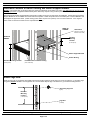
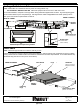
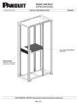
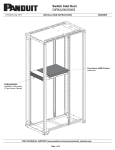
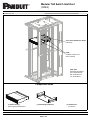
Modular ToR Switch Inlet Duct
(CDE2)
INSTRUCTIONS CM429A
© Panduit Corp. 2010
Cisco Nexus 2000 Series Switch
(reference)
CDE2
(installed in Net-Access
Server Cabinet)
TOOL LIST
#2 Philliips Screwdriver
5/16” Socket Wrench
3/8” Socket Wrench
1/4” Socket Driver
Component Guide
(1) Switch Ducting
(with hinged Perforated Door)
(1) Switch Support Bracket
(1) Hardware Kit
(not shown)
FOR TECHNICAL SUPPORT www.panduit.com/resources/install_maintain.asp
Page 1 of 4
INSTRUCTIONS CM429A
Determine Location of Switch Ducting and Switch Support Bracket
NOTES: Front to back span of equipment rails may need to be adjusted to accomodate your switch. See table below for front to rear rail
spacing requirements. Equipment installed directly below CDE2 may impede routing of switch power cord if installed prior to CDE2.
Switch Ducting and Switch Support Bracket components of CDE2 require two (2) rack spaces for installation. Switch Ducting and Switch
Support Bracket are to be installed at the same vertical rack position. CDE2 components are to be installed prior to switch installation and
are designed to support the switch. (CDE2 ducting system ONLY requires use of primary Cisco rack mount brackets. Cisco supplied
switch cradle or extension brackets are not compatible with CDE2.)
REAR OF
CABINET
1 RU Switch
(reference; port side of
switch faces Hot Aisle)
FRONT OF
CABINET
Intended
Mounting
Location
(2 rack spaces)
Switch Support Bracket
Switch Ducting
Intended Mounting Location
Perforated Door of Switch Ducting
(2 rack spaces)
(faces Cold Aisle)
Install Cage Nuts
Insert (2) cage nuts per equipment rail at CDE2 component mounting locations (8 total cage nuts are to be installed). (1) grounding cage
nut (green) must be installed in each equipment rail. The view below depicts cage nut locations for (1) intended mounting location.
Grounding Cage Nut
(green)
Intended
Mounting
Location
(2 rack spaces)
Cage Nut
(installed)
For Technical Support: www.panduit.com/resources/install_maintain.asp
Page 2 of 4
INSTRUCTIONS CM429A
Install Switch Ducting
Position Switch Ducting so that the perforated door of ducting faces the cold aisle and the mounting holes of Switch Ducting align with
cage nuts in equipment rails (installed on page 2). Secure Switch Ducting to equipment rails using (1) #12-24 Phillips screw and (1) hex
head grounding screw (green; use 5/16” socket wrench) per rail. Ensure that hex head grounding screws fasten into grounding cage nuts.
Switch Ducting
Perforated Door of Switch Ducting
Grounding Cage Nuts
(faces Cold Aisle)
(green)
(2) #12-24 Hex Head
Grounding Screws
(use 5/16” socket wrench)
(2) #12-24 Phillips Screws
FRONT OF
CABINET
Cage Nuts
(installed)
Install Switch Support Bracket
Position Switch Support Bracket so that the mounting holes of Switch Support Bracket align with cage nuts in equipment rails (installed on
page 2). Secure Switch Support Bracket to equipment rails using (1) #12-24 Phillips screw and (1) hex head grounding screw (green; use
5/16” socket wrench) per rail. Ensure that hex head grounding screws fasten into grounding cage nuts.
Grounding Cage Nuts
(2) #12-24 Hex Head
Grounding Screws
Switch Support
Bracket
(use 5/16” socket wrench)
(green)
REAR OF
CABINET
FRONT OF
CABINET
(2) #12-24 Phillips Screws
Cage Nuts
(installed)
For Technical Support: www.panduit.com/resources/install_maintain.asp
Page 3 of 4
INSTRUCTIONS CM429A
Routing of Switch Power Cable
NOTE: Dashed outline of 1 RU Switch is shown for power cord routing reference only.
DO NOT INSTALL SWITCH AT THIS TIME. Cabinet and equipment rails are not shown to add clarity to view.
Prior to switch installation, route power cord through Switch Ducting and Switch Support Bracket as shown. Slit grommet(s) along guide
lines as needed to allow for power cord pass-through. Use bridge features on Switch Support Bracket as tie-down point(s) to secure
switch power cord to Switch Support Bracket with cable tie.
REAR OF CABINET
FRONT OF CABINET
Switch
Support
Bracket
Switch Ducting
Switch Power Cord
(to rear-mounted power
outlet unit)
Bridge Feature
(use as tie-down
point for cable tie)
Slit Grommet(s) along guide lines as needed
to allow for power cord pass-through
Switch Power Cord
Install Switch
NOTE: Cabinet and equipment rails are not shown to add clarity to view.
Slide the 1 RU Switch onto positioning flanges of Switch Support Bracket. Carefully insert inlet side of switch into rear opening of Switch
Ducting. Position holes of 1 RU Switch rack mount brackets over threaded studs of Switch Support Bracket. Secure switch to Switch Support Bracket with (4) #10-32 acorn nuts (use 3/8” socket wrench).
Rear Opening of
Switch Ducting
FRONT OF CABINET
Positioning
Flange
1 RU Switch
(reference; port side of
switch faces Hot Aisle)
REAR OF
CABINET
Positioning
Flange
(4) #10-32 Acorn Nuts
(use 3/8” socket wrench)
For Instructions in Local Languages
and Technical Support:
www.panduit.com/resources/install_maintain.asp
www.panduit.com
Page 4 of 4
E-mail:
[email protected]
Fax:
(708)444-6448