1
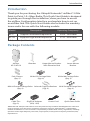
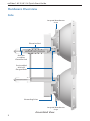
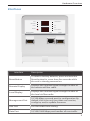
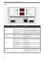
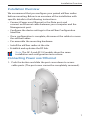
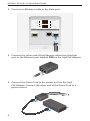
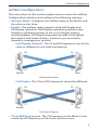
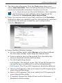
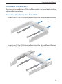
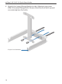
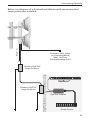
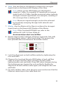
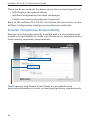
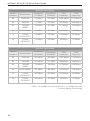
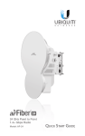
5 GHz Point to Point
1.0+ Gbps Radio
Model: AF-5, AF-5U
Introduction
Introduction
Thank you for purchasing the Ubiquiti Networks® airFiber® 5 GHz
Point-to-Point 1.0+ Gbps Radio. This Quick Start Guide is designed
to guide you through the installation, show you how to access
the airFiber Configuration Interface, and explain how to set up
an airFiber link. This Quick Start Guide also includes the warranty
terms and is for use with the following models:
Model
Description
Operating Frequency*
AF-5
Supports mid-band frequencies
5470 - 5950 MHz
AF-5U
Supports high-band frequencies
5725 - 6200 MHz
* Refer to the Specifications section for more information.
Package Contents
airFiber
AF-5/AF-5U
Pole Clamps
(Qty. 2)
I-Bracket
Upper Mount Bracket
with Elevation Rod
M10x150 Carriage Bolts
(Qty. 4)
M10x100 Carriage Bolts
(Qty. 2)
M8x14 Serrated Flange Bolts Azimuth Support Brackets
(Qty. 4)
(Qty. 2)
Cable Ties
(Qty. 2)
GigE PoE Adapter
(50V, 1.2A)
Lower Mount
Bracket
Power Cord
M10 Serrated Flange Nuts
(Qty. 6)
Quick Start Guide
TERMS OF USE: Ubiquiti radio devices must be professionally installed. Shielded Ethernet cable and
earth grounding must be used as conditions of product warranty. TOUGHCable™ is designed for
outdoor installations. It is the customer’s responsibility to follow local country regulations, including
operation within legal frequency channels, output power, and Dynamic Frequency Selection (DFS)
requirements.
1
airFiber® AF-5/AF-5U Quick Start Guide
Hardware Overview
Side
Lanyard Attachment
Loop
Elevation Rod
Hex Nut
to adjust
Elevation Rod
Pre-Installed
M10 x25
Flanged Bolts
Grounding Point
Lanyard Attachment
Loop
Assembled View
2
Hardware Overview
Interfaces
GPS
OVERLOAD
MASTER
LINK
8X
REMOTE
6X
RESET
MANAGEMENT
ACT
Interface
SPEED
4X TO 0.25X
LOCAL
AUX
DATA
ACT
SPEED
Description
Reset Button
To reset to factory defaults, press and hold the
Reset button for more than five seconds while
the unit is already powered on.
Remote Display
Displays the received signal strength in dBm of
the remote airFiber radio.
Local Display
Displays the received signal strength in dBm of
the local airFiber radio.
Management Port
10/100 Mbps, secured port for configuration. By
default, this is the only port that can monitor,
configure, and/or update firmware.
Aux Port
Port for audio tone aiming.
Data Port
10/100/1000 Mbps port handles all user traffic.
3
airFiber® AF-5/AF-5U Quick Start Guide
LEDs
GPS
OVERLOAD
MASTER
LINK
8X
REMOTE
6X
RESET
MANAGEMENT
ACT
LED
GPS
Master
Link
Remote
4
4X to 0.25X
LOCAL
AUX
SPEED
DATA
ACT
SPEED
State
Status
Off
No GPS Synchronization
On
Operational (Strong Signal)
Normal Flash*
Non-Operational (Weak Signal)
Off
Slave mode
On
Master mode
Off
RF Off
Short Flash*
Syncing
Normal Flash*
Beaconing
Long Flash*
Registering
On
Operational
On
Displays the received signal
strength in dBm of the remote
airFiber radio.
Hardware Overview
LED
State
Status
Local
On
Displays the received signal
strength in dBm of the local
airFiber radio.
Overload
Fast Flash
Overload Condition
(reserved)
–
–
8x
On
256QAM MIMO
6x
On
64QAM MIMO
On
16QAM MIMO
Long Flash*
QPSK MIMO
Normal Flash*
1x QPSK xRT™**
Short Flash*
¼x QPSK xRT**
4x to 0.25x
* Short Flash (1:3 on/off cycle)
Normal Flash (1:1 on/off cycle)
Long Flash (3:1 on/off cycle)
**xtreme Range Technology
Port LEDs
LED
Management
Act
Speed
Data
Act
Speed
State
Status
Off
No Ethernet Link
On
Ethernet Link Established
Random Flashing
Ethernet Activity
Off
10 Mbps
On
100 Mbps
Off
No Ethernet Link
On
Ethernet Link Established
Random Flashing
Ethernet Activity
Off
10/100 Mbps
On
1000 Mbps
5
airFiber® AF-5/AF-5U Quick Start Guide
Installation Requirements
Pre-Assembly Tool
• 13 mm wrench
Pole-Mounting Tool
• 17 mm wrench
Other Requirements
• Clear line of sight between airFiber radios
• Clear view of the sky for proper GPS operation
• Vertical mounting orientation
• Mounting location with < 0.5° displacement due to twist and
sway under wind loading
• Mounting point:
• At least 1 m below the highest point on the structure
• For tower installations, at least 3 m below the top of the tower
• Ground wires – min. 10 AWG (5 mm2) and max. length: 1 m.
As a safety precaution, ground the airFiber radios to grounded
masts, poles, towers, or grounding bars.
WARNING: Failure to properly ground your airFiber
units will void your warranty.
• (Recommended) 2 Outdoor GigE PoE surge protectors
Note: For guidelines about grounding and lightning
protection, follow your local electrical regulatory codes.
• Outdoor, shielded Category 6 (or above) cabling and
shielded RJ-45 connectors are required for all wired Ethernet
connections.
6
Installation Overview
Installation Overview
We recommend that you configure your paired airFiber radios
before mounting. Below is an overview of the installation with
specific details in the following instructions:
• Connect Power over Ethernet to the Data port, and
connect an Ethernet cable between your computer and the
Management port.
• Configure the device settings in the airFiber Configuration
Interface.
• Once configuration is complete, disconnect the cables to move
the airFiber radios.
• Pre-assemble the mounting hardware.
• Install the airFiber radios at the site.
• Establish and optimize the RF link.
Note: The AF-5 and AF-5U models share the same
installation and configuration instructions.
Connecting Power over Ethernet
1. Push the button and slide the port cover down to access
cable ports. (The port cover cannot be completely removed.)
7
airFiber® AF-5/AF-5U Quick Start Guide
2. Connect an Ethernet cable to the Data port.
OVERLOAD
GPS
MASTER
LINK
8X
REMOTE
6X
RESET
MANAGEMENT
ACT
SPEED
4X to 0.25X
LOCAL
AUX
DATA
ACT
SPEED
3. Connect the other end of the Ethernet cable from the Data
port to the Ethernet port labeled POE on the GigE PoE Adapter.
4. Connect the Power Cord to the power port on the GigE
PoE Adapter. Connect the other end of the Power Cord to a
power source.
8
airFiber Configuration
airFiber Configuration
The instructions in this section explain how to access the airFiber
Configuration Interface and configure the following settings:
• Wireless Mode Configure one airFiber radio as the Master and
the other as the Slave.
• Duplex The airFiber radio supports both half-duplex and
full‑duplex operation. Half-duplex operation provides more
frequency planning options at the cost of higher latency
and throughput. Full-duplex operation provides the highest
throughput and lowest latency; however, you have fewer
frequency management options.
-- Half Duplex (default) The TX and RX Frequencies can be the
same or different to suit local interference.
RX
RX
ncy A
e
Frequ
Frequ
e
ncy A
TX
TX
Master
Slave
Half-Duplex Diagram
-- Full Duplex The TX and RX Frequencies should be different.
RX
RX
ncy A
e
Frequ
Frequ
e
TX
ncy B
TX
Master
Slave
Full-Duplex Diagram
• TX and RX Frequencies The TX Frequency on the Master must
match the RX Frequency on the Slave, and vice versa.
9
airFiber® AF-5/AF-5U Quick Start Guide
1. Connect an Ethernet cable from your computer to the
Management port on the airFiber radio.
GPS
OVERLOAD
MASTER
LINK
8X
REMOTE
6X
RESET
MANAGEMENT
ACT
SPEED
4X to 0.25X
LOCAL
AUX
DATA
ACT
SPEED
2. Configure the Ethernet adapter on your computer with a static
IP address on the 192.168.1.x subnet.
3. Launch your web browser. Type http://192.168.1.20 in the
address field and press enter (PC) or return (Mac).
4. The login screen will appear. Enter ubnt in the Username and
Password fields. Select your Country and Language. You must
agree to the Terms of Use to use the product. Click Login.
Note: U.S. product versions are locked to the U.S. Country
Code to ensure compliance with FCC regulations.
10
airFiber Configuration
5. The Main tab will appear. Click the Tools drop-down and
select Link Calculator. This tool will guide you on how to best
minimize bandwidth and power/interference issues.
Note: If you do not see the Link Calculator, then upgrade
the firmware on your airFiber radios. Download the
firmware at: downloads.ubnt.com/airfiber
6. Enter the requirements of your link, and then click Calculate.
Adjust the values as needed to get the optimal result, and then
write down the settings needed for your configuration.
7. Click the Wireless tab.
8. Enter the Basic Wireless Settings:
a. For one airFiber radio, select Master as the Wireless Mode.
For the other airFiber radio, keep the default, Slave.
b. Enter a name in the Link Name field. This should be the
same on both the Master and the Slave.
c. For the Duplex drop-down:
-- Half Duplex The default mode. The TX and RX Frequencies
can be the same or different to suit local interference.
-- Full Duplex The TX and RX Frequencies should be different.
d. Select a TX Frequency. This must match the RX Frequency on
your other airFiber radio.
e. Select a RX Frequency. This must match the TX Frequency of
your other airFiber radio.
f. If needed, change the Output Power and/or Maximum
Modulation Rate settings.
11
airFiber® AF-5/AF-5U Quick Start Guide
9. Configure the Wireless Security:
a. Select the AES Key Type, HEX or ASCII.
b. For the Key field:
-- HEX Enter 16 bytes (eight, 16-bit HEX values: 0-9, A-F, or
a-f ). You can omit zeroes and use colons, similar to the
IPv6 format.
Note: The airFiber Configuration Interface supports
IPv6 formats excluding dotted quad and "::"
(double‑colon) notation.
-- ASCII Enter a combination of alphanumeric characters (0-9,
A-Z, or a-z).
10.Click Change and then click Apply.
11.In-Band Management is enabled by default, so each airFiber
radio must have a unique IP Address. (If the airFiber radios use
the same IP Address, then you may lose access to the airFiber
radios via the Data ports.) Click the Network tab.
a. For the Management IP Address option:
-- DHCP Keep the default, DHCP, to use DHCP reservation on
your router to assign a unique IP Address.
-- Static Change the IP Address, Netmask, and other settings
to make them compatible with your network.
b. Click Change and then click Apply.
Repeat the instructions in the airFiber Configuration section on
your other airFiber radio. After you have configured the airFiber
radios, disconnect them and move them to your installation site.
12
Hardware Installation
Hardware Installation
The mounting hardware of the airFiber radio can be pre‑assembled
before pole-mounting.
Mounting Hardware Pre-Assembly
1. Insert two M10x150 Carriage Bolts into the Lower Mount Bracket.
2. Insert two M10x150 Carriage Bolts into the Upper Mount Bracket
with Elevation Rod.
13
airFiber® AF-5/AF-5U Quick Start Guide
3. Attach the Lower Mount Bracket to the I-Bracket using two
M8x14 Serrated Flange Bolts. Ensure that the slots face up and
securely tighten the bolts.
Proper slot orientation
14
Hardware Installation
4. Attach the Upper Mount Bracket with Elevation Rod to the
I-Bracket using two M8x14 Serrated Flange Bolts.
Note: Ensure that the orientation of the Upper Mount
Bracket matches the illustration below, with the
Elevation Rod on the correct side.
15
airFiber® AF-5/AF-5U Quick Start Guide
5. Attach the Pole Clamps to the Mount Brackets.
a. Slide the slotted hole of each Pole Clamp over one upper
and one lower M10x150 Carriage Bolt.
b. Place one M10 Serrated Flange Nut on each M10x150
Carriage Bolt.
16
Hardware Installation
6. Attach the Azimuth Support Brackets together.
a. Insert the two M10x100 Carriage Bolts into the Azimuth
Support Bracket that has two slotted holes.
b. Slide the slotted hole of the other Azimuth Support Bracket
over one M10x100 Carriage Bolt.
c. Place one M10 Serrated Flange Nut on each M10x100
Carriage Bolt.
7. Check the four Pre-Installed M10x25 Flanged Bolts to ensure that
there is a 13 mm gap between each bolt head and its trunnion.
13 mm
13 mm
17
airFiber® AF-5/AF-5U Quick Start Guide
Pole-Mounting
1. Attach the Azimuth Support Brackets to the pole just beneath
the area where the airFiber radio will be attached.
Note: The mounting assembly can accommodate a
Ø 38.1 - 101.6 mm (1.5" - 4.0") pole.
a. Orient the Azimuth Support Brackets around the pole so it is
aimed in the direction of the other airFiber radio.
b. Slide the open slot of the Azimuth Support Bracket over the
corresponding M10x100 Carriage Bolt.
c. Tighten the M10 Serrated Flange Nuts to approximately
50 N-m.
18
Hardware Installation
2. Attach the mounting assembly to a pole.
a. Orient the mounting assembly around the pole so it is
aimed in the direction of the other airFiber radio.
b. Slide the open slot of each Pole Clamp over the
corresponding M10x150 Carriage Bolt.
c. Tighten the M10 Serrated Flange Nuts of the M10x150
Carriage Bolts to secure the mounting assembly to the pole.
19
airFiber® AF-5/AF-5U Quick Start Guide
3. Lift the airFiber radio and align the two lower Pre-Installed
M10x25 Flanged Bolts with the slots on the Lower Mount
Bracket. Seat the bolts in the slots.
20
Hardware Installation
4. Align the two upper Pre-Installed M10x25 Flanged Bolts of the
airFiber radio next to the slots on the Upper Mount Bracket. Lift
the airFiber radio and seat the bolts in the slots.
21
airFiber® AF-5/AF-5U Quick Start Guide
5. Attach a ground wire:
a. Remove the nut from the Grounding Point.
b. Attach a ground wire (min. 8 AWG or 10 mm2) to the lug and
replace the nut to secure the wire.
c. Secure the other end of the ground wire to a grounded
mast, pole, tower, or grounding bar.
WARNING: Failure to properly ground your airFiber
units will void your warranty.
Note: The ground wire should be as short as possible
and no longer than one meter in length.
22
Connecting Ethernet
Connecting Ethernet
1. Push the button and slide the port cover down to access
cable ports. (The port cover cannot be completely removed.)
2. Connect the Data/PoE Ethernet cable:
a. Feed an outdoor, shielded CAT6 cable up through the
rightmost cable feed slot on the bottom of the port cover.
b. Connect the cable to the Data port.
c. Create a strain relief for the Ethernet cable by feeding a
Cable Tie through the tie slot to the side of the cable.
d. Wrap the Cable Tie around the cable and tighten.
GPS
OVERLOAD
MASTER
LINK
8X
REMOTE
6X
RESET
MANAGEMENT
ACT
SPEED
4X to 0.25X
LOCAL
AUX
DATA
ACT
SPEED
23
airFiber® AF-5/AF-5U Quick Start Guide
3. Connect the other end of the Ethernet cable from the Data
port to the Ethernet port labeled POE on the GigE PoE Adapter.
4. Connect an Ethernet cable from your network to the Ethernet
port labeled LAN on the GigE PoE Adapter.
5. Connect the Power Cord to the power port on the GigE PoE
Adapter. Connect the other end of the Power Cord to a power
source.
Note: For added protection, we recommend installing two
GigE PoE surge protectors. Install the first surge protector
within 1 m of the airFiber Data port, and install the second
surge protector at the ingress point of the location housing
the wired network equipment.
24
Connecting Ethernet
Max. 1 m
Below is a diagram of a finished installation with recommended
surge protectors installed.
Ground to Pole, Tower,
or Grounding Block:
Max. 1 m from
Ground Bonding Point
Outdoor GigE PoE
Surge Protector
Outdoor GigE PoE
Surge Protector
GigE PoE Adapter
Power Source
25
airFiber® AF-5/AF-5U Quick Start Guide
Alignment
Tips
• To accurately align the airFiber radios for best performance, you
MUST align only one end of the link at a time.
• For more convenient alignment, you may consider using
long‑range scopes (not included) temporarily attached to your
airFiber radios.
• You may need to use additional hardware to compensate for
issues such as the improper orientation of a mounting pole or
significant elevation differences between airFiber radios.
Before a link is established, the Master's LED Display looks like this:
• GPS and Master LEDs are solidly lit
Note: The GPS LED may not be lit if there is a weak GPS
signal. A GPS signal is not required for alignment.
• Link Status LED flashes (Normal Flash 1:1)
• Remote and Local LED Displays show a double dash
GPS
OVERLOAD
MASTER
LINK
8X
REMOTE
6X
RESET
MANAGEMENT
ACT
SPEED
4X to 0.25X
LOCAL
AUX
DATA
ACT
SPEED
Note: The Local LED Display may briefly flash a large number
(such as 95) when there is no link.
26
Alignment
Establishing a Link
Adjust the positions of the Master and the Slave to establish a link.
Note: The Master must be aimed first at the Slave because
the Slave does not transmit any RF signal until it detects
transmissions from the Master.
1. Ensure that the following bolts and nuts are loose:
• Four Pre-Installed M10x25 Flanged Bolts on the airFiber radio
(two on each side)
• Four M10 Hex Nuts used to lock the elevation alignment on
the Upper Mount Bracket (two on each side)
2. Ensure that the pole mount is snug yet the four M10 Serrated
Flange Nuts attaching the Pole Clamps are loose enough to
allow rotation around the pole for azimuth alignment.
27
airFiber® AF-5/AF-5U Quick Start Guide
3. Master Visually aim the Master at the Slave. To adjust the
Master's position:
a. Rotate the airFiber radio on the pole to align the azimuth.
b. Use the hex nut on the Elevation Rod to adjust the elevation.
Note: Do NOT make simultaneous adjustments on the
Master and Slave.
4. Slave Visually aim the Slave at the Master. To adjust the Slave's
position:
a. Rotate the airFiber radio on the pole to align the azimuth.
b. Use the hex nut on the Elevation Rod to adjust the elevation.
5. Check to see if a link is established. Ensure that the Link Status
LED is solidly lit green and the Remote and Local LED Displays of
the Slave are displaying signal levels.
GPS
OVERLOAD
MASTER
LINK
8X
REMOTE
6X
RESET
MANAGEMENT
ACT
28
SPEED
4X to 0.25X
LOCAL
AUX
DATA
ACT
SPEED
Alignment
6. Slave Aim the Slave at the Master to achieve the strongest
signal level on the Remote LED Display of the Slave.
Note: Values on the LED Displays are displayed in
negative (-) dBm. For example, 67 represents a received
signal level of -67 dBm. Smaller numerical values indicate
stronger received signal levels. For example, a reading of
49 is stronger than a reading of 55.
Note: Maximum signal strength can best be achieved
by iteratively sweeping through both azimuth and
elevation.
7. Master Aim the Master at the Slave to achieve the strongest
signal level on the Remote LED Display of the Master.
Note: If the Overload LED lights up, refer to the
airFiber AF-5/AF-5U User Guide at:
documentation.ubnt.com/airfiber
8. Repeat steps 6 and 7 until you achieve a symmetric link, with
the signal levels within 1 dB of each other. This ensures the
best possible data rate between the airFiber radios.
GPS
OVERLOAD
MASTER
LINK
8X
REMOTE
6X
RESET
MANAGEMENT
ACT
SPEED
4X to 0.25X
LOCAL
AUX
DATA
ACT
SPEED
9. Lock the alignment on both airFiber radios by tightening the
nuts and bolts.
10.Observe the Local and Remote LED Displays of each airFiber
radio to ensure that the values remains constant while
tightening the nuts and bolts. If any LED value changes during
the locking process, loosen the nuts and bolts, finalize the
alignment of each airFiber radio again, and retighten the nuts
and bolts.
11.For each airFiber radio, close the port cover and ensure that the
Ethernet cable stays in the cable feed slot.
29
airFiber® AF-5/AF-5U Quick Start Guide
There are three methods for determining the received signal level:
• LED Displays (described above)
• airFiber Configuration Interface (webpage)
• Audio tone (optional equipment required)
Refer to the airFiber AF-5/AF-5U User Guide for instructions on the
airFiber Configuration Interface and audio tone methods.
Installer Compliance Responsibility
Devices must be professionally installed and it is the professional
installer’s responsibility to make sure the device is operated within
local country regulatory requirements.
The Frequency and Output Power fields are provided to the
professional installer to assist in meeting regulatory requirements.
30
Specifications
Specifications
airFiber AF-5/AF-5U
Dimensions
Weight
Mount Not Included
Mount Included
Operating Frequency
AF-5
FCC 15.247, 15.407, IC RSS 210
ETSI EN 301 893, EN 302 502
Other Regions
AF-5U
FCC 15.247, IC RSS 21
ETSI EN 302 502
Other Regions
Max Power Consumption
938.4 x 468.4 x 281.4 mm
(36.94 x 18.44 x 11.08 in)
11.5 kg (25.35 lb)
16 kg (35.27 lb)
5470 - 5600 MHz, 5650 - 5850 MHz
5470 - 5875 MHz
5470 - 5950 MHz
5725 - 5850 MHz
5725 - 5875 MHz
5725 - 6200 MHz
40 W
Power Supply
50V, 1.2A PoE GigE Adapter
(Included)
Power Method
Passive Power over Ethernet
(42-58VDC)
Certifications
Mounting
Wind Loading
Wind Survivability
Operating Temperature
CE, FCC, IC
Pole Mount Kit (Included)
863 N @ 200 km/hr
(194 lbf @ 125 mph)
200 km/hr (125 mph)
-40 to 55° C (-40 to 131°F)
Networking Interface
Data Port
Management Port
(1) 10/100/1000 Ethernet Port
(1) 10/100 Ethernet Port
31
airFiber® AF-5/AF-5U Quick Start Guide
Receive Sensitivity
Spatial
Streams
Modulation
Sensitivity
(10 MHz)
Sensitivity
(20 MHz)
FDD
Capacity*
TDD
Capacity*
8x
256QAM
-70 dBm
-67 dBm
1024 Mbps
512 Mbps
6x
64QAM
-77 dBm
-74 dBm
768 Mbps
384 Mbps
4x
16QAM
MIMO
-84 dBm
-81 dBm
512 Mbps
256 Mbps
2x
QPSK MIMO
-90 dBm
-87 dBm
256 Mbps
128 Mbps
1x
½ Rate
QPSK xRT**
-93 dBm
-90 dBm
128 Mbps
64 Mbps
¼x
¼ Rate
QPSK xRT
-95 dBm
-93 dBm
32 Mbps
16 Mbps
Receive Sensitivity
Spatial
Streams
Modulation
Sensitivity
(40 MHz)
Sensitivity
(50 MHz)
FDD
Capacity*
TDD
Capacity*
8x
256QAM
-65 dBm
-64 dBm
1024 Mbps
512 Mbps
6x
64QAM
-72 dBm
-71 dBm
768 Mbps
384 Mbps
4x
16QAM
MIMO
-79 dBm
-78 dBm
512 Mbps
256 Mbps
2x
QPSK MIMO
-85 dBm
-84 dBm
256 Mbps
128 Mbps
1x
½ Rate
QPSK xRT**
-88 dBm
-87 dBm
128 Mbps
64 Mbps
¼x
¼ Rate
QPSK xRT
-92 dBm
-91 dBm
32 Mbps
16 Mbps
* FDD = (2) 50 MHz channels and TDD = (1) 50 MHz channel
**xtreme Range Technology
32
Safety Notices
Safety Notices
1. Read, follow, and keep these instructions.
2. Heed all warnings.
3. Only use attachments/accessories specified by the manufacturer.
WARNING: Do not use this product in location that can be
submerged by water.
WARNING: Avoid using this product during an electrical storm.
There may be a remote risk of electric shock from lightning.
Electrical Safety Information
1. Compliance is required with respect to voltage, frequency, and current
requirements indicated on the manufacturer’s label. Connection to a
different power source than those specified may result in improper
operation, damage to the equipment or pose a fire hazard if the
limitations are not followed.
2. There are no operator serviceable parts inside this equipment. Service
should be provided only by a qualified service technician.
3. This equipment is provided with a detachable power cord which has an
integral safety ground wire intended for connection to a grounded safety
outlet.
a. Do not substitute the power cord with one that is not the provided
approved type. Never use an adapter plug to connect to a 2-wire
outlet as this will defeat the continuity of the grounding wire.
b. The equipment requires the use of the ground wire as a part of the
safety certification, modification or misuse can provide a shock
hazard that can result in serious injury or death.
c. Contact a qualified electrician or the manufacturer if there are
questions about the installation prior to connecting the equipment.
d. Protective earthing is provided by Listed AC adapter. Building
installation shall provide appropriate short-circuit backup protection.
e. Protective bonding must be installed in accordance with local
national wiring rules and regulations.
33
airFiber® AF-5/AF-5U Quick Start Guide
Limited Warranty
UBIQUITI NETWORKS, Inc (“UBIQUITI NETWORKS”) warrants that the
product(s) furnished hereunder (the “Product(s)”) shall be free from defects
in material and workmanship for a period of one (1) year from the date of
shipment by UBIQUITI NETWORKS under normal use and operation. UBIQUITI
NETWORKS’ sole and exclusive obligation and liability under the foregoing
warranty shall be for UBIQUITI NETWORKS, at its discretion, to repair or
replace any Product that fails to conform to the above warranty during the
above warranty period. The expense of removal and reinstallation of any
Product is not included in this warranty. The warranty period of any repaired
or replaced Product shall not extend beyond its original term.
Warranty Conditions
The above warranty does not apply if the Product:
(I) has been modified and/or altered, or an addition made thereto, except
by Ubiquiti Networks, or Ubiquiti Networks’ authorized representatives,
or as approved by Ubiquiti Networks in writing;
(II) has been painted, rebranded or physically modified in any way;
(III) has been damaged due to errors or defects in cabling;
(IV) has been subjected to misuse, abuse, negligence, abnormal physical,
electromagnetic or electrical stress, including lightning strikes, or
accident;
(V) has been damaged or impaired as a result of using third party firmware;
(VI) has no original Ubiquiti MAC label, or is missing any other original
Ubiquiti label(s); or
(VII) has not been received by Ubiquiti within 30 days of issuance of the
RMA.
In addition, the above warranty shall apply only if: the product has been
properly installed and used at all times in accordance, and in all material
respects, with the applicable Product documentation; all Ethernet cabling
runs use CAT5 (or above), and for outdoor installations, shielded Ethernet
cabling is used, and for indoor installations, indoor cabling requirements are
followed.
WARNING: Failure to properly ground your airFiber units
will void your warranty. (Please follow the instructions on
page 22 for installation of the ground wires.)
Returns
No Products will be accepted for replacement or repair without obtaining
a Return Materials Authorization (RMA) number from UBIQUITI NETWORKS
during the warranty period, and the Products being received at UBIQUITI
NETWORKS’ facility freight prepaid in accordance with the RMA process of
UBIQUITI NETWORKS. Products returned without an RMA number will not
be processed and will be returned freight collect or subject to disposal.
Information on the RMA process and obtaining an RMA number can be found
at: www.ubnt.com/support/warranty.
34
Limited Warranty
Disclaimer
EXCEPT FOR ANY EXPRESS WARRANTIES PROVIDED HEREIN, UBIQUITI
NETWORKS, ITS AFFILIATES, AND ITS AND THEIR THIRD PARTY Data, SERVICE,
SOFTWARE AND HARDWARE PROVIDERS HEREBY DISCLAIM AND MAKE NO
OTHER REPRESENTATION OR WARRANTY OF ANY KIND, EXPRESS, IMPLIED
OR STATUTORY, INCLUDING, BUT NOT LIMITED TO, REPRESENTATIONS,
GUARANTEES, OR WARRANTIES OF MERCHANTABILITY, ACCURACY, QUALITY
OF SERVICE OR RESULTS, AVAILABILITY, SATISFACTORY QUALITY, LACK
OF VIRUSES, QUIET ENJOYMENT, FITNESS FOR A PARTICULAR PURPOSE
AND NON-INFRINGEMENT AND ANY WARRANTIES ARISING FROM ANY
COURSE OF DEALING, USAGE OR TRADE PRACTICE IN CONNECTION WITH
SUCH PRODUCTS AND SERVICES. BUYER ACKNOWLEDGES THAT NEITHER
UBIQUITI NETWORKS NOR ITS THIRD PARTY PROVIDERS CONTROL BUYER’S
EQUIPMENT OR THE TRANSFER OF Data OVER COMMUNICATIONS FACILITIES,
INCLUDING THE INTERNET, AND THAT THE PRODUCTS AND SERVICES MAY
BE SUBJECT TO LIMITATIONS, INTERRUPTIONS, DELAYS, CANCELLATIONS
AND OTHER PROBLEMS INHERENT IN THE USE OF COMMUNICATIONS
FACILITIES. UBIQUITI NETWORKS, ITS AFFILIATES AND ITS AND THEIR THIRD
PARTY PROVIDERS ARE NOT RESPONSIBLE FOR ANY INTERRUPTIONS,
DELAYS, CANCELLATIONS, DELIVERY FAILURES, Data LOSS, CONTENT
CORRUPTION, PACKET LOSS, OR OTHER DAMAGE RESULTING FROM ANY
OF THE FOREGOING. In addition, UBIQUITI NETWORKS does not warrant
that the operation of the Products will be error-free or that operation will
be uninterrupted. In no event shall UBIQUITI NETWORKS be responsible
for damages or claims of any nature or description relating to system
performance, including coverage, buyer’s selection of products (including
the Products) for buyer’s application and/or failure of products (including the
Products) to meet government or regulatory requirements.
Limitation of Liability
EXCEPT TO THE EXTENT PROHIBITED BY LOCAL LAW, IN NO EVENT WILL
UBIQUITI OR ITS SUBSIDIARIES, AFFILIATES OR SUPPLIERS BE LIABLE FOR
DIRECT, SPECIAL, INCIDENTAL, CONSEQUENTIAL OR OTHER DAMAGES
(INCLUDING LOST PROFIT, LOST Data, OR DOWNTIME COSTS), ARISING OUT
OF THE USE, INABILITY TO USE, OR THE RESULTS OF USE OF THE PRODUCT,
WHETHER BASED IN WARRANTY, CONTRACT, TORT OR OTHER LEGAL THEORY,
AND WHETHER OR NOT ADVISED OF THE POSSIBILITY OF SUCH DAMAGES.
Note
Some countries, states and provinces do not allow exclusions of implied
warranties or conditions, so the above exclusion may not apply to you. You
may have other rights that vary from country to country, state to state, or
province to province. Some countries, states and provinces do not allow the
exclusion or limitation of liability for incidental or consequential damages, so
the above limitation may not apply to you. EXCEPT TO THE EXTENT ALLOWED
BY LOCAL LAW, THESE WARRANTY TERMS DO NOT EXCLUDE, RESTRICT OR
MODIFY, AND ARE IN ADDITION TO, THE MANDATORY STATUTORY RIGHTS
APPLICABLE TO THE LICENSE OF ANY SOFTWARE (EMBEDDED IN THE
PRODUCT) TO YOU. The United Nations Convention on Contracts for the
International Sale of Goods shall not apply to any transactions regarding the
sale of the Products.
35
airFiber® AF-5/AF-5U Quick Start Guide
Compliance
FCC
Changes or modifications not expressly approved by the party responsible
for compliance could void the user’s authority to operate the equipment.
This device complies with Part 15 of the FCC Rules. Operation is subject to the
following two conditions:
1. This device may not cause harmful interference, and
2. This device must accept any interference received, including interference
that may cause undesired operation.
NOTE: This equipment has been tested and found to comply with the limits
for a Class B digital device, pursuant to part 15 of the FCC Rules. These limits
are designed to provide reasonable protection against harmful interference
when the equipment is operated in a commercial environment. This
equipment generates, uses, and can radiate radio frequency energy and, if
not installed and used in accordance with the instruction manual, may cause
harmful interference to radio communications. Operations of this equipment
in a residential area is likely to cause harmful interference in which case the
user will be required to correct the interference at his own expense.
Industry Canada
CAN ICES-3(B)/NMB-3(B)
To reduce potential radio interference to other users, the antenna type and
its gain should be so chosen that the equivalent isotropically radiated power
(e.i.r.p.) is not more than that permitted for successful communication.
This device complies with Industry Canada licence-exempt RSS standard(s).
Operation is subject to the following two conditions:
1. This device may not cause interference, and
2. This device must accept any interference, including interference that may
cause undesired operation of the device.
CAN ICES-3(B)/NMB-3(B)
Pour réduire le risque d’interférence aux autres utilisateurs, le type d’antenne
et son gain doivent être choisies de façon que la puissance isotrope
rayonnée équivalente (PIRE) ne dépasse pas ce qui est nécessaire pour une
communication réussie.
Cet appareil est conforme à la norme RSS Industrie Canada exempts de
licence norme(s). Son fonctionnement est soumis aux deux conditions
suivantes:
1. Cet appareil ne peut pas provoquer d’interférences et
2. Cet appareil doit accepter toute interférence, y compris les interférences
qui peuvent causer un mauvais fonctionnement du dispositif.
36
Compliance
RF Exposure Warning
The antennas used for this transmitter must be installed to provide a
separation distance of at least 126 cm (AF-5) or 123 cm (AF-5U) from all
persons and must not be located or operating in conjunction with any other
antenna or transmitter.
Les antennes utilisées pour ce transmetteur doivent être installé en
considérant une distance de séparation de toute personnes d’au moins
126 cm (AF-5) ou 123 cm (AF-5U) et ne doivent pas être localisé ou utilisé en
conflit avec tout autre antenne ou transmetteur.
Australia and New Zealand
Warning: This is a Class B product. In a domestic environment this
product may cause radio interference in which case the user may be
required to take adequate measures.
CE Marking
CE marking on this product represents the product is in compliance with all
directives that are applicable to it.
Alert Sign (!) Follows CE Marking
Alert sign must be indicated if a restriction on use applied to the product and
it must follow the CE marking.
RoHS/WEEE Compliance Statement
English
European Directive 2002/96/EC requires that the equipment bearing this
symbol on the product and/or its packaging must not be disposed of with
unsorted municipal waste. The symbol indicates that this product should
be disposed of separately from regular household waste streams. It is your
responsibility to dispose of this and other electric and electronic equipment
via designated collection facilities appointed by the government or local
authorities. Correct disposal and recycling will help prevent potential
negative consequences to the environment and human health. For more
detailed information about the disposal of your old equipment, please
contact your local authorities, waste disposal service, or the shop where you
purchased the product.
37
airFiber® AF-5/AF-5U Quick Start Guide
Deutsch
Die Europäische Richtlinie 2002/96/EC verlangt, dass technische
Ausrüstung, die direkt am Gerät und/oder an der Verpackung mit diesem
Symbol versehen ist, nicht zusammen mit unsortiertem Gemeindeabfall
entsorgt werden darf. Das Symbol weist darauf hin, dass das Produkt von
regulärem Haushaltmüll getrennt entsorgt werden sollte. Es liegt in Ihrer
Verantwortung, dieses Gerät und andere elektrische und elektronische
Geräte über die dafür zuständigen und von der Regierung oder örtlichen
Behörden dazu bestimmten Sammelstellen zu entsorgen. Ordnungsgemäßes
Entsorgen und Recyceln trägt dazu bei, potentielle negative Folgen für
Umwelt und die menschliche Gesundheit zu vermeiden. Wenn Sie weitere
Informationen zur Entsorgung Ihrer Altgeräte benötigen, wenden Sie sich
bitte an die örtlichen Behörden oder städtischen Entsorgungsdienste oder an
den Händler, bei dem Sie das Produkt erworben haben.
Español
La Directiva 2002/96/CE de la UE exige que los equipos que lleven este
símbolo en el propio aparato y/o en su embalaje no deben eliminarse
junto con otros residuos urbanos no seleccionados. El símbolo indica
que el producto en cuestión debe separarse de los residuos domésticos
convencionales con vistas a su eliminación. Es responsabilidad suya
desechar este y cualesquiera otros aparatos eléctricos y electrónicos a
través de los puntos de recogida que ponen a su disposición el gobierno y
las autoridades locales. Al desechar y reciclar correctamente estos aparatos
estará contribuyendo a evitar posibles consecuencias negativas para el
medio ambiente y la salud de las personas. Si desea obtener información
más detallada sobre la eliminación segura de su aparato usado, consulte a las
autoridades locales, al servicio de recogida y eliminación de residuos de su
zona o pregunte en la tienda donde adquirió el producto.
Français
La directive européenne 2002/96/CE exige que l’équipement sur lequel
est apposé ce symbole sur le produit et/ou son emballage ne soit pas jeté
avec les autres ordures ménagères. Ce symbole indique que le produit doit
être éliminé dans un circuit distinct de celui pour les déchets des ménages.
Il est de votre responsabilité de jeter ce matériel ainsi que tout autre
matériel électrique ou électronique par les moyens de collecte indiqués
par le gouvernement et les pouvoirs publics des collectivités territoriales.
L’élimination et le recyclage en bonne et due forme ont pour but de lutter
contre l’impact néfaste potentiel de ce type de produits sur l’environnement
et la santé publique. Pour plus d’informations sur le mode d’élimination de
votre ancien équipement, veuillez prendre contact avec les pouvoirs publics
locaux, le service de traitement des déchets, ou l’endroit où vous avez acheté
le produit.
38
Declaration of Conformity
Italiano
La direttiva europea 2002/96/EC richiede che le apparecchiature
contrassegnate con questo simbolo sul prodotto e/o sull’imballaggio non
siano smaltite insieme ai rifiuti urbani non differenziati. Il simbolo indica
che questo prodotto non deve essere smaltito insieme ai normali rifiuti
domestici. È responsabilità del proprietario smaltire sia questi prodotti sia
le altre apparecchiature elettriche ed elettroniche mediante le specifiche
strutture di raccolta indicate dal governo o dagli enti pubblici locali. Il
corretto smaltimento ed il riciclaggio aiuteranno a prevenire conseguenze
potenzialmente negative per l’ambiente e per la salute dell’essere umano.
Per ricevere informazioni più dettagliate circa lo smaltimento delle vecchie
apparecchiature in Vostro possesso, Vi invitiamo a contattare gli enti pubblici
di competenza, il servizio di smaltimento rifiuti o il negozio nel quale avete
acquistato il prodotto.
Declaration of Conformity
Česky
[Czech]
UBIQUITI NETWORKS tímto prohla uje, e tento UBIQUITI
NETWORKS device, je ve shod se základními po adavky a dal ími p
íslu n mi ustanoveními sm rnice 1999/5/ES.
Dansk
[Danish]
Undertegnede UBIQUITI NETWORKS erklærer herved, at følgende
udstyr UBIQUITI NETWORKS device, overholder de væsentlige krav
og øvrige relevante krav i direktiv 1999/5/EF.
Nederlands
[Dutch]
Hierbij verklaart UBIQUITI NETWORKS dat het toestel UBIQUITI
NETWORKS device, in overeenstemming is met de essentiële eisen
en de andere relevante bepalingen van richtlijn 1999/5/EG.
Bij deze verklaart UBIQUITI NETWORKS dat deze UBIQUITI
NETWORKS device, voldoet aan de essentiële eisen en aan de
overige relevante bepalingen van Richtlijn 1999/5/EC.
English
Hereby, UBIQUITI NETWORKS, declares that this UBIQUITI
NETWORKS device, is in compliance with the essential requirements
and other relevant provisions of Directive 1999/5/EC.
Eesti
[Estonian]
Käesolevaga kinnitab UBIQUITI NETWORKS seadme UBIQUITI
NETWORKS device, vastavust direktiivi 1999/5/EÜ põhinõuetele ja
nimetatud direktiivist tulenevatele teistele asjakohastele sätetele.
Suomi
[Finnish]
UBIQUITI NETWORKS vakuuttaa täten että UBIQUITI NETWORKS
device, tyyppinen laite on direktiivin 1999/5/EY oleellisten
vaatimusten ja sitä koskevien direktiivin muiden ehtojen
mukainen.
Français
[French]
Par la présente UBIQUITI NETWORKS déclare que l’appareil
UBIQUITI NETWORKS, device est conforme aux exigences
essentielles et aux autres dispositions pertinentes de la directive
1999/5/CE.
Deutsch
[German]
Hiermit erklärt UBIQUITI NETWORKS, dass sich diese UBIQUITI
NETWORKS device, in Übereinstimmung mit den grundlegenden
Anforderungen und den anderen relevanten Vorschriften der
Richtlinie 1999/5/EG befindet. (BMWi)
39
airFiber® AF-5/AF-5U Quick Start Guide
Ελληνική
[Greek]
ΜΕ ΤΗΝ ΠΑΡΟΥΣΑ UBIQUITI NETWORKS ΔΗΛΩΝΕΙ ΟΤΙ UBIQUITI
NETWORKS device, ΣΥΜΜΟΡΦΩΝΕΤΑΙ ΠΡΟΣ ΤΙΣ ΟΥΣΙΩΔΕΙΣ
ΑΠΑΙΤΗΣΕΙΣ ΚΑΙ ΤΙΣ ΛΟΙΠΕΣ ΣΧΕΤΙΚΕΣ ΔΙΑΤΑΞΕΙΣ ΤΗΣ ΟΔΗΓΙΑΣ
1995/5/ΕΚ.
Magyar
[Hungarian]
Alulírott, UBIQUITI NETWORKS nyilatkozom, hogy a
UBIQUITI NETWORKS device, megfelel a vonatkozó alapvetõ
követelményeknek és az 1999/5/EC irányelv egyéb elõírásainak.
Íslenska
[Icelandic]
Hér me l sir UBIQUITI NETWORKS yfir ví a UBIQUITI NETWORKS
device, er í samræmi vi grunnkröfur og a rar kröfur, sem ger ar eru í
tilskipun 1999/5/EC.
Italiano
[Italian]
Con la presente UBIQUITI NETWORKS dichiara che questo UBIQUITI
NETWORKS device, è conforme ai requisiti essenziali ed alle altre
disposizioni pertinenti stabilite dalla direttiva 1999/5/CE.
Latviski
[Latvian]
Ar o UBIQUITI NETWORKS deklar , ka UBIQUITI NETWORKS device,
atbilst Direkt vas 1999/5/EK b tiskaj m pras b m un citiem ar to saist
tajiem noteikumiem.
Lietuviškai
[Lithuanian]
UBIQUITI NETWORKS deklaruoja, kad šis UBIQUITI NETWORKS
įrenginys atitinka esminius reikalavimus ir kitas 1999/5/EB
Direktyvos nuostatas.
Malti
[Maltese]
Hawnhekk, UBIQUITI NETWORKS, jiddikjara li dan UBIQUITI
NETWORKS device, jikkonforma mal- ti ijiet essenzjali u ma
provvedimenti o rajn relevanti li hemm fid-Dirrettiva 1999/5/EC.
Norsk
[Norwegian]
UBIQUITI NETWORKS erklærer herved at utstyret UBIQUITI
NETWORKS device, er i samsvar med de grunnleggende krav og
øvrige relevante krav i direktiv 1999/5/EF.
Slovensky
[Slovak]
UBIQUITI NETWORKS t mto vyhlasuje, e UBIQUITI NETWORKS
device, sp a základné po iadavky a v etky príslu né ustanovenia
Smernice 1999/5/ES.
Svenska
[Swedish]
Härmed intygar UBIQUITI NETWORKS att denna UBIQUITI
NETWORKS device, står I överensstämmelse med de väsentliga
egenskapskrav och övriga relevanta bestämmelser som framgår av
direktiv 1999/5/EG.
Español
[Spanish]
Por medio de la presente UBIQUITI NETWORKS declara que el
UBIQUITI NETWORKS device, cumple con los requisitos esenciales
y cualesquiera otras disposiciones aplicables o exigibles de la
Directiva 1999/5/CE.
Polski
[Polish]
Niniejszym, firma UBIQUITI NETWORKS o wiadcza, e produkt serii
UBIQUITI NETWORKS device, spełnia zasadnicze wymagania i inne
istotne postanowienia Dyrektywy 1999/5/EC.
Português
[Portuguese]
UBIQUITI NETWORKS declara que este UBIQUITI NETWORKS device,
está conforme com os requisitos essenciais e outras disposições da
Directiva 1999/5/CE.
Română
[Romanian]
Prin prezenta, UBIQUITI NETWORKS declară că acest dispozitiv
UBIQUITI NETWORKS este în conformitate cu cerințele esențiale și
alte prevederi relevante ale Directivei 1999/5/CE.
JL091514
40
www.ubnt.com
Support
support.ubnt.com
Community community.ubnt.com
Downloads downloads.ubnt.com
© 2013-2014 Ubiquiti Networks, Inc. All rights reserved. Ubiquiti, Ubiquiti Networks,
the Ubiquiti U logo, the Ubiquiti beam logo, airFiber, and TOUGHCable are trademarks
or registered trademarks of Ubiquiti Networks, Inc. in the United States and in other
countries. All other trademarks are the property of their respective owners.
*640-00097-05*
640-00097-05