Transcript
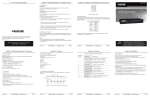
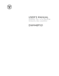
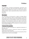
Chapter 5: IR Remote Control/Chapter 6: Serial Control
Chapter 4: Operation
Chapter 5: IR Remote Control/Chapter 6: Serial Control
4. Operation
5. IR Remote Control
LED Indicator
The remote control operates within a 1.5-ft. (5-m) range of the DVI switch. To select a source
device with a remote control, press the number button (1–8) to directly switch to the
corresponding port.
NOTES:
1. Remove the battery protector on the remote control before operation.
2. O
n the remote control, only buttons 1–8 are activated. The rest of the buttons are reserved for
other models.
The Power LED turns green when the video switch is powered on. When a video port is selected,
its corresponding Port LED turns yellow.
Push Button
Press the corresponding button to select a port.
EDID Setting
In some cases, display problems may occur because of incorrect Extended Display Identification
(EDID) communication between the display monitor and the unit. This function allows the
system either to read the necessary EDID information from the unit, or to copy EDID from
EDID-compliant displays.
Default Setting
To reset to the default EDID:
Step 1: Press and hold the “EDID Copy” button on the unit and release the button RIGHT AFTER
the Power LED flashes red (6–7 seconds).
Step 2: The LED lights steady red and green indicating that the EDID default setting is completed.
Copy (New) Monitor EDID
When using a monitor (EDID-compliant) for display, the unit’s EDID Copy function will enable
EDID communication between the monitor and the unit for optimal video quality. Follow these
steps:
© Copyright 2013. Black Box Corporation. All rights reserved. Black Box® and the Double Diamond
logo are registered trademarks of BB Technologies, Inc. Any third-party trademarks appearing in
this manual are acknowledged to be the property of their respective owners.
AVSW-DVI8X1, version 2
FREE! Live, 24/7 Tech Support is just 30 seconds away.
724-746-5500 | blackbox.com
3
6
7
8
9
10
11
12
13
13
Figure 5-1. Remote control.
6. Serial Control
The DVI and audio switches’ built in serial interface enables users to control the switch via a PC,
serial controller devices, or home theater system. The controller’s serial port should be configured
as shown in Table 6-1.
Table 6-1. Serial parameters settings.
8
None
Stop Bits
1
NOTE: If the Power LED flashes red, the reason could be:
1. The monitor is not connected.
2. The monitor is not powered on.
3. The EDID data of the monitor is not applicable.
Flow Control
None
8 x 1 DVI and Audio Switch (AVSW-DVI8X1s):
To select a source device via serial interface, select the number that corresponds to the port.
For example, send “1” to switch to Port 1.
AVSW-DVI4X1
724-746-5500 | blackbox.com
BLACK BOX
Serial Control Support —Yes
• Foot pad
User Controls — (1) EDID copy push button, (8) port selection buttons
• IR remote controller
Connectors — Input: (8) DVI (digital only), (8) audio jacks;
Output: (1) DVI (digital only), (1) audio jack
• Power supply and power cord
Indicators — (9) LEDs: (1) dual-color for Power and Video,
(8) LEDs for video input
Optional:
• This user manual
• Audio cable
Component
1
(8) Input LED indicators
2
(1) Power LED indicator
3
Figure 2-1 shows the front and back panels of the AVSW-DVI8X1. Table 2-1 describes its
components.
13 13
13
13 13
13
13 13
• Control via front-panel push buttons, IR remote control, or serial control.
8 X 1 DVI Switch with Auido
4
2
1
3
4
6
5
2
8
7
8
• HDTV compatible.
OUTPUT
• Protects content via HDCP.
• Before installation, power off all devices that will be connected to this system.
Description
• Make sure that all devices you will connect are properly grounded.
On Yellow when port 1–8 is selected.
Off when port 1–8 is not selected.
• Place cables away from fluorescent lights, air conditioners, and machines that are likely to
generate electrical noise.
On Green when power to the unit is on.
NOTE: If no screen displays, follow these steps:
Off when power to the unit is off.
1. Make sure the device cables are correctly and firmly attached.
(8) Push buttons
Press buttons 1–8 to select a port.
3. Check the PC BIOS configuration for the video output settings.
4
(1) Audio port (Output)
Connects to a speaker.
4. Connect your computer to the display DIRECTLY to check if the video signal gets through.
5
(8) Audio ports (Input)
Connect to audio sources 1–8.
1. Use a video cable (DVI) to connect the display to the video output port on the back of the
switch. Plug a set of audio jacks from the speaker to the switch’s speaker port.
6
(1) Video port (Output)
Connects to a display.
7
(8) Video ports (Input)
Connect to video sources 1–8.
2. Use a video cable (DVI) to connect the source device to the video input port on the switch.
Use an audio cable to connect the speaker port from the input side of the switch to the
corresponding output port on the source device.
8
EDID Copy button
Copy a monitor’s EDID.
9
Serial port
Connects to a computer for serial control.
10
Power supply
Applies power to the unit.
2. Set your display device’s input source as DVI.
Installation Steps
2.3 Hardware Description
• Select (1) DVI + Audio from (8) DVI + Audio sources.
Chapter 3: Installation
3. Installation
Number in
Fig. 2-1
• Rear bracket
• Screw kit
Page 6
Order toll-free in the U.S.: Call 877-877-BBOX (outside U.S.
call 724-746-5500) FREE technical support 24 hours a day, 7 days a
week: Call 724-746-5500 or fax 724-746-0746 Mailing address:
Black Box Corporation, 1000 Park Drive, Lawrence, PA 15055-1018
Web site: www.blackbox.com • E-mail: [email protected]
Table 2-1. 8X1 DVI and Audio switch components.
®
Remote Control Support — Yes
Customer
Support
Information
Chapter 2: Overview
• Video switch
• LED shows the active status of DVI + Audio sources.
16
Parity
2.2 What’s Included
• EDID Copy function ensures optimal screen resolution.
15
9600
Enclosure — Metal
2. Overview
2.1 Features
14
Data Bits
Page 5
®
16
AUDIO
ON/OFF
Baud Rate
1. Specifications
Size — 1.7"H x 17.1"W x 4.7"D (4.3 x 43.5 x 12 cm)
15
VIDEO
ON/OFF
Setting
724-746-5500 | blackbox.com
Send up to eight source inputs
BLACK BOX
for screen output to one display.
RESOURCES
Chapter 2: Overview
Power — Consumption: 6.5 W
14
SHIFT
8 x 1 DVI and Audio Switch
4
Parameter
Chapter 1: Specifications/Chapter 2: Overview
Number of DVI Inputs — (8)
2
Step 1: Power on the unit.
Step 2: Connect the EDID-compliant monitor to the switch and power on the monitor.
Step 3: Press the “EDID Copy” button for 3–5 seconds, and release the button RIGHT AFTER the
Power LED flashes green.
Step 4: The Power LED flashes red and green alternately, then lights green indicating that the
copy is successful.
AVSW-DVI4X1
Maximum Video Resolution — Full HD 1080p (1920 x 1080), WUXGA (1920 x 1200)
1
5
AVSW-DVI8X1
7
8
4
5
6
3
2
1
5
3. Plug the power supply into the switch and power on the switch.
4. Turn on the display (monitor, projector, or TV) and then power on the source device(s).
5. If necessary, apply EDID Copy process to the unit.
NOTE: When each video source is powered on, make sure it has a display pointing to it for EDID
communication. If a source does not have a display pointing to it, a video image might not
display.
• Supports up to Full HD 1080p/1920 x 1200 resolution.
• Compatible with most of the popular screen resolutions to XGA, SXGA, UXGA, WSXGA,
Full HD, WUXGA system.
10 9
6
7
Figure 2-1. 8X1 DVI and Audio switch front and back panels.
AVSW-DVI4X1
724-746-5500 | blackbox.com
Page 1
AVSW-DVI4X1
724-746-5500 | blackbox.com
Page 2
AVSW-DVI4X1
724-746-5500 | blackbox.com
Page 3
AVSW-DVI4X1
724-746-5500 | blackbox.com
Page 4