1
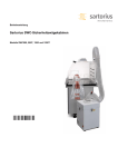
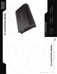
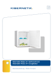
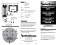
Fig. 1
SPECIFICATIONS
Rating:
1 farad
(RFC1 or RFC1D)
2 farad hybrid
(RFC2D)
VDC:
1 farad : 20V surge
2 farad : 18V surge
Tolerance:
±10%
1-Farad Capacitor
RFC1
Dimensions: 1 farad : 3" x 8.625" (76.2mm x 219mm)
2 farad : 3" x 8.625" (76.2mm x 219mm)
Digital Status Caps add 1.2" (30.5mm) to height
Connect to chassis
ground of vehicle*
Less
than
18"
*Keep Grounds as
short as possible
Fuse
ESR:
1 farad : <1.95m
2 farad : <3.00m
Terminals:
1/4" 28 thread
Tools:
3/16" Allen wrench
RFC1D
2-Farad Hybrid
Capacitor
Digital Display
WARRANTY INFORMATION
Capacitors are nearly indestructible and will provide years
of service if installed and used in accordance with the
instructions in this manual. If this product should prove to
be defective within a period of ninety (90) days from the
date of purchased, contact your dealer or Rockford
Corporation Customer Service Department at
1-800-669-9899 for replacement instructions.
Vehicle Battery
Fig. 2
3
In the event the vent is blown or leaking as a result of
switched polarity, the capacitor is not covered by warranty.
1
Stripped screws or terminals are not covered by warranty.
Replacements may be obtained at a resonable cost by
contacting Rockford Corporation Customer Service
Department at 1-800-669-9899
2
4
Rockford Corporation
546 South Rockford Drive
Tempe, AZ 85281 USA
USA, (480) 967-3565 - Customer Service 1-800-669-9899
Europe, Fax (49) 4207-8101250
Japan, Fax (81) 559-79-1265
12/06
Printed in China
1-Farad Capacitor
Digital Display
1230-53682-01
RFC2D
Installation &
Application Manual
INTRODUCTION
Thank you for purchasing the Rockford Fosgate
Capacitor or Hybrid Capacitor.
These capacitors allow you to help maintain continuous
power to other devices, such as amplifiers, in your
audio system.
Please read, understand and follow all instructions
before connecting the capacitor. If, after reading your
manual, you still have questions regarding this product,
we recommend that you see your Rockford Fosgate
dealer. If you need further assistance, you can call us
direct at 1-800-669-9899.
English
SAFETY INFORMATION
! CAUTION:
To prevent injury and damage to the unit, please read and
follow the instructions in this manual.
! CAUTION:
If you feel unsure about installing this system yourself, have it
installed by a qualified Rockford Fosgate technician.
! CAUTION:
Before installation, disconnect the battery negative (-) terminal
to prevent damage to the unit, fire and/or possible injury.
! CAUTION:
Polarity must be observed and maintained during
installation to eliminate the possibility of damaging the
capacitor, the battery, or other associated equipment.
DISCHARGING
INSTALLATION ET MONTAGE
1. Either mount the CHRG2 card on the capacitor or connect the Blue wire to the
Positive (+) post and the Yellow wire to the Negative (-) post on the capacitor.
Voir le schéma 1
2. Connect the Red and Black wires together.When the Red LED light goes out, the
capacitor is discharged.
NOTE: Due to the shape of the top of some capacitors, you will not be able to
mount the CHRG2 card directly to them.
DIGITAL STATUS CAP FEATURES
See Figure 2
Installation is simple and straightforward.When installing the capacitor, we recommend
using the same gauge wire as that of the power connection to the amplifier. Ground
the capacitor to the nearest chassis ground using the same gauge wire as that used
for the power connection. It is strongly recommended the capacitor be fused at the
battery.The fuse value should be the same as that of the power connection to the
amplifier.This fuse should be installed 18" or less from the battery (See illustration).
If the capacitor is to be used in a multi-amp system, a power distribution block may
be used between the capacitor and the amplifiers. It should be wired using the same
gauge wire as that of the main system.
The positive side of the capacitor will be connected to the positive side of the
amplifier’s power connection (B+).
! CAUTION:
Do Not Overtighten Screws! Stripped or broken terminals
are NOT covered by the warranty
Negative Terminal – Connect to chassis ground.
2.
Reverse Voltage Warning – A buzzer will sound if the capacitor is
connected backwards. Ensure that the Positive (+) and Negative (-) leads
are connected correctly.
3.
Positive Terminal – Connect to Positive (+) side of vehicle's battery.
4.
Voltage Indicator – With the system turned on, the display will show
the DC volts at the capacitor.
INFORMATIONS SUR LA SÉCURITÉ
Français
! MISE EN GARDE : pour éviter des blessures et ne pas endommager
l'appareil, veuillez lire et suivre les instructions de ce manuel.
INSTALLATION / MOUNTING
See Figure 1
! MISE EN GARDE : avant d'entamer l'installation, déconnectez la broche
The capacitor may be mounted in any position; however, care should be taken to
ensure the venting hole on the top is unobstructed at all times.This vent is a relief
valve should the electrical polarity become crossed. Should the capacitor be damaged,
fluid will exit from this vent rendering the capacitor useless.
! CAUTION: To prevent damage to the capacitor, do not install in locations
where it will be exposed to water, oil or mistreatment.
Install in a dry, safe place within 18" (0.5m) of the amplifier.The
positive lead connects to the terminal marked with a “+”
symbol.The negative terminal is not marked. If these wires are
reversed, fluid from inside the capacitor will leak out of the vent
plug on the top. Do not install a damaged cap. Use care when
handling damaged capacitors, treat them like a fully charged lead
acid battery.
CHARGING
1. Either mount the CHRG2 card on the capacitor or connect the Blue wire to the
Positive (+) post and the Yellow wire to the Negative (-) post on the capacitor.
2. Connect the Red wire to the Positive (+) side and the Black wire to the Negative
(-) side of a 12 volt DC power source.When the Green LED light goes out, the
capacitor is charged.
NOTE: Due to the shape of the top of some capacitors, you will not be able to
mount the CHRG2 card directly to them.
pas dans un lieu où il risque d'être exposé à de l'eau, de l'huile
ou un mauvais traitement.
Installez-le dans un endroit sec et sûr, à moins de 0,5 m (18 po)
de l'amplificateur. Connectez le fil positif à la borne portant le
symbole « + ». La borne négative, elle, ne porte aucune marque.
Si ces fil sont inversés, le fluide à l'intérieur du condensateur
fuira par le trou d'aération du haut. N'installez pas de
condensateur endommagé. Manipulez soigneusement les
condensateurs endommagés et traitez-les comme une batterie
hermétique pleinement chargée.
Auto Turn-On – Turns on the display during standard operation (voltage
fluctuation).After 5 minutes of non-use (no fluctuation) automatically
reverts to sleep mode.
! MISE EN GARDE : si vous vous sentez incapable d'installer l'appareil
vous-même, confiez la tâche à un technicien Rockford Fosgate
qualifié.
The Rockford Fosgate Reinforcement Capacitor should be mounted as close to the
amplifier as possible, within 18" (0.5m) of the amplifier, keeping the wire runs short to
reduce voltage losses in the cables. Use the mounting brackets supplied to secure the
capacitor as close to the amplifier as possible.
Le condensateur peut être monté dans n'importe quelle position; veillez toutefois à ce
que le trou d'aération du dessus ne soit jamais obstrué. Celui-ci sert de soupape de
décharge au cas où la polarité électrique deviendrait croisée. Si le condensateur est
endommagé, le fluide sort de ce trou et rend le condensateur inutilisable.
! MISE EN GARDE : pour éviter d'endommager le condensateur, ne l'installez
1.
POWER WIRING CONSIDERATIONS
Le condensateur de renfort Rockford Fosgate doit être monté aussi près de
l'amplificateur que possible, à moins de 0,5 m (18 po) de celui-ci, en maintenant les fils
courts afin de réduire les pertes de tension dans les câbles. Utilisez les supports de
montage fournis pour fixer le condensateur aussi près de l'ampli que possible.
négative (-) de la batterie pour éviter tout risque de blessures,
d'incendie ou de dommages à l'appareil.
! MISE EN GARDE : la polarité doit être respectée tout au long de l'installation
afin d'éviter d'endommager le condensateur, la batterie ou les
autres équipement connexes.
CÂBLAGE D'ALIMENTATION
L'installation est tout à fait simple. Nous recommandons d'utiliser durant l'installation
du condensateur un câblage de même calibre que celui de la connexion d'alimentation
de l'amplificateur. Mettez le condensateur à la masse au point le plus proche du châssis
en employant un câble du même calibre que celui utilisé pour la connexion
d'alimentation. Il est fortement recommandé de protéger le condensateur par un
fusible au niveau de la batterie. La valeur du fusible doit être identique à celle de la
connexion d'alimentation de l'amplificateur. Ce fusible doit être installé à 46 cm
(18 po) ou moins de la batterie (voir l'illustration).
Si le condensateur doit être employé dans un système comprenant plusieurs amplis, il
est possible d'utiliser un bloc de distribution d'alimentation entre le condensateur et
les amplis. Celui-ci doit être câblé à l'aide d'un câble de même calibre que celui du
système principal.
Le côté positif du condensateur doit être connecté au côté positif de la connexion
d'alimentation de l'ampli (B+).
! MISE EN GARDE : évitez de trop serrer les vis! Les bornes foirées ou
brisées ne sont PAS couvertes par la garantie.
CHARGE
1.
Installez la carte CHRG2 sur le condensateur ou connectez le fil bleu à la borne
positive (+) et le fil jaune à la borne négative (-) du condensateur.
2.
Connectez le fil rouge au côté positif (+) et le fil noir au côté négatif (-) d'une
source d'alimentation c.c. de 12 V. Le condensateur est chargé lorsque la diode
verte s'éteint.
REMARQUE : À cause de la forme de la partie supérieure de certains
condensateurs, vous ne pourrez pas fixer la carte CHRG2
directement sur eux.
DÉCHARGE
1.
Installez la carte CHRG2 sur le condensateur ou connectez le fil bleu à la
borne positive (+) et le fil jaune à la borne négative (-) du condensateur.
2.
Connectez les fils rouge et noir ensemble. Le condensateur est déchargé
lorsque la diode rouge s'éteint.
REMARQUE : À cause de la forme de la partie supérieure de certains
condensateurs, vous ne pourrez pas fixer la carte CHRG2
directement sur eux.
CARACTÉRISTIQUES DE L'AFFICHAGE NUMÉRIQUE
Voir le schéma 2
1.
Borne négative – Connectez-la à la masse du châssis.
2.
Avertissement de tension inverse – Une sonnerie retentira si le
condensateur est connecté à l'envers.Vérifiez que les fils positif (+) et négatif (-)
sont connectés correctement.
3.
Borne positive – Connectez au côté positif (+) de la batterie du véhicule.
4.
Indicateur de tension – Lorsque le système est allumé, l'affichage indique la
tension de courant continu du condensateur.
La fonction Auto Turn-On (allumage automatique) – allume l'affichage en
mode de fonctionnement normal (fluctuation de tension).Après 5 minutes de
non-utilisation (sans fluctuation), le mode de veille s'active
automatiquement.
Español
INFORMACIÓN SOBRE SEGURIDAD
! PRECAUCIÓN: Para evitar lesiones y daños a la unidad, por favor lea y cumpla
CARGA
1.
Monte la tarjeta CHRG2 en el capacitor o conecte el cable azul al borne
positivo (+) y el cable amarillo al borne negativo (-) en el capacitor.
2.
Conecte el cable rojo al lado positivo (+) y el cable negro al lado negativo (-)
de una fuente de alimentación de 12 voltios de CC. Cuando se apague la luz del
LED verde, el capacitor está cargado.
las instrucciones de este manual.
! PRECAUCIÓN: Si no tiene la certeza de poder instalar el sistema, hágalo
instalar por una persona técnicamente calificada de Rockford
Fosgate.
! PRECAUCIÓN:Antes de la instalación, desconecte el terminal negativo (-)
de la batería para que evite posibles lesiones, daños a la unidad
o incendio.
! PRECAUCIÓN: La polaridad se debe observar y conservar durante la insta-
lación, para eliminar la posibilidad de daños en el condensador, la
batería u otros equipos asociados.
CONSIDERACIONES PARA EL CABLEADO DE CORRIENTE
NOTA: Debido a la forma de la parte superior de algunos capacitores, usted no
podrá montar la tarjeta CHRG2 directamente en los mismos.
EINBAU / BEFESTIGUNG
Sehen Sie Abbildung 1
2.
Conecte juntos los cables rojo y negro. Cuando se apaga la luz del LED rojo,
el capacitor está descargado.
NOTA: Debido a la forma de la parte superior de algunos capacitores, usted no
podrá montar la tarjeta CHRG2 directamente en los mismos.
Véase el Fig. 2
1.
Terminal negativo – Conectarlo a tierra en la carrocería.
2.
Advertencia de polaridad invertida – Se escuchará un zumbador si el
capacitor está conectado al revés.Asegúrese de que los conductores positivo (+)
y negativo (-) estén conectados correctamente.
3.
Terminal Positivo – Conectarlo al lado Positivo (+) de la batería del
vehículo.
4.
Indicador de Tensión – Con el sistema prendido, la pantalla mostrará los
voltios de CC en el condensador.
SICHERHEITSHINWEISE
El Condensador de Refuerzo Rockford Fosgate se debe montar tan cerca del
amplificador como sea posible, a 18" (0.5m) del amplificador, manteniendo el tiraje
del cable bien corto, para reducir la pérdida de tensión en los cables. Utilice los
soportes de montura suministrados para asegurar el condensador tan cerca del
amplificador como le sea posible.
El condensador se puede montar en cualquier posición, no obstante, debe tener
cuidado en asegurarse de que el respiradero de la parte superior no esté obstruido
en ningún momento. Ese respiradero es una válvula de escape en caso de que la
polaridad eléctrica se cruce. Si se daña el condensador, saldrá un líquido de ese
respiradero y el condensador quedará inservible.
! PRECAUCIÓN: Para evitarle daños al condensador, no lo instale en puntos
en donde quede expuesto al agua, aceite o maltratos.
Instálelo en un lugar seguro, seco, a 18" (0.5m) del amplificador.
El cable positivo se conecta al terminal que está marcado con
símbolo “+”. El terminal negativo no está marcado. Si se
invierten estos cables, saldrá líquido del respiradero del
condensador en la parte superior. No instale un condensador
dañado.Tenga cuidado cuando manipule condensadores
dañados, trátelos como una batería de plomo completamente
cargada.
Der Rockford Fosgate-Verstärkungskondensator sollte so nah wie möglich vom
Verstärker befestigt, und zwar höchstens 0,5 m vom Verstärker. Die kurze Kabellänge
reduziert Spannungsverlust in den Kabeln. Die mitgelieferten Befestigungsteile
verwenden, um den Kondensator so nah wie möglich vom Verstärker zu befestigen.
Der Kondensator kann in jeder beliebigen Position befestigt werden; jedoch muss
das Lüftungsloch auf der Oberseite stets frei sein. Diese Lüftungsöffnung dient als
Sicherheitsventil, sollte die elektrische Polarität gekreuzt werden. Sollte der
Kondensator beschädigt werden, tritt Flüssigkeit aus dieser Öffnung und der
Kondensator verliert seine Funktionstüchtigkeit.
! VORSICHT: Um Schäden am Kondensator zu verhindern, den Kondensator
nicht an Stellen befestigen, wo er Wasser, Öl oder Misshandlung
ausgesetzt ist.
An einer trockenen, sicheren Stelle höchstens 0,5 m vom
Verstärker entfernt einbauen. Der positive Pol wird am mit
einem „+“ markierten Anschluss angeschlossen. Der negative
Pol ist nicht markiert.Wenn diese Kabel vertauscht werden,
läuft Flüssigkeit aus dem Inneren des Kondensators durch den
Verschlussstopfen auf der Oberseite. Keinen beschädigten
Kondensator anbringen.Vorsicht ist bei der Handhabung von
beschädigten Kondensatoren geboten. Sie müssen wie eine
vollständig geladene Bleibatterie behandelt werden.
Auto Turn-On (encendido automático) – Enciende la pantalla durante el
funcionamiento estándar (fluctuación del voltaje). Después de 5 minutos de no
ser usado (no hay fluctuación) cambia automáticamente al modo en espera.
INSTALACIÓN / MONTAJE
Véase el Fig. 1
Anschlüsse sind NICHT von der Garantie gedeckt.
Monte la tarjeta CHRG2 en el capacitor o conecte el cable azul al borne
positivo (+) y el cable amarillo al borne negativo (-) en el capacitor.
Si el condensador se va a utilizar en un sistema con varios amplificadores, se puede
utilizar una barra para distribución de corriente entre el condensador y los amplificadores. El cableado debe ser del mismo calibre que el del sistema principal,
o con roscas dañadas NO están cubiertos por la garantía.
! VORSICHT: Die Schrauben nicht überziehen! Überdrehte oder gebrochene
1.
CARACTERÍSTICAS DIGITALES DEL ESTATUS DEL CONDENSADOR
! PRECAUCIÓN: ¡No apriete los tornillos demasiado! Los terminales partidos
Die positive Seite des Kondensators wird an die positive Seite am Stromanschluss
des Verstärkers (B+).
DESCARGA
La instalación es simple y clara. Cuando se instale el condensador, recomendamos que
se use el mismo calibre de cable que el de la conexión de corriente al amplificador.
Conecte el condensador a tierra en el punto más cercano de la carrocería, utilizando
el mismo calibre de cable que utilizó para la conexión de la corriente. Se recomienda
firmemente que se le ponga un fusible al condensador en la batería. La equivalencia
del fusible debe ser igual a la de la conexión de corriente al amplificador. El fusible se
debe instalar a 18" (45.72 cm.) o menos de la batería (Ver ilustración).
El lado positivo del condensador se conectará al lado positivo de la conexión de
corriente del amplificador (B+).
Wenn der Kondensator in einem System mit mehreren Verstärkern eingesetzt werden
soll, kann ein Stromverteilerblock zwischen dem Kondensator und den Verstärkern
verwendet werden. Der Block sollte unter Verwendung der gleichen Kabelstärke
angeschlossen werden wie das Hauptsystem.
Deutsch
! VORSICHT: Zur Vermeidung von Verletzungen oder Schäden am Gerät
lesen und befolgen Sie bitte die Anweisungen in dieser
Anleitung.
AUFLADUNG
1.
Die CHRG2-Karte entweder auf dem Kondensator befestigen oder das blaue
Kabel an der positiven (+) Stütze und das gelbe Kabel an der negativen (-) Stütze
auf dem Kondensator anschließen.
2.
Das rote Kabel am positiven (+) Pol und das schwarze Kabel am negativen
(-) Pol einer 12 V Gleichstromquelle anschließen.Wenn die grüne LED erlischt,
ist der Kondensator geladen.
! VORSICHT: Wenn Sie unsicher sind, ob Sie dieses System selbst einbauen
können, lassen Sie es bei einem Rockford FosgateVertragshändler einbauen.
! VORSICHT: Trennen Sie vor dem Einbau den Negativpol von der Battery,
um Geräteschäden, Feuer bzw. mögliche Verletzungen zu
verhindern.
! VORSICHT: Die Polarität muss während des Einbaus beachtet und aufrecht
erhalten werden, um Schäden am Kondensator, der Batterie
oder anderen angeschlossenen Geräten auszuschließen.
ERWÄGUNGEN HINSICHTLICH DES STROMKABELS
Der Einbau ist einfach und unkompliziert.Wir empfehlen, beim Einbau des
Kondensators die gleiche Kabelstärke zu verwenden wie für die Stromverbindung zum
Verstärker. Den Kondensator mit der gleichen Kabelstärke, die auch für die
Stromverbindung verwendet wird, an der nächsten Erdungsmöglichkeit am Fahrgestell
erden. Es wird sehr empfohlen, den Kondensator an der Batterie mit einer Sicherung
versehen wird. Die Sicherung sollte den gleichen Wert haben wie die Stromverbindung
zum Verstärker. Diese Sicherung sollte maximal 0,5 m von der Batterie entfernt
eingebaut werden (siehe Zeichnung).
HINWEIS: Bei manchen Kondensatoren ist es auf Grund der Form der Oberseite
nicht möglich, die CHRG2-Karte direkt dort zu befestigen.
ENTLADUNG
1.
Die CHRG2-Karte entweder auf dem Kondensator befestigen oder das blaue
Kabel an der positiven (+) Stütze und das gelbe Kabel an der negativen (-) Stütze
auf dem Kondensator anschließen.
2.
Das rote und das schwarze Kabel zusammen anschließen.Wenn die rote LED
erlischt, ist der Kondensator geladen.
HINWEIS: Bei manchen Kondensatoren ist es auf Grund der Form der Oberseite
nicht möglich, die CHRG2-Karte direkt dort zu befestigen.
CHARAKTERISTIKEN DES DIGITALSTATUSKONDENSATORS
Sehen Sie Abbildung 2
1.
Negativer Anschluss – An der Fahrgestellerdung anschließen.
2.
Achtung Umpolspannung – Ein Summer ertönt, wenn der Kondensator
rückwärts angeschlossen ist. Die positiven (+) und negativen (-) Kabeladern
müssen ordnungsgemäß angeschlossen werden.
3.
Positiver Anschluss – An den positiven (+) Anschluss der Fahrzeugbatterie
anschließen.
4.
Spannungsanzeige – Bei eingeschaltetem System zeigt die Anzeige die
Gleichstromspannung am Kondensator an.
Il condensatore potrà essere montato in qualsiasi posizione; ciononostante, dovrete
aver cura per assicurarvi che il foro di ventilazione ubicato alla sommità non venga mai
ostruito. Questo foro fungerà da valvola di sfogo qualora la polarità elettrica dovesse
incrociarsi. Se il condensatore dovesse subire danni, il fluido che uscirà da questo foro
lo renderà inutile.
! ATTENZIONE: Per prevenire danni al condensatore, non installatelo in
luoghi dove sarà esposto ad acqua o ad olio oppure potrebbe
subire maltrattamenti.
Installatelo in un luogo asciutto e sicuro entro 0,5 m
dall’amplificatore. Il cavo positivo deve essere collegato al
terminale recante il simbolo “+” mentre il terminale negativo
non è segnato. Se questi fili venissero invertiti, il fluido
all’interno del condensatore uscirebbe dal foro di sfogo ubicato
alla sommità. Non installate un condensatore danneggiato.
Abbiate cura nel maneggiare i condensatori danneggiati e
trattateli come un accumulatore al piombo a piena carica.
Auto Turn-On (Automatisches Einschalten) – Schaltet die Anzeige
während des gewöhnlichen Betriebs ein (Spannungsfluktuation). Nach
fünfminütiger Nichtbenutzung (keine Fluktuation) kehrt die Anzeige automatisch
in den Ruhezustand zurück.
Italiano
INFORMAZIONI DI SICUREZZA
! ATTENZIONE: Per prevenire le lesioni personali e i danni all’unità, vi
preghiamo di leggere e di seguire le istruzioni contenute in
questo manuale.
! ATTENZIONE: Se aveste dei dubbi circa l’installazione rivolgetevi ad un
CARICAMENTO
1.
Fissare la scheda CHRG2 sul condensatore o collegare il cavo blu al terminale
positivo (+) e il cavo giallo al terminale negativo (-) del condensatore stesso.
2.
Collegare il cavo rosso al lato positivo (+) e il cavo nero al lato negativo (-)
di un alimentatore a 12 volt CC. Quando la spia LED verde si spegne, il
condensatore è carico.
tecnico qualificato della Rockford Fosgate.
! ATTENZIONE: Prima dell’installazione, scollegate il terminale negativo (-)
della batteria per evitare danni all’unità, pericoli d’incendio e/o
potenziali lesioni personali.
! ATTENZIONE: Osservate e mantenete la corretta polarità durante
l’installazione per eliminare qualsiasi possibilità di arrecare danni
al condensatore, alla batteria o ad altre attrezzature connesse.
CONSIDERAZIONI INERENTI AL CABLAGGIO DI POTENZA
L’installazione è semplice e di facile esecuzione. Quando installate il condensatore, è
raccomandabile usare del filo avente lo stesso diametro di quello usato per collegare
a potenza l’amplificatore. Collegate il condensatore alla messa a terra del telaio più
vicina, usando filo avente lo stesso diametro di quello usato per il collegamento a
potenza.Vi raccomandiamo vivamente di munire il condensatore di fusibile a livello
della batteria. Il valore del fusibile dovrebbe essere uguale a quello usato per collegare
a potenza l’amplificatore. Questo fusibile dovrebbe essere installato a circa 0,5 m o
meno dalla batteria (vedete l’illustrazione).
Se il condensatore è destinato all’uso in un sistema a multi-amp, si potrà usare un
quadro di distribuzione a potenza tra il condensatore e gli amplificatori. Dovrebbe
essere cablato con filo avente lo stesso diametro di quello del sistema principale.
NOTA: a causa della forma della parte superiore di alcuni condensatori,
potrebbe non essere possibile fissare la scheda CHRG2 direttamente
sul condensatore.
SCARICAMENTO
1.
Fissare la scheda CHRG2 sul condensatore o collegare il cavo blu al terminale
positivo (+) e il cavo giallo al terminale negativo (-) del condensatore stesso.
2.
Collegare tra di loro il cavo rosso e quello nero. Quando la spia LED rossa si
spegne, il condensatore è scarico.
NOTA: a causa della forma della parte superiore di alcuni condensatori,
potrebbe non essere possibile fissare la scheda CHRG2 direttamente
sul condensatore.
CARATTERISTICHE DELL’INDICATORE DI STATO DEL CONDENSATORE – TIPO
DIGITALE
Si veda la figura 2
1.
Terminale negativo – Collegatelo alla messa a terra del telaio.
2.
Segnalazione di tensione inversa – Se i collegamenti sul condensatore sono
scambiati, viene emesso un segnale acustico.Verificare che i cavi positivo (+) e
negativo (-) siano collegati correttamente.
3.
Terminale positivo – Collegatelo al lato positivo (+) della batteria del
veicolo.
4.
Indicatore di voltaggio – Con il sistema acceso, il display visualizzerà i volt in
CC al condensatore.
Il lato positivo del condensatore verrà collegato al lato positivo del collegamento a
potenza dell’amplificatore (B+).
! ATTENZIONE: Non stringete troppo le viti! I terminali spelati o rotti
NON sono coperti dalla garanzia.
INSTALLAZIONE / MONTAGGIO
Si veda la figura 1
Il condensatore di rinforzo della Rockford Fosgate dovrebbe essere montato il più
vicino possibile all’amplificatore, entro 0,5 m da quest’ultimo, con i percorsi dei fili
piuttosto corti per ridurre perdite di tensione nei cavi. Usate le staffe di montaggio
fornite per fissare il condensatore il più vicino possibile all’amplificatore.
Auto Turn-On (Accensione automatica ) – Accende il display durante il
normale funzionamento (fluttuazioni di tensione). Dopo cinque minuti di non
utilizzo (assenza di fluttuazioni), ritorna automaticamente alla modalità di
consumo energetico ridotto.