1
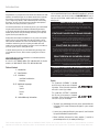
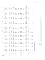
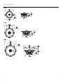
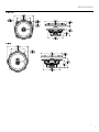
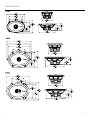
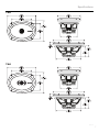
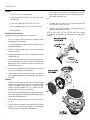
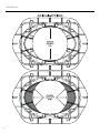
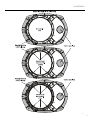
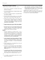
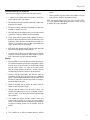
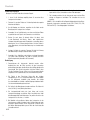
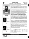
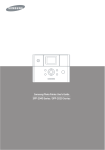
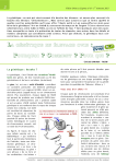
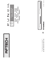
071111 BCF
1230-57046-01
Printed in China
R O C K F O R D F O S G AT E . C O M
600 South Rockford Drive • Tempe, Arizona 85281 United States
Direct: (480) 967-3565 • Toll Free: (800) 669-9899
www.rockfordfosgate.com/rftech
Installation assistance availible at:
Serial Number:
Date of Purchase:
Installation & Operation
P1683
P1675
P152
P1694
P1462
P165
P142
P1692
P1572
P16
P132
FULL RANGE
SPEAKERS
Introduction
Dear Customer,
Congratulations on your purchase of the world’s finest brand of car audio
amplifiers. At Rockford Fosgate we are fanatics about musical reproduction at its best, and we are pleased you chose our product. Through
years of engineering expertise, hand craftsmanship and critical testing
procedures, we have created a wide range of products that reproduce
music with all the clarity and richness you deserve.
For maximum performance we recommend you have your new Rockford
Fosgate product installed by an Authorized Rockford Fosgate Dealer,
as we provide specialized training through Rockford Technical Training
Institute (RTTI). Please read your warranty and retain your receipt and
original carton for possible future use.
Great product and competent installations are only a piece of the puzzle
when it comes to your system. Make sure that your installer is using
100% authentic installation accessories from Rockford Fosgate in your
installation. Rockford Fosgate has everything from RCA cables and
speaker wire to power wire and battery connectors. Insist on it! After all,
your new system deserves nothing but the best.
To add the finishing touch to your new Rockford Fosgate image order
your Rockford accessories, which include everything from T-shirts to
jackets.
Visit our web site for the latest information on all Rockford products;
If, after reading your manual, you still have questions regarding this product, we recommend that you see your Rockford Fosgate dealer. If you need
further assistance, you can call us direct at 1-800-669-9899. Be sure to
have your serial number, model number and date of purchase available
when you call.
PRACTICE SAFE SOUND
Continuous exposure to sound pressure levels over 100dB may cause
permanent hearing loss. High powered auto sound systems may
produce sound pressure levels well over 130dB. Use common sense
and practice safe sound.
PRATIQUEZ UNE ÉCOUTE SANS RISQUES
Une exposition continue à des niveaux de pression acoustique upérieurs à
100 dB peut causer une perte d’acuité auditive permanente. Les systèmes
audio de forte puissance pour auto peuvent produire des niveaux de
pression acoustique bien au-delà de 130 dB. Faites preuve de bon sens et
pratiquez une écoute sans risques
PRACTIQUE EL SONIDO SEGURO
El contacto continuo con niveles de presión de sonido superiores a 100
dB puede causar la pérdida permanente de la audición. Los sistemas de
sonido de alta potencia para automóviles pueden producir niveles de
presión de sonido superiores a los 130 dB. Aplique el sentido común y
practique el sonido seguro.
PRAKTIZIEREN SIE SICHEREN SOUND
www.rockfordfosgate.com
or, in the U.S. call 1-800-669-9899 or FAX 1-800-398-3985. For all other
countries, call +001-480-967-3565 or FAX +001-480-966-3983.
Fortgesetzte Geräuschdruckpegel von über 100 dB können beim
Menschen zu permanentem Hörverlust führen. Leistungsstarke
Autosoundsysteme können Geräuschdruckpegel erzeugen, die weit über
130 dB liegen. Bitte wenden Sie gesunden Menschenverstand an und
praktizieren Sie sicheren Sound.
Table of Content
OSSERVATE LE REGOLE DEL SUONO SENZA PERICOLI
2 Introduction
3-7 Specifications
8-11 Installation
Installation Considerations
Mounting
12-15 Additional Languages
French
Spanish
German
Italian
16 Limited Warranty Information
La costante esposizione a livelli di pressione acustica al di sopra dei
100dB possono causare la perdita permanente dell’udito. I sistemi
audio ad alta potenza possono produrre livelli di pressione acustica ben
superiori ai 130dB. Si consiglia il buon senso e l’osservanza delle regole
del suono senza pericoli
Safety
This symbol with “WARNING” is intended
to alert the user to the presence of important
instructions. Failure to heed the instructions
will result in severe injury or death.
This symbol with “CAUTION” is intended to
alert the user to the presence of important
instructions. Failure to heed the instructions
can result in injury or unit damage.
•To prevent injury and damage to the unit, please read and follow the
instructions in this manual. We want you to enjoy this system, not get
a headache.
•If you feel unsure about installing this system yourself, have it installed
by a qualified Rockford Fosgate technician.
•Before installation, disconnect the battery negative (-) terminal to
prevent damage to the unit, fire and/or possible injury.
©2011 Rockford Corporation. All Rights Reversed. ROCKFORD FOSGATE, PUNCH, and associated logos where applicable are registered trademarks of Rockford
Corporation in the United States and/or other countries. All other trademarks are the property of their respective owners. Specifications subject to change without notice.
2
3.5”
(89mm)
P132
20W / 40W
86.5dB
89.5dB
Sensitivity (1W/1M) 85dB
Sensitivity (2.83V/1M) 88dB
5”x7” /
6”x9”
4”x6” /
6”x8”
P16
5”x7” /
6”x9”
YES
1.93”
(49.0mm)
5.05”
(128.2mm)
0.14”
(3.5mm)
91dB
88dB
0.60ft3
(16.8L)
0.68
65 Hz
55W / 110W
1.0”
(25.4mm)
65-22kHz
4Ω
2-Way
6”
(153mm)
5”x7” /
6”x9”
YES
1.93”
(49.0mm)
5.05”
(128.2mm)
0.14”
(3.5mm)
91dB
88dB
0.60ft3
(16.8L)
0.68
65 Hz
55W / 110W
1.0”
(25.4mm)
65-22kHz
4Ω
2-Way
6.5”
(165mm)
P165
5”x7” /
6”x9”
YES
2.24”
(57.0mm)
5.68”
(144.2mm)
0.14”
(3.5mm)
92dB
89dB
0.60ft3
(16.8L)
0.68
60 Hz
60W / 120W
1.0”
(25.4mm)
60-24kHz
4Ω
3-Way
6.75”
(171.5mm)
P1675
6”x8”
NO
1.89”
(48.0mm)
3.76”x6.01”
(95.6x152.6mm)
0.08”
(2.0mm)
90.5dB
87.5dB
0.08ft3
(2.2L)
0.80
90 Hz
35W / 70W
1.0”
(25.4mm)
90-22kHz
4Ω
2-Way
4” x 6”
(102x152mm)
P1462
6”x8”
NO
2.30”
(58.5mm)
4.76”x7.02”
(120.9x178.4mm)
0.08”
(2.0mm)
92dB
89dB
0.19ft3
(5.4L)
0.68
75 Hz
60W / 120W
1.0”
(25.4mm)
75-22kHz
4Ω
2-Way
5” x 7”
(127 x 178mm)
P1572
NO
NO
2.32”
(59.0mm)
5.08”x7.26”
(129.0x184.3mm)
0.14”
(3.5mm)
93dB
90dB
0.48ft3
(13.6L)
1.00
65 Hz
65W / 130W
1.0”
(25.4mm)
65-24kHz
4Ω
3-Way
6” x 8”
(152 x 203mm)
P1683
Power ratings on Rockford Fosgate amplifiers conform to CEA-2006 industry standards. These guidelines mean
your amplifier’s output power ratings are REAL POWER numbers, not inflated marketing ratings.
CEA 2006
See pages 4-7 for additional dimensions.
Adaptor Plate NO
1.91”
(48.5mm)
YES
1.75”
(44.5mm)
1.46”
(37.0mm)
Mounting Depth
4.81”
(122.2mm)
0.08”
(2.0mm)
90dB
87dB
0.19ft3
(5.4L)
0.68
70 Hz
40W / 80W
1.0”
(25.4mm)
70-22kHz
4Ω
2-Way
5.25”
(133)
P152
NO
4.04”
(102.5mm)
3.21”
(81.6mm)
Mounting Diameter
Grille/Trim Ring NO
0.06”
(1.5mm)
0.04”
(1.0mm)
Xmax
Vas
0.09ft3
(2.5L)
0.80
100 Hz
30W / 60W
1.0”
(25.4mm)
0.03ft3
(0.9L)
Qts 0.60
Fs - Free Air Resonance 120 Hz
(RMS/Peak)
Power Rating
0.75”
(20mm)
100-22kHz
Frequency Response 120-22kHz
Voice Coil Diameter
4Ω
2-Way
4.0”
(102mm)
P142
Nominal Impedance 4Ω
Description 2-Way
Nominal Diameter
Model
NO
YES
3.07”
(78.0mm)
5.77”x8.51”
(146.5x216.2mm)
0.18”
(4.5mm)
94dB
91dB
0.78ft3
(22.0L)
0.72
60 Hz
75W / 150W
1.0”
(25.4mm)
60-22kHz
4Ω
2-Way
6”
(153mm)
P1692
NO
YES
3.07”
(78.0mm)
5.77”x8.51”
(146.5x216.2mm)
0.18”
(4.5mm)
94dB
91dB
0.78ft3
(22.0L)
0.72
60 Hz
75W / 150W
1.0”
(25.4mm)
60-24kHz
4Ω
4-Way
6”
(153mm)
P1694
Specifications
3
Specifications
illus.-1.1
4
Specifications
illus.-1.2
5
Specifications
illus.-1.3
6
Specifications
illus.-1.4
7
Installation
Contents
•(1) Pair Punch Series Full Range Speakers
5. On models with slotted holes, fit the speaker into the cutout and
install the screws in the slots at the top and bottom.This will allow
you to rotate the speaker to match the remaining mounting holes.
When aligned, tighten the screws.
•(1) Pair of grilles/trim rings (P152, P16, P165, P1675, P1692
and P1694 only)
OR
•(1) Pair of 5x7 adapter plates (P142, P1462, P1572 only)
6. On models with a trim ring, fit the trim ring over the speaker and
mount into place using four (4) screws.
•(1) Pair of 6x9 adapter plates (P152, P16, P165, P1675 only)
•Mounting Hardware
Installation Considerations
Before beginning any installation, follow these simple rules:
7. Tighten the screws until the speaker is snug in place to prevent
rattling. Do not over tighten the screws.
NOTE: For P142, P1462, P152, P16, P165 and P1675 only, if needed
use the adapter plate provided to mount the speaker. See Adapter Plate
Templates.
1. Be sure to carefully read and understand the instructions before
attempting to install these speakers.
illus.-2.1
2. For safety, disconnect the negative lead from the battery prior to
beginning the installation.
3. For easier assembly, we suggest you run all wires prior to mounting
your speakers in place.
4. Use high quality connectors for a reliable installation and to minimize
signal or power loss.
5. Think before you drill! Be careful not to cut or drill into gas tanks, fuel
lines, brake or hydraulic lines, vacuum lines or electrical wiring when
working on any vehicle. If installation in a boat, take care not to cut or
drill through the main hull.
6. Never run wires underneath the vehicle. Running the wires inside the
vehicle or hull area provides the best protection.
7. Avoid running wires over or through sharp edges. Use rubber or
plastic grommets to protect any wires routed through metal, especially
the firewall.
illus.-2.2
Mounting
1. Determine where the speakers will be mounted. Ensure an area large
enough for the speaker to mount evenly. Be sure that the mounting
location is deep enough for the speaker to fit; if mounting in a door,
operate all functions (windows, locks, etc.) through their entire
operating range to ensure there is no obstruction.
2. Refer to the specification chart to determine the proper diameter hole
to cut for your speaker model. Cutting and mounting templates can be
found at www.rockfordfosgate.com.
3. Mark the locations for the mounting screws. Drill the holes with a
1/8” bit.
4. Feed the speaker wires through the cutout and connect to the speaker
terminals. Be sure to observe proper polarity when connecting the
wires.The speaker’s positive terminal is indicated with a “+”.
8
illus.-2.3
Installation
illus.-3.1
9
Installation
illus.-3.2
10
Installation
illus.-3.3
11
Français
Considérations Concernant L’installation
Avant de commencer l’installation, suivez les règles ci-dessous:
1. Veillez à bien lire et comprendre les instructions avant d’essayer
d’installer les haut-parleurs.
2. Par mesure de sécurité, débranchez le fil négatif de la batterie avant de
commencer l’installation.
3. Pour faciliter le montage des haut-parleurs, il est conseillé d’installer
tous les câbles au préalable.
4. Utilisez des connecteurs de haute qualité pour assurer une installation
fiable et réduire au minimum la perte de signal ou de puissance.
5. Réfléchissez bien avant de percer.Veillez à ne pas couper ou percer
le réservoir d’essence, le câblage électrique ou les conduites de
carburant, de freinage hydraulique ou de dépression en travaillant
sur un véhicule. En cas d’installation sur un bateau, veillez à ne pas
couper ou percer la coque principale.
6. Ne jamais faire passer de fils sous le véhicule. Leur installation à
l’intérieur du véhicule ou de la coque assure la meilleure protection.
7. Évitez de faire passer des fils sur des bords tranchants ou dans
des orifices à arêtes vives. Utilisez des bagues en caoutchouc ou
en plastique pour protéger les fils traversant une plaque de métal,
notamment le tablier.Emplacements De Montage
Montage
1. Déterminez l’emplacement des haut-parleurs.Veillez à ce que la
surface plane soit assez grande pour assurer un contact uniforme
du haut-parleur.Vérifiez que l’emplacement est assez profond pour le
haut-parleur ; en cas de montage dans une portière, actionnez toutes
les commandes (fenêtres, serrures, etc.) jusqu’aux extrémités de leurs
courses pour vous assurer qu’il n’y a pas d’obstruction.
2. Consultez le tableau des caractéristiques pour déterminer le diamètre
de l’orifice à découper pour votre modèle de haut-parleur. Le gabarit
fourni donne aussi le bon diamètre de découpe.Les gabarits de coupe
et de montage sont disponibles sur la page www.rockfordfosgate.
com/rftech.
3. Marquez l’emplacement des vis de montage. Percez les trous avec
une mèche de 1/8 de pouce (3,2 mm).
4. Faites passer les fils de haut-parleur à travers l’orifice découpé et
branchez-les aux bornes du haut-parleur.Veillez à bien respecter la
polarité lors du branchement. La borne positive du haut-parleur est
indiquée par un « + ».
5. Sur les modèles à trous allongés, mettez le haut-parleur en place dans
la découpe et installez les vis dans les trous du haut et du bas.Vous
pourrez alors faire tourner le haut-parleur pour l’aligner sur les autres
trous de montage. Une fois cet alignement effectué, serrez les vis.
OU
6. Sur les modèles à anneau de garniture, placez celui-ci sur le hautparleur et fixezle avec quatre vis.
12
7. Serrez les vis jusqu’à ce que le haut-parleur soit bien ajusté, de façon à
prévenir tout cliquetis, mais évitez tout serrage excessif.REMARQUE:
Nous recommandons l’utilisation d’un fil de 4AWG pour les prises
d’alimentation (B+) et de masse (GND). Préparez le fil d’alimentation ROUGE
à connecter à l’amplificateur en dénudant son extrémité sur 13 mm. Insérez la partie
dénudée dans la borne B+, puis fixez le fil en vissant la vis sans tête.
REMARQUE: Pour les modèles P142, P1462, P152, P16, P165 et P1675
seulement, utilisez si nécessaire la plaque d’adaptation fournie pour monter le haut-parleur.Voir les gabarits de plaque d’adaptation.
Español
Consideraciones para la instalación
Antes de comenzar cualquier instalación, siga estas simples normas:
1. 1. Asegúrese de leer cuidadosamente y de entender las instrucciones
antes de tratar de instalar estos altavoces.
2. Por seguridad, desconecte el conductor negativo de la batería antes
de comenzar la instalación.
acabado arriba del altavoz y móntelo en su sitio usando cuatro (4)
tornillos.
7. Apriete los tornillos hasta que el altavoz esté ajustado en su sitio para
evitar vibraciones. No apriete demasiado los tornillos.
NOTA: Si es necesario, sólo para P142, P1462, P152, P16, P165 y P1675,
use la placa adaptadora proporcionada para montar el altavoz. Consulte
las plantillas de las placas adaptadoras.
3. Para facilitar el montaje, sugerimos que tienda todos los cables antes
de montar sus altavoces en su sitio.
4. Utilice conectores de alta calidad para tener una instalación confiable
y para reducir al mínimo las pérdidas de señal o de potencia.
5. ¡Piense siempre antes de perforar! Tenga cuidado de no cortar ni
perforar en tanques de combustible, tuberías de combustible, frenos
o hidráulicas, tuberías de vacío o cableado eléctrico al trabajar en un
vehículo. Si la instalación se hace en un bote, tenga cuidado de no
cortar ni perforar a través del casco principal.
6. Nunca tienda cables abajo del vehículo.Tender los cables adentro del
vehículo o casco proporciona la mejor protección.
7. Evite tender cables arriba o a través de bordes filosos. Use arandelas
aislantes de caucho para proteger los cables tendidos a través de
metal, especialmente la mampara cortafuegos.Montage
Montaje
1. Determine adónde se montará los altavoces.Asegúrese de que haya un
área suficientemente grande para montar de manera plana el altavoz.
Asegúrese de que el lugar de montaje sea suficientemente profundo
para que quepa el altavoz, si se monta en una puerta, accione
todas las funciones (ventanas, cerradura, etc.) en toda su gama de
funcionamiento para asegurarse de que no haya obstrucciones.
2. Consulte la tabla de especificaciones para determinar cuales son
los diámetros correctos para el agujero a cortar para su modelo de
altavoz. La plantilla proporcionada también le da la medida correcta
del recorte.Se puede hallar las plantillas para el corte y el montaje en
www.rockfordfosgate.com/rftech.
3. Marque las localidades para los tornillos de montaje. Perfore los
agujeros usando una broca de 1/8 pulg.
4. Tienda los cables del altavoz a través del recorte y conecte a los
terminales del altavoz.Asegúrese de usar la polaridad correcta al
conectar los cables. El terminal positivo del altavoz está identificado
con un símbolo “+”.
5. En los modelos con agujeros ranurados, coloque el altavoz en el
recorte e instale los tornillos en las ranuras en la parte superior e
inferior. Esto le permitirá hacer girar el altavoz para que coincida con
los agujeros de montaje restantes. Una vez alineados, apriete los
tornillos.
O
6. En los modelos con un anillo de acabado, coloque el anillo de
13
Deutsch
Einbauüberlegungen
Befolgen Sie vor dem Einbau diese einfachen Regeln:
6. An Modellen mit einem Zierring den Zierring über den Lautsprecher
legen und mit 4 (vier) Schrauben an seinem Platz befestigen.
1. 1. Lesen Sie die Anleitung sorgfältig, bevor Sie versuchen diese
Lautsprecher einzubauen.
7. Die Schrauben anziehen, bis der Lautsprecher eng an seinem Platz
anliegt, um Klappern zu verhindern. Die Schrauben nicht zu fest
anziehen.
2. Entfernen Sie vor dem Einbau aus Sicherheitsgründen das negative
Kabel von der Batterie.
3. Um die Montage zu erleichtern, empfehlen wir alle Kabel vor der
Befestigung Ihrer Lautsprecher zu verlegen.
4. Verwenden Sie nur Qualitätsstecker, um einen zuverlässigen Einbau
zu gewährleisten und Signal- und Stromverlust zu minimieren.
5. Denken Sie nach, bevor Sie bohren! Achten Sie darauf, nicht
in den Benzintank, die Benzin-, Brems- oder hydraulischen
Leitungen,Vakuumleitungen oder Elektrokabel zu schneiden oder zu
bohren,wenn Sie am Fahrzeug arbeiten.Achten Sie beim Einbau in
einem Boot darauf, nicht durch den Bootsrumpf zu schneiden oder
zu bohren.
6. Verlegen Sie Kabel nie unter dem Fahrzeug. Die Kabel im Fahrzeug
oder Bootsrumpf zu verlegen, bietet den besten Schutz.
7. Vermeiden Sie es, Kabel über scharfe Kanten zu verlegen.Verwenden
Sie Gummi- oder Plastikringe, um Kabel zu schützen, die durch
Metall verlegt werden (besonders die Feuerwand).
Befestigung
1. Entscheiden,wo die Lautsprecher befestigt werden sollen.
Gewährleisten, dass der Platz ausreicht, um den Lautsprecher
gleichmäßig zu befestigen. Gewährleisten, dass die Befestigungsstelle
ausreichende Tiefe für den Lautsprecher hat; beim Einbau in einer
Türe alle Funktionen (Fenster, Schloss usw.) in ihrem ganzen Bereich
ausprobieren um zu gewährleisten, dass keine Blockierung eintritt.
2. Die Tabelle in den Technischen Daten gibt den richtigen
Lochdurchmesser für Ihr Lautsprechermodell zum Ausschneiden
an. Die beiliegende Schablone zeigt ebenfalls die richtige
Ausschneidegröße an.Schneide- und Befestigungsschablonen finden
Sie unter www.rockfordfosgate.com/rftech.
3. Die Stellen für die Befestigungsschrauben markieren. Die Löcher mit
einer 1/8-Zoll (3,2 mm) Bohrerspitze bohren.
4. Die Lautsprecherkabel durch das Loch führen und an den
Lautsprecherausgängen anschließen. Beim Anschließen der Kabel
die ordnungsgemäße Polarität beachten. Der positive Anschluss des
Lautsprechers ist mit einem „+“ markiert.
5. Bei Modellen mit geschlitzten Löchern den Lautsprecher in das
Loch einpassen und die Schrauben in den Schlitzen oben und unten
befestigen. Dadurch können Sie den Lautsprecher so drehen, dass
die übrigen Befestigungslöcher passen. Nach der Ausrichtung die
Schrauben anziehen.
ODER
14
HINWEIS: Falls erforderlich die beiliegende Adapterplatte bei der Befestigung des Lautsprechers verwenden (nur bei P142, P1462, P152, P16,
P165 und P1675). Siehe Adapterplatten-Schablonen.
Italiano
Considerazioni sull’installazione
Prima di iniziare qualsiasi operazione d’installazione, vi consigliamo di
seguire queste semplici regole:
1. Assicuratevi di aver letto tutte le istruzioni con cura e di averle capite
prima di effettuare qualsiasi tentativo d’installazione neiconfronti
dell’unità.
7. Per evitare rumore dovuto a vibrazioni serrare le viti finché il diffusore
non sia saldamente in posizione. Non serrare le viti in modo eccessivo.
NOTA: Nel caso dei P142, P1462, P152, P16, P165 e P1675 solamente,
montare il diffusore servendosi, se necessario, della piastra di adattamento in dotazione. Vedere Sagome per la piastra di adattamento.
2. Per motivi di sicurezza, scollegate il cavo negativo dalla batteria prima
di dare l’avvìo all’installazione.
3. Per facilitare il montaggio, vi suggeriamo di far scorrere tutti i fili
prima di montare la vostra unità nella sua ubicazione.
4. Usate connettori di alta qualità per garantire un’installazione che dà
affidamento e per ridurre al minimo la perdita di segnali o di potenza.
5. State attenti prima di trapanare! Cercate di non trapanare e di non
incidere i serbatoi della benzina; le condutture del carburante, dei
freni, del sistema idraulico e a depressione; nonché i fili elettrici
quando state lavorando su qualsiasi veicolo.
6. Non fate mai scorrere i fili sotto il veicolo.Avrete la protezione migliore
faccendo scorrere i fili all’interno del veicolo.
7. Evitate di far scorrere i fili sopra o attraverso delle estremità affilate.
Usate guarnizioni di tenuta in gomma o in plastica per proteggere
qualsiasi filo che passi attraverso del metallo, soprattutto il
parafiamma.
Montaggio
1. Decidete dove montare gli altoparlanti.Assicuratevi che sia un’area
abbastanza grande per poter montare l’altoparlante a livello e
abbastanza profonda per poterlo collocare comodamente. Se lo
montate all’interno di uno sportello, controllate tutte le funzioni
(finestre, serrature, ecc.), una alla volta, per assicurarvi che non ci
siano ostruzioni.
2. Fate riferimento alla tabella delle specifiche per stabilire il diametro
corretto del foro che dovrete praticare per il modello del vostro
altoparlante.Si possono trovare le sagome per il taglio e il montaggio
presso www.rockfordfosgate.com/rftech.
3. Marcare le posizioni per le viti di montaggio. Praticare i fori con una
punta da trapano di 1/8 di pollice (3,2 mm).
4. Passare i cavi del diffusore tramite l’apertura e collegarli ai terminali.
Verificare che la polarità sia corretta quando si collegano i cavi. Il
terminale positivo del diffusore è identificato dal “+”.
5. Nei modelli con fori a slot, adattare il diffusore nel foro ritagliato
e inserire le viti negli slot in alto e in basso. Così facendo si potrà
ruotare il diffusore per allinearlo con i rimanenti fori di montaggio.
Serrare le viti quando si è ottenuto l’allineamento.
OPPURE
6. Nei modelli dotati di anello di finitura, adattare l’anello sul diffusore e
montare in posizione servendosi delle quattro (4) viti.
15
Warranty
Rockford Corporation offers a limited warranty on Rockford Fosgate products on the following terms:
Length of Warranty
Speakers, Signal Processors, PRIME and PUNCH Amplifiers – 1 Year
POWER Amplifiers – 2 Years
Any Factory Refurbished Product – 90 days (receipt required)
What is Covered
This warranty applies only to Rockford Fosgate products sold to consumers by Authorized Rockford Fosgate Dealers in the United States of America or its
possessions. Product purchased by consumers from an Authorized Rockford Fosgate Dealer in another country are covered only by that country’s Distributor and not by Rockford Corporation.
Who is Covered
This warranty covers only the original purchaser of Rockford product purchased from an Authorized Rockford Fosgate Dealer in the United States. In order
to receive service, the purchaser must provide Rockford with a copy of the receipt stating the customer name, dealer name, product purchased and date of
purchase.
Products found to be defective during the warranty period will be repaired or replaced (with a product deemed to be equivalent) at Rockford’s discretion.
What is Not Covered
1.
2.
3.
4.
5.
6.
7.
Damage caused by accident, abuse, improper operations,water, theft, shipping.
Any cost or expense related to the removal or reinstallation of product.
Service performed by anyone other than Rockford or an Authorized Rockford Fosgate Service Center.
Any product which has had the serial number defaced, altered, or removed.
Subsequent damage to other components.
Any product purchased outside the U.S.
Any product not purchased from an Authorized Rockford Fosgate Dealer.
Limit on Implied Warranties
Any implied warranties including warranties of fitness for use and merchantability are limited in duration to the period of the express warranty set forth
above. Some states do not allow limitations on the length of an implied warranty, so this limitation may not apply. No person is authorized to assume for
Rockford Fosgate any other liability in connection with the sale of the product.
How to Obtain Service
Contact the Authorized Rockford Fosgate Dealer you purchased this product from. If you need further assistance, call 1-800-669-9899 for Rockford Customer Service. You must obtain an RA# (Return Authorization number) to return any product to Rockford Fosgate. You are responsible for shipment of
product to Rockford.
EU Warranty
This product meets the current EU warranty requirements, see your Authorized dealer for details.
16