1
2007 DS Components Multilingual a01.qxp
11/12/2008
3:47 PM
Page 1
DS
DSCOMPONENTSYSTEM
DS600.2, DS650.2, DS680.2
©2007 Stillwater Designs
2007 DS Components Multilingual a01.qxp
11/12/2008
3:47 PM
Page 2
DSComponentSystem
Owner’sManual
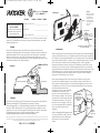
Reinforcing Panel
(Optional)
Figure 2
DS600.2 / DS650.2 / DS680.2
Models:
Authorized Kicker Dealer:
Congratulations on your
KICKER purchase
Door Body
Door Panel
_________________________
Speaker cut-out
Please record your purchase
information and keep your sales
receipt for validation of warranty.
Purchase Date:
_________________________
Speaker Grille
Speaker Model Number:
_________________________
Speaker cut-out
Screws
Your DS components were specially designed for “Livin’ Loud” out in the harsh automotive
environment. They are made of advanced materials and construction techniques to
maintain optimal performance for years to come.
Place Speaker Grille over the Midrange/Woofer
Driver and mount with the enclosed Screws
Application
INSTALLATION
Midrange/Woofer
Driver
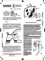
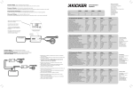
WooferMounting
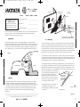
The Kicker DS component systems are specifically designed for mounting in free-air
applications. The speakers do not require a sealed enclosure for optimum performance. It is
important to isolate the sound coming off the front of the driver from the sound radiating
from the back of the driver. This isolation is usually accomplished by using the driver in a
factory speaker location, or in a location with a semi-isolated rear chamber. See Figure 1.
Figure 1
Front Sound
Waves
If you are replacing factory speakers in their original locations, you may have to enlarge the
speaker cut-outs and pre-drill new screw holes using a 7/64” (2.5mm) bit. Custom mounting
locations will require more preparation and work. In either case, make sure the speaker will
not interfere with the trunk and door opening and closing mechanisms, and the enclosed
screws will not puncture the fuel tank, wiring, or interfere with any other mechanical parts on
the underside of the mounting surface. Cycle the windows all the way down and up.
If the speaker cut-out locations require you to cut metal, avoid structural metal and braces.
If the door body and panel cannot support the weight of the speaker, an optional reinforcing
panel (thin piece of wood or Medium Density Fiberboard) may be sandwiched between the
panels. Mount the speaker to the vehicle as outlined in Figure 2.
DS Component Driver
INSTALLATION
Trunk / Storage Space
Rear Sound
Waves
Rear Seat
Location
The sound produced by the DS components is directional, particularly for the tweeter’s
sonic output. The external crossover has a High Frequency Output Attenuation switch
(0, 3 & 6dB) that allows for added flexibility in positioning the tweeter. Find the best location
for stereophonic sound. If necessary, add more DS component systems to the audio
system to help distribute and balance the sound. After determining the best mounting
locations, carefully check the areas where the mounting hardware will be placed.
See Figure 2.
Note: All specifications and performance figures are subject to change. Please visit the www.kicker.com for the most current information.
To get the best performance from your new Kicker speakers, we recommend using genuine Kicker Accessories and Wiring.
Please allow two weeks of break-in time for the speaker to reach optimum performance.
2
DSCOMPONENTSYSTEM
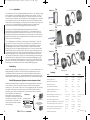
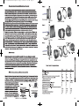
If factory speaker wiring is not available in your desired location, it may be necessary to run
the supplied wire through the door jamb. The speaker wire should be kept away from sharp
edges and avoid the possibility of getting pinched by the door. An existing grommet in the
door jamb is the ideal place to run the speaker wire. If the factory hole and grommet do not
exist or are inaccessible, you must drill a hole
to run the speaker wire through the door jam.
Front Door Body
Be careful not to drill into other wiring or
Stagger the holes for
Front Dash
exiting door mechanisms. Any time a wire is
the wiring and use a
run through a hole, it is necessary to insert a
rubber or plastic
grommet to protect
rubber or plastic grommet to protect the wire
the wire from damage
from damage as outlined in Figure 3.
If the supplied hardware is not applicable to
your installation, some other means of
securely attaching the speakers to the vehicle
must be used.
Speaker
cut-out
Kick Panel
To the
external
crossover
To speaker terminals
Figure 3
3
2007 DS Components Multilingual a01.qxp
11/12/2008
3:47 PM
Page 3
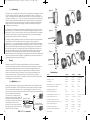
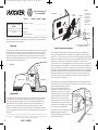
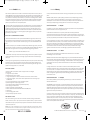
TweeterMounting
Figure 5
INSTALLATION
The tweeter can be mounted one of three ways: flush, angled-surface and angled mounting.
For flush mounting applications, please refer to the illustration in Figure 5. Choose a flat
location on the panel with space behind the panel to allow room for the mounting nut. After
checking the clearances, cut a 1 9/16” (4cm) diameter mounting hole in the panel. Place the
shorter mounting nut behind the panel (only use the longer mounting nut if panel thickness
prohibits the use of the shorter mounting nut). Feed the wire through the optional tweeter
flange, the hole in the panel and the mounting nut. Mount the tweeter by screwing the
mounting nut onto the tweeter.
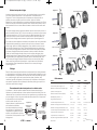
For angled-surface mounting applications use the angled-surface mount cup as a template
and pre-drill one 7/64” (2.5mm) screw hole for attaching the angled-mounting cup to the
panel, and a 5/16” (8mm) hole for the wires. A M3 pan-cross head wood screw is supplied
to attach the mounting cup to the panel. Position the tweeter over the attached angledmounting cup and press it into position. See Figure 6.
For angled mounting applications choose a flat location on the panel with space behind the
panel to allow room for the mounting nut and back angle ring. After checking the
clearances, cut a 1 9/16” (4cm) diameter mounting hole in the panel. Place the front angle
ring (does not fit through the longer tweeter mounting nut) in front of the panel. Then place
the wire and tweeter through the tweeter flange, front angle ring and into the panel. Next
place the wire through the back angle ring (fits through the longer tweeter mounting nut),
place the back angle ring over the rear of the tweeter, and line-up the narrow part of the
front angle ring for the preferred angle of operation. Place the wire through the longer
tweeter mounting nut and loosely tighten the mounting nut around the tweeter. Rotate all the
parts in unison until the tweeter is angled in the desired direction. Secure the assembly by
tightening the tweeter mounting nut. See Figure 7.
Optional Tweeter Flange
Tweeter
Flush Mount
Shorter Mounting Nut
Panel
Tweeter
Figure 6
M3 Screw
Angled-Surface Mount
Angled-Surface Mount Cup
Panel
Tweeter Flange
Figure 7
Back Angle Ring
Wiring
Tweeter
WiringMultipleSpeakers
Modern high performance component system speakers have a lower DC Resistance than
what used to be available. The Kicker DS-Series component system speakers are rated at
four ohms and work with any source unit or amplifier designed to operate at a four ohm
load. If you want to use two DS-Series component system speakers (two midrange/woofers
and two tweeters) on each channel of
Figure 4
your source unit or amplifier wire the
speakers in series, as shown below. This
External Crossover
will improve the sound quality, lower the Source Unit or Amplifier
total harmonic distortion and lessen the
thermal load at the source unit or
High Frequency Output
Attenuation Switch: 0, 3 & 6dB
amplifier. This may prevent an amplifier
Two DS-Series Component
from shutting down, due to over-current
Speakers wired in series to
a single channel
protection circuitry. See Figure 4.
4
DSCOMPONENTSYSTEM
Angled Mount
Front Angle Ring
Panel
Longer Mounting Nut
Performance
Model:
DS600.2
DS650.2
DS680.2
Woofer Size, in (mm)
6 (160)
6.5 (165)
6x8 (160x200)
Tweeter Size, in (mm)
3/4 (20)
3/4 (20)
3/4 (20)
Dome Material
Titanium
Titanium
Titanium
Rated Impedance, ohm (DC Resistance, ohm)
4 (3)
4 (3)
4 (3)
Power Handling Watts, Peak (RMS)
120 (60)
120 (60)
90 (45)
Sensitivity [SPLo], dB @ 1W, 1m
90
90
90
Effective Frequency Range, Hz
35-21k
35-21k
40-21k
Woofer Mounting Hole Diameter, in (cm)
4 13/16 (12.3)
5 1/2 (14)
5x7 3/16 (12.7x18.3)
Woofer Top Mount Depth, in (cm)
1 7/8 (4.8)
1 13/16 (4.6)
2 3/8 (6)
Woofer Bottom Mount Depth, in (cm)
2 3/16 (5.5)
2 (5.1)
2 3/4 (7)
Flush Mounting Tweeter Hole Diameter, in (cm)
1 9/16 (4)
1 9/16 (4)
1 9/16 (4)
High Pass, dB, at Frequency, Hz
12, 4000
12, 4000
12, 4000
Low Pass, dB, at Frequency, Hz
12, 4000
12, 4000
12, 4000
High Frequency Output Attenuation, dB
0, 3 & 6
0, 3 & 6
0, 3 & 6
Bolt-Thru Grilles
Yes
Yes
No
PERFORMANCE
Hooking up the Kicker DS-Series Component Speakers is easy. Mount the external
crossover in a location free and clear of water and mechanical components of the vehicle
with the enclosed phillips-head wood screws. The positive and negative leads on the
speakers are terminated with connectors of different shapes and sizes that intuitively
connect to the external crossover’s connectors. After connecting the speakers to the
external crossover, connect the external crossover to the source unit or amplifier in
accordance with its owner’s manual. For reference, the Gray wire is Positive and the Black
wire is Negative on the external crossover.
5
2007 DS Components Multilingual a01.qxp
11/12/2008
3:47 PM
Page 4
DSSistemasComponentes
ManualdelPropietaro
Por favor registre su información de compra
y mantenga su recibo de ventas para
validación de la garantía.
Cuerpo de la puerta
Panel de
refuerzo (opcional)
DS600.2 / DS650.2 / DS680.2
Modelos:
¡Felicidades por su
compra de KICKER
Garantía
Figura 2
Distribuidor autorizado de Kicker:
_________________________
Fecha de compra:
_________________________
Panel de
la puerta
Hueco de
montaje
Comuníquese con su
concesionario o
distribuidor Kicker
internacional para
obtener infor ación
sobre procedimientos
específicos
relacionados con las
normas de garantía
de su país.
Rejilla
Número de modelo de Altavoz:
_________________________
Hueco de
montaje
Coloque la rejilla sobre el altavoz y el monte
con los tornillos
Aplicación
INSTALACIÓN
Su DS sistemas de componentes se diseñó para “Livin’ Loud” en el ambiente automotor
duro. Utiliza las técnicas avanzadas de materias y construcción para mantener el
desempeño que óptimo para años para venir.
Tornillos
DS altavoz de
frecuencias medias
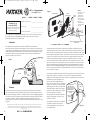
Montajedelaltavozdefrecuenciasmedias
Sus sistemas de componentes de la serie DS de KICKER han sido diseñados
específicamente para montarlos en aplicaciones al aire libre. A pesar de que los altavoces
no necesitan una caja sellada para un rendimiento óptimo, es importante separar el sonido
radiado por delante del sonido radiado por detrás del excitador. Esta separación se logra
normalmente usando un excitador de tamaño correcto en un lugar preestablecido de
fábrica para el altavoz. Vea la Figura 1.
Figura 1
Onda
acústica
DS altavoz de frecuencias medias
INSTALACIÓN
Cajuela
Onda
trasera
Cojin
Posisiton
El sonido producido por los sistemas componentes del DS es direccional. Encuentre el
mejor posisition para el sonido estereofónico. El paso externo tiene una Alta Frencuencia
interruptor de salida de Atenuación (0, 3 & 6dB) eso tiene en cuenta la flexibilidad agregada
a posicionar el altavoz. Si necesario, agrega más sistemas componentes del DS al sistema
para ayudar a distribuir y equilibrar la sano-etapa. Después que determinar el mejor
posistions que monta, verifica con cuidado las áreas donde el hardware que monta irá. Vea
la Figura 2.
Todas las especificaciones y rendimiento de las cifras están sujetos a cambios. Por favor visite www.kicker.com para obtener la
información más reciente. Para obtener el mejor rendimiento de su nuevo altavoz Kicker, recomendamos usar accesorios
y cableado genuinos de Kicker. Deje pasar aproximadamente dos semanas para que el altavoces Componente del DS logre su
rendimiento óptimo.
6
DSSISTEMASCOMPONENTES
Si usted reemplaza los altavoces en las ubicaciones originales, usted puede tener que
ampliar el altavoz que monta hoyos y taladra nuevos hoyos del tornillo que utilizan un 7/64”
(2.5mm) el pedacito. Si desea montar los altavoces de frecuencias medias de la serie DS de
Kicker en lugares especiales en la puerta, evite interferir con los mecanismos de bloqueo de
la puerta y de la ventana. El primer paso es encontrar un lugar del panel de la puerta que
acepte el tamaño del altavoz escogido. Luego quite el panel de la puerta y vea si hay
obstrucción del funcionamiento de la ventana; suba y baje completamente el vidrio. Si hay
que cortar metal para montar los altavoces, evite cortar los refuerzos o el metal estructural.
Puede ser necesario agregar un panel de refuerzo opcional (pedazo delgado de madera o
Plancha de Fibra de Densidad Media {Medium Density Fiberboard, MDF}) si el panel de la
puerta no soporta el peso del altavoz. Monte el altavoz en el panel y el cuerpo de la puerta
como se indica en la Figura 2.
Si no dispone de cableado de fábrica para altavoces de puerta, será necesario encaminar el
cable que se suministra a través del marco de la puerta. Este cable debe mantenerse
alejado de los bordes afilados de la puerta, para que no se pueda apretar por accidente. La
arandela de goma que pueda haber en el
marco de la puerta es el lugar ideal para
Cuerpo de la
hacer pasar los cables. Si no hay tal arandela
puerta
Cuando haga pasar un
Tablero de
de goma, o la que hay no es accesible, debe
cable a través de un
mando
taladrar agujeros para hacer pasar los cables.
agujero en el metal, es
necesario insertar una
Tenga cuidado de no taladrar otros cables o
arandela de plástico o
mecanismos. Cuando haga pasar un cable a
de goma para proteger
el cable
través de un agujero en el metal, es
necesario insertar una arandela de plástico o
Hueco de
Al paso
de goma para proteger el cable, como se
montaje
externo
muestra en la Figura 3.
Si el hardware suministrado no es aplicable a
su instalación, algunos otros medios de
conectar seguramente a los oradores a la
nave se debe utilizar.
Al altavoz
Figura 3
7
2007 DS Components Multilingual a01.qxp
11/12/2008
3:47 PM
Page 5
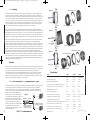
TweeterMontaje
INSTALACIÓN
El altavoz se puede montar uno de tres maneras: limpía, la superficie y montar angulado. Para
aplicaciones de montar de limpíe, se refiere por favor a la ilustración en la Figura 5. Escoja una
ubicación plana en el panel con el espacio detrás del panel para permitir el espacio para la tuerca
que monta. Después que verificar los espacios libres, cortan el diámetro 1 9/16” (4cm) de hoyo
que monta en el panel. Coloque la tuerca más corta que monta detrás del panel. Sólo utilice la
tuerca más larga que monta si el espesor de entrepaño prohibe el uso de la tuerca más corta
que monta. Alimente el cable por el reborde opcional de tweeter, el hoyo en el panel y la tuerca
que montan. Monte el tweeter enroscando la tuerca que monta en el tweeter.
Para aplicaciones de montar de angulado-superficie utiliza la copa de angulado-superficie del
monte como una plantilla y pre-taladro dos 7/64” (2.5mm) hoyos de tornillo para conectar la copa
de angulado-superficie del monte al panel, y un 5/16” (8mm) hoyo para los cables del altavoz. Un
M3 tornillo se suministran para conectar la copa de superficie del monte al panel. Posicione el
tweeter sobre la copa de angulado-superficie del monte y lo aprieta en posición. Vea la Figura 6.
Para montar angulado las aplicaciones escogen una ubicación plana en el panel con el espacio
detrás del panel para permitir el espacio para la tuerca que monta y el anillo del ángulo de
espalda. Después que verificar los espacios libres, cortan el diámetro 1 9/16" (4cm) de hoyo que
monta en el panel. Coloque el anillo anterior del ángulo (no queda por el tweeter más largo que
monta tuerca) delante del panel. Coloque el cable del altavoz y el tweeter por el anillo anterior del
ángulo y en el panel. Coloque el cable del altavoz por el anillo del ángulo de espalda (los ataques
por el tweeter más largo que monta tuerca), coloca el anillo del ángulo de espalda sobre el
trasero del tweeter, y de la alineación la parte estrecha del anillo anterior del ángulo para el ángulo
preferido de la operación. Coloque el cable del altavoz por el tweeter más largo que monta tuerca
y aprieta flojamente la tuerca que monta alrededor del tweeter. Gire todas las partes al unísono
hasta que el tweeter esté angulado en la dirección deseada. Asegure la asamblea apretando el
tweeter que monta tuerca. Vea la Figura 7.
Figura 5
Reborde de tweeter (opcional)
Tweeter
Montar limpíe
Tuerca más corta que monta
Panel
Tweeter
Figura 6
M3 Tornillo
Angulado- superficie
montar
Copa de angulado-superficie del monte
Panel
Reborde de tweeter (opcional)
Figura 7
Anillo del ángulo de espalda
Tweeter
Cabelado
Montar angulado
Cableadodedosaltavocessistemascomponentesaunsolocanal
Los altavoces sistemas componentes modernos de alto rendimiento tienen menor resistencia de
CC que la que había antes. Los altavoces de la serie DS de Kicker tienen una impedancia
nominal de 4 ohmios y funcionan con cualquier unidad fuente o amplificador diseñado para
operar con una carga de 4 ohmios. Si desea usar dos altavoces sistemas componentes (dos
altavoces de frecuencias medias e dos
tweeters) de la serie DS en cada canal de
Figura 4
su unidad fuente o amplificador, conecte los
altavoces en serie, tal como se muestra
Unidad fuente o amplificador
Paso externo
abajo. Esto mejorará la calidad del sonido,
reducirá la distorsión armónica total y
Alta Frencuencia interruptor
aliviará la carga térmica en la unidad fuente
de Atenuación (0, 3 & 6dB)
o amplificador. Esto puede prevenir un
Dos DS altavoces sistemas
componentes conectaron
amplificador de apagar, debido a la red de
en la serie a un solo canal
circuitos de protección.
8
DSSISTEMASCOMPONENTES
Anillo anterior del ángulo
Panel
Tuerca más larga que monta
Rendimiento
Modelo:
DS600.2
DS650.2
DS680.2
Tamaño del woofer, plg (cm)
6 (160)
6.5 (165)
6x8 (160x200)
Tamaño del tweeter, plg (cm)
3/4 (20)
3/4 (20)
3/4 (20)
Material del diafragma del tweeter
Titanio
Titanio
Titanio
Impedancia nominal, ohmio (Resistencia de CC, ohmio)
4 (3)
4 (3)
4 (3)
Procesamiento máximo de potencia, vatios (RMS)
120 (60)
120 (60)
90 (45)
Sensibilidad [SPLo], dB @ 1W, 1m
90
90
90
Gama efectiva de frecuencias, Hz
35-21k
35-21k
40-21k
Diámetro del agujero de montaje, plg (cm)
4 13/16 (12.3)
5 1/2 (14)
5x7 3/16 (12.7x18.3)
Profundidad de montaje superior, plg (cm)
1 7/8 (4.8)
1 13/16 (4.6)
2 3/8 (6)
Profundidad de montaje inferior, plg (cm)
2 3/16 (5.5)
2 (5.1)
2 3/4 (7)
Limpíe Montar el Diámetro del agujero de tweeter, plg (cm) 1 9/16 (4)
1 9/16 (4)
1 9/16 (4)
Paso alto, dB por octava, en la Frecuencia, Hz
12, 4000
12, 4000
12, 4000
Paso bajo, dB por octava, en la Frecuencia, Hz
12, 4000
12, 4000
12, 4000
Alta Frencuencia interruptor de Atenuación, dB
0, 3 & 6
0, 3 & 6
0, 3 & 6
Rejillas de cierra-por
Sí
Sí
No
07192007+07DS
RENDIMIENTO
Es fácil conectar los cables suministrados a los Altavoces de la serie DS de Kicker. Monte el paso
externo en una ubicación libre de agua y componentes mecánicos del vehículo con los tornillos
encerrados. Los conectores positivos y negativos en los altavoces son terminados con
conectores de las formas y los tamaño diferentes que conectan a los conectores externos del
paso. Después de que conectar los altavoces al paso externo, conecten el paso externo a la
unidad fuente o el amplificador de acuerdo con su manual. Para la referencia, el alambre gris es
positivo y el alambre negro es negativo en el paso externo.
9
2007 DS Components Multilingual a01.qxp
11/12/2008
3:47 PM
Page 6
DSKomponenten-Systeme
BenutzerHandBuch
Bitte heben sie für Ihre Garantie den
Kassenzettel auf und tragen Sie die
Daten Ihres Einkaufs ein.
Türkörper
Verstärkungsplatte
(Sonderausstattung)
DS600.2 / DS650.2 / DS680.2
Modelle:
Herzlichen Glückwunsch zum
Kauf des KICKER
Garantie
Abbildung 2
Authorisierter KICKER Händler:
Türfüllung
_________________________
Montageloch
Nehmen Sie mit Ihren
internationalen KickerFachhändler oder
Vertrieb Kontakt auf,
um Details über die
Garantieleistungen in
Ihrem Land zu
erfahren.
_________________________
Einkaufsdatum:
Lautsprechergrill
Lautsprecher Modell Nummer:
_________________________
Montageloch
Schrauben
Ihr DS Komponenten System wurde besonders für “Livin’ Loud” in der harten Autoumwelt
entworfen. Es ist Materialien und Konstruktion fortgeschritten beizubehalten, dass ideale
Leistung jahrelang kommt.
Schrauben Sie den Lautsprechergrill auf mit
den versorgten Schrauben.
Einbau
Das Kicker Komponenten System der DS-Serie ist speziell für den Einbau in nicht
geschlossenen Gehäusen gedacht. Die Lautsprecher benötigen für optimale Leistung kein
geschlossenes Gehäuse. Es ist wichtig, den vorne aus dem Lautsprecher austretenden
Schall vom Schall zu trennen, der von der Rückseite des Lautsprechers kommt. Diese
Trennung wird meist durch die Verwendung der korrekten Treibergröße und Einbau an einer
isolierten hinteren Stelle erreicht. Siehe Abbildung 1.
Abbildung 1
Vordere
Schallwelle
INSTALLATION
DS Komponenten
System
Installation
Wenn Sie Lautsprecher in ihren ursprünglichen Orten ersetzen, dürfen Sie das Montageloch
und neue Schraubenlöcher auf 2,5mm vergrößern. Wenn Sie Ihre Komponten Lautsprecher
der DS-Serie an von Ihnen gewählten Stellen in der Tür einbauen wollen, müssen Sie darauf
achten, dass Sie keine Probleme mit Fenster- und Türschließmechanismen haben. Der erste
Schritt besteht darin, eine Stelle in der Türverkleidung zu finden, in die der gewählte
Lautsprecher hineinpasst. Entfernen Sie dann die Türverkleidung und testen Sie, wie weit
das Fenster nach oben und unten geht. Falls Metall geschnitten werden muss, sollten Sie
tragendes Metall und Verstrebungen vermeiden. Wenn das Gewicht der Lautsprecher für die
Türverkleidung zu hoch ist, kann es nötig sein, eine optionale Verstärkungsplatte (dünne
Holz- oder Faserplatte) einzubauen. Montieren Sie den Lautsprecher wie in Abbildung 2
gezeigt an der Türverkleidung und am Türkörper.
DS Komponenten System
INSTALLATION
Kofferraum / Speicherplatz
Hintere
Schallwelle
Hinterer Sitzplatz
Position
Die Position und Ausrichtung Ihres DS Komponenten Systems beeinflusst die Qualität und
Quantität der Wiedergabe. Die Überkreuzung hat einen Hohen Frequenz
Abschwächungsschalter (0, 3 & 6dB) das hinzufügt Flexibilität bei der Positionierung des
Hochtöners. Finden Sie den besten Ort für stereofonischen Klang. Installieren von mehr
Lautsprechern zum Auto verteilt und gleicht die Räumlichkeit aus. Nachdem Sie die beste
Einbauposition gewählt haben, prüfen Sie sorgfältig die Stellen, an denen
Montagehalterungen angebracht werden sollen. Siehe Abbildung 2.
Änderungen an Spezifikationen und Leistungswerten vorbehalten. Sie finden die aktuellsten Informationen bei kicker.com. Nach etwa zwei
Wochen erreicht der Lautsprecher die optimale Bassleistung. Um die besten Ergebnisse zu erzielen, benutzen Sie nur Originalzubehörteile
und Kabel von KICKER. Änderungen an Spezifikationen und Leistungswerten vorbehalten.
10
DSKOMPONENTENSYSTEM
Wenn keine werksseitigen Kabel für den Anschluss der Lautsprecher verfügbar sind,
müssen Sie das mitgelieferte Kabel durch den Türpfosten verlegen. Dabei ist darauf zu
achten, dass das Lautsprecherkabel von scharfen Kanten ferngehalten und nicht von der
Tür eingeklemmt wird. Eine im Türpfosten vorhandene Schutztülle wäre für die Verlegung
des Lautsprecherkabels ideal. Wenn
werkseitig kein Loch bzw. keine Schutztülle
Türkörper
vorhanden sind, müssen Sie ein Loch
Schwanken Sie die
bohren, um das Lautsprecherkabel durch
Armaturenbrett
Löcher für die Kabel und
den Türpfosten zu verlegen. Dabei ist darauf
benutzen Sie eine
Schutztülle, die Kabel
zu achten, dass Sie nicht andere Kabel oder
von Schaden zu
Türmechanismen anbohren. Wenn Sie ein
schützen.
Kabel durch ein Loch verlegen, müssen Sie
zum Schutz des Kabels eine Schutztülle aus
Montageloch
Gummi oder Plastik einführen. Siehe
Stehblech
Abbildung 3.
Zu den
Lautsprechernterminalen
Wenn die beiliegenden Befestigungselemente
nicht für Ihre Installation passen, muss eine
andere Methode zur sicheren Befestigung
des Systems am Fahrzeug verwendet
werden.
Kabel zur
äußerlichen
Überkreuzung
Abbildung 3
11
2007 DS Components Multilingual a01.qxp
11/12/2008
3:47 PM
Page 7
HochtönerInstallation
Abbildung 5
INSTALLATION
Der Hochtöner kann Ein von drei Wegen aufgestellt werden: flach mit der Oberfläche, winklig
an der Oberfläche und mit Winkelringen an der Oberfläche montiert werden. Für flach mit
der Oberfläche montiert werden, siehe Abbildung 5. Finden Sie einen flachen Ort auf dem
Unterausschuss mit Platz hinter dem Unterausschuss für die Befestigungsmutter. Schneiden
Sie den passenden Hochtöner Flach-Montageloch-Durchmesser im Unterausschuss (4cm).
Stellen Sie die kürzere Befestigungsmutter hinter den Unterausschuss. Führen Sie den Draht
durch das Loch im Unterausschuss und der Befestigungsmutter zu. Stellen Sie den
Hochtöner durch Schrauben der Befestigungsmutter auf den Hochtöner auf.
Für winklig an der Oberfläche Befestigungsanwendung benutzt die OberflächenUntersatztasse als ein Modellrahmen und vordrill zwei 2,5 mm Schraubenlöcher für die
Oberflächen-Untersatztasse zum Unterausschuss, und einem 8 mm Loch für die Drähte.
Schrauben Sie die Oberflächen-Untersatztasse zum Unterausschuss mit der M3 Schraube.
Stellen Sie den Hochtöner über der winkligen Oberflächen-Untersatztasse ein und drücken
Sie ihn in Position. Siehe Abbildung 6.
Für mit Winkelringen an der Oberfläche montiert werden, siehe Abbildung 7. Finden Sie
einen flachen Ort auf dem Unterausschuss mit Platz hinter dem Unterausschuss für die
Befestigungsmutter und hinteren Winkelring. Schneiden Sie den passenden Hochtöner
Flach-Montageloch-Durchmesser im Unterausschuss (4cm). Stellen Sie den vorderen
Winkelring (er passt durch die längere Befestigungsmutter nicht) vor dem Unterausschuss.
Stellen Sie dann den Draht und den Hochtöner durch den vorderen Winkelring und in den
Unterausschuss. Stellen Sie den Draht durch den hinteren Winkelring (er passt durch die
längere Befestigungsmutter) auf. Stellen Sie den hinteren Winkelring über die Hinterseite
vom Hochtöner, und leinen Sie der enge Teil vom vorderen Winkelring für den bevorzugten
Winkel des Betriebs auf. Stellen Sie den Draht durch die längere Befestigungsmutter auf,
und "locker" festziehen die Befestigungsmutter um den Hochtöner. Drehen Sie alle Teile in
Einklang, bis der Hochtöner in der gewünschten Richtung umgebogen ist. Sichern Sie die
Versammlung durch Festziehen den Hochtöner aufstellend Befestigungsmutter.
Hochtöner
flach mit der
Oberfläche
Unterausschuss
kürzere Befestigungsmutter
Hochtöner
Abbildung 6
M3 Schraube
Winklig an der
Oberfläche
Unterausschuss
Winklig Oberflächen-Untersatztasse
Hochtönering
Abbildung 7
Hinterer Winkelring
Hochtöner
mit Winkelringe an der
Oberfläche
Verkabelung
vorderer Winkelring
Unterausschuss
Zwei DS Komponenten Systeme an einen einzelenen Kanal
Moderne Komponenten Systeme verfügen über einen niedrigeren Gleichstromwiderstand,
als dies früher der Fall war. Die Komponten Systeme der Kicker DS-Serie haben eine
Impedanz von 4 Ohm und sind mit jedem auf 4 Ohm ausgelegten Autoradio oder Verstärker
kompatibel. Wenn Sie zwei Komponenten Systeme der DS-Serie an jeden Kanal Ihres
Autoradios oder Verstärkers anschließen wollen, müssen Sie diese, wie oben gezeigt, in
Reihe anschließen. Dies verbessert die
Abbildung 4
Klangqualität, verringert den Klirrfaktor
und reduziert die thermale Belastung des
äußerliche
Autoradio oder Verstärker
Autoradios oder Verstärkers. Dies kann
Überkreuzung
einen Verstärker von Abschalten, auf
Hoher Frequenz
Grund Schutzstromkreises verhindern.
Abschwächungsschalter:
Siehe Abbildung 4.
0, 3 & 6dB
Zwei DS Komponenten
Systeme an einen einzelenen
Kanal anschließen
DSKOMPONENTENSYSTEM
längere
Befestigungsmutter
Leistung
Modell:
DS600.2
DS650.2
DS680.2
Tieftönergröße, Zoll (cm)
6 (160)
6,5 (165)
6x8 (160x200)
Hochtönergröße, Zoll (cm)
3/4 (20)
3/4 (20)
3/4 (20)
Material der Hochtönermembran
Titan
Titan
Titan
Nennimpedanz [Zn], Ohm
4 (3)
4 (3)
4 (3)
Spitzenbelastbarkeit, Watt (RMS)
120 (60)
120 (60)
90 (45)
Empfindlichkeit [SPLo], dB bei 1 W, 1 m
90
90
90
Effektiver Frequenzbereich, Hz
35-21k
35-21k
40-21k
Tieftöner Montageloch-Durchmesser, Zoll (cm)
4 13/16 (12,3)
5 1/2 (14)
5x7 3/16 (12,7x18,3)
Tieftöner Obermontagetiefe, Zoll (cm)
1 7/8 (4,8)
1 13/16 (4,6)
2 3/8 (6)
Tieftöner Untermontagetiefe, Zoll (cm)
2 3/16 (5,5)
2 (5,1)
2 3/4 (7)
Hochtöner Flach-Montageloch-Durchmesser, Zoll (cm)
1 9/16 (4)
1 9/16 (4)
1 9/16 (4)
Hoher Überkreuzungspunkt, dB, an Frequenz, Hz
12, 4000
12, 4000
12, 4000
Niedriger Überkreuzungspunkt, dB, an Frequenz, Hz
12, 4000
12, 4000
12, 4000
Hoher Frequenz Abschwächungsschalter, dB
0, 3 & 6
0, 3 & 6
0, 3 & 6
Schraube-durch Schutzgitter
Ja
Ja
Nein
06062006+06DS
LEISTUNG
Stellen Sie die Verkabelung und Überkreuzung in einen Ort, der klar von Stehenwasser und
Bewegenbauteilen vom Gefäß ist. Die positive und negative goldene Stecker sind von
verschiedenen Größen und verbinden zu den positiven und negativen Drahtverbindern.
Verbinden Sie das andere Ende vom schweren Messgerätdraht zu Ihrem Verstärker gemäß
seinem Benutzerhandbuch. Das graue Kabel ist positiv und das schwarze Kabel ist negativ.
12
Sonderausstattung Hochtönering
13
2007 DS Components Multilingual a01.qxp
11/12/2008
3:47 PM
Page 8
Manuel d'utilisation des
kits deux voies DS
Modèles :
Garantie
Diagramme 2
Porte
Renfort
(facultatif)
Garniture de
porte
DS600.2 / DS650.2 / DS680.2
Distributeur Kicker agréé :
Félicitations pour votre achat
KICKER
_________________________
Découpe
Prière de registrer vos informations d'achat
et de garder le ticket de caisse pour valider
votre garantie.
Pour connaître les
procédures propres
à la politique de
garantie de votre
pays, contactez
votre revendeur ou
distributeur
International Kicker.
_________________________
Date d'achat :
Grille
Numéro de
modèle du haut-parleur :
_________________________
Découpe
Vis
INSTALLATION
Votre DS kits deux voies a été conçus pour l'environnement automoteur dur. L'haut-parleur
utilise des matériels avancés et les techniques de construction pour maintenir l'exécution
optimale pendant des années pour venir.
Haut-parleur
Placer la grille par-dessus l'haut-parleur et le
mont avec les vis encloses
Application
Monter haut-parleur de graves
Ces haut-parleurs kits deux voies Kicker DS ont été spécialement conçus pour un montage
sans enceinte. Leur fonctionnement optimal ne nécessite pas d'enceinte close, mais il est
important d'isoler le son sortant par l'avant du haut-parleur et le son diffusé à l'arrière du
haut-parleur. En général, cette isolation est obtenue en installant dans un emplacement
standard un haut-parleur de taille adéquate, ou dans un emplacement avec un demi-isolé la
chambre postérieure. Voyez le diagramme 1.
Diagramme 1
Onde avant
Kits deux voies DS
INSTALLATION
Espace de stockage
Onde
arrière
Place postérieure
Emplacement
Le son produit par l'haut-parleur kits deux voies de DS est directionnel, particulièrement
pour la production sonore du tweeter. L'appareil croisé externe a un commutateur hautparleur d'aigus modération de Fréquence (0, 3 & 6 dB) cela ajoute la flexibilité dans la
position du tweeter. Trouver le meilleur emplacement pour le son stéréophonique. Si
nécessaire, ajouter les haut-parleurs kits deux voies de DS au système pour aider
distribuent et équilibrent la son-étape. Après avoir déterminé les emplacements le mieux
montants, soigneusement vérifier les secteurs où le matériel montant sera placé. Voyez le
diagramme 2.
Toutes les caractéristiques techniques et données de fonctionnement sont susceptibles de modifications sans préavis. Pour obtenir les
documents les plus récents, visitez le site kicker.com. Afin de réaliser le meilleur résultat de votre nouveau haut-parleur Kicker, nous vous
conseillons de n'utiliser que des accessoires et câblage authentiques de Kicker.
14
KITSDEUXVOIESDS
Si vous remplacez les haut-parleurs d'usine dans leurs emplacements originaux, vous
pouvez avoir à rendre plus grand le montant trous et entraînez les nouveaux trous de vis
utilisant un 7/64” (2.5mm) le morceau. Coutume monter les emplacements exigeront plus de
préparation et le travail. Si vous souhaitez monter les haut-parleurs kits deux voies DS à des
endroits de votre choix sur les portes, veillez à ne pas gêner le fonctionnement des
mécanismes de vitres et de verrouillage des portes. Commencez par trouver sur la garniture
de porte un emplacement compatible avec la taille du haut-parleur. Puis retirez la garniture
de porte et vérifiez le bon fonctionnement de la vitre sur toute sa course. Si le montage des
haut-parleurs nécessite la découpe de parties métalliques, évitez la structure et les renforts
métalliques. Un panneau de renforcement facultatif (morceau de bois mince ou panneau de
fibres de bois de densité moyenne) peut être nécessaire si le poids du haut-parleur est
excessif pour la garniture de porte. Montez le haut-parleur sur la garniture de porte et la
porte conformément à le diagramme 2.
Si le véhicule ne comporte pas de précâblage d'installation audio, faites passer les fils de
haut-parleurs fournis par les montants de portes. Éloignez ces fils des arêtes vives et évitez
qu'ils ne risquent d'être pincés par la porte.
L'idéal est de faire passer les fils de hautPorte avant
parleur par un passe-fils de montant de porte
Garniture
existant. S'il n'y a pas de trou et passe-fils
Tituber les trous pour
avant
l'installation éléctrique et
accessibles, percez un trou de passage des fils utiliser
un caoutchouc ou
de haut-parleur dans le montant de porte.
un oeillet en plastique
pour protéger le fil des
Veillez à ne pas percer d'autres fils ou les
dommages
mécanismes de portes. Pour faire passer un fil
Découpe
électrique dans un trou, insérez un passe-fils
Vers
en caoutchouc ou en plastique afin de protéger
Panneau
externe
de
seuil
de
appareil
le fil, conformément à le diagramme 3.
Vers les
Si le matériel fourni n'est pas applicable à votre
installation, quelques autres moyens
d'attachant assurément les haut-parleurs au
bateau doivent être utilisés.
terminaux
d'haut-parleur
porte
croisé
Diagramme 3
15
2007 DS Components Multilingual a01.qxp
11/12/2008
3:47 PM
Page 9
Monter haut-parleur d’aigus
INSTALLATION
Le tweeter peut être monté un de trois façons : plat, la surface d’angle, et monter incliné.
Pour monter plates les applications, s'il vous plaît se référer à l'illustration dans le
Diagramme 5. Choisir un emplacement plat sur le panneau avec l'espace derrière le
panneau pour permettre la pièce pour le écrou montant. Après avoir vérifié les
dégagements, couper le diamètre de trou montant approprié dans le panneau (4cm). Placer
le écrou montant plus courte derrière le panneau. Nourrir le câble d'haut-parleur par le trou
dans le panneau et le écrou montant. Monter le tweeter en vissant le écrou montant sur le
tweeter.
Pour surface d’angle monter les applications utilise la tasse de mont de surface comme un
gabarit et entraîne pré-deux 7/64” (2,5mm) les trous de vis pour attacher la surface montant
la tasse au panneau, et un 5/16” (8 mm) le trou pour le câble d'haut-parleur. M3 vis sont
fournies pour attacher la surface montant la tasse au panneau. Disposer le tweeter pardessus la surface d’angle montant la tasse et l'appuie en place. Voyez le diagramme 6.
Pour incliné montant des applications choisissent un emplacement plat sur le panneau avec
l'espace derrière le panneau pour permettre la pièce pour le écrou montant et l'anneau
arrière d'angle. Après avoir vérifié les dégagements, couper le diamètre de trou montant
approprié dans le panneau (4cm). Placer l'anneau d'angle de devant (pas capable par le
écrou montant plus longue) devant le panneau. Placer le câble d'haut-parleur et le tweeter
par l'anneau d'angle de devant et dans le panneau. L'endroit prochain le câble d'hautparleur par l'anneau d'angle arrière (les crises par la noix montant plus longue), placer
l'anneau d'angle arrière par-dessus l'arrière du tweeter, et la file la partie étroite de l'anneau
d'angle de devant pour l'angle préféré d'opération. Placer le câble d'haut-parleur par le
écrou montant plus longue et resserrer lâchement le écrou montant autour du tweeter.
Tourner toutes les parties dans l'unisson jusqu'à ce que le tweeter est incliné dans la
direction désirée. Obtenir l'assemblée en resserrant le écrou montant plus longue.
Voyez le diagramme 7.
Câblage
La bride facultative de tweeter
Tweeter
Monter plat
Le écrou montant plus courte
Panneau
Tweeter
Diagramme 6
M3 vis
Surface monter d’angle
La tasse de mont d’angle
Panneau
La bride de tweeter
Diagramme 7
L'anneau arrière d'angle
Tweeter
Monter incliné
Raccordement de deux haut-parleurs à un chaîne seule
La résistance c.c. des haut-parleurs coaxiaux modernes à hautes performances est
inférieure à ce qui existait auparavant. Les haut-parleurs kits deux voies Kicker DS ont une
résistance de 4 ohms et peuvent fonctionner sur tout appareil source ou amplificateur conçu
pour une charge de 4 ohms. Vous pouvez utiliser deux haut-parleurs DS sur chaque canal
de l'appareil source ou de l'amplificateur
en les raccordant en série, comme
Diagramme 4
indiqué ci-dessous. La qualité sonore est
alors améliorée et la distorsion
Appareil Source ou
Externe appareil
Amplificateur
harmonique totale ainsi que la charge
croisé
thermique vue par l'appareil source ou
Haut-parleur d'aigus
l'amplificateur sont réduites. Ceci peut
modération de Fréquence
commutateur : 0, 3 & 6dB
empêcher un amplificateur de la panne,
Deux haut-parleurs à une
en raison des circuits de protection. Voyez
chaîne seule
le diagramme 4.
KITSDEUXVOIESDS
L'anneau d'angle de devant
Panneau
Le écrou montant plus longue
Performances
Modèles :
DS600.2
DS650.2
DS680.2
Diamètre du haut-parleur de graves, in (cm)
6 (160)
6.5 (165)
6x8 (160x200)
Diamètre du haut-parleur d'aigus, in (cm)
3/4 (20)
3/4 (20)
3/4 (20)
Matériau de la membrane de haut-parleur d'aigus
Titane
Titane
Titane
Impédance nominale [Zn], ohms
4 (3)
4 (3)
4 (3)
Puissance admissible, watts, crête (efficace)
120 (60)
120 (60)
90 (45)
Sensibilité [SPLo], dB @ 1 W, 1 m
90
90
90
Plage de fréquence effective, Hz
35-21k
35-21k
40-21k
Dimensions découpe de woofer, in (cm)
4 13/16 (12,3)
5 1/2 (14)
5x7 3/16 (12,7x18,3)
Profondeur de montage de sommet de woofer, in (cm)
1 7/8 (4,8)
1 13/16 (4,6)
2 3/8 (6)
Profondeur de montage de fond de woofer, in (cm)
2 3/16 (5,5)
2 (5,1)
2 3/4 (7)
Dimensions découpe de Tweeter Montant plat, in (cm)
1 9/16 (4)
1 9/16 (4)
1 9/16 (4)
L'haute passe, dB, à la Fréquence, Hz
12, 4000
12, 4000
12, 4000
La passe basse, dB, à la Fréquence, Hz
12, 4000
12, 4000
12, 4000
Haut-parleur d'aigus modération de Fréquence, dB
0, 3 & 6
0, 3 & 6
0, 3 & 6
Visse-à Grilles
Oui
Oui
Non
06062006+06DS
PERFORMANCES
Placer le câble et externe appareil croisé dans un emplacement éclaircit d'eau permanente
et de composants en mouvement du vaisseau. Les terminaux positifs et négatifs en or sont
de tailles différentes et correspondent aux connecteurs de câble d'haut-parleur appropriés,
en or, positifs et négatifs. Après avoir connecté les haut-parleurs à l'externe croisé,
connectent l'appareil croisé externe à l'unité de source ou l'amplificateur conformément à
son manuel du propriétaire. Pour la référence, le câble d'haut-parleur gris est positif et le
câble d'haut-parleur black est négatif.
16
Diagramme 5
17
2007 DS Components Multilingual a01.qxp
18
11/12/2008
3:47 PM
Page 10
19
2007 DS Components Multilingual a01.qxp
20
11/12/2008
DSCOMPONENTSYSTEM
3:47 PM
Page 11
21
2007 DS Components Multilingual a01.qxp
11/12/2008
3:47 PM
Page 12
WARRANTY
AcousticsLimitedWarranty
InternationalWarranty
Kicker warrants this product to be free from defects in material and workmanship under normal use for a period of
THREE (3) MONTHS from date of original purchase with receipt. When purchased from an Authorized KICKER Dealer
it is warranted for ONE (1) YEAR from date of original purchase with receipt. In all cases you must have the original
receipt. Should service be necessary under this warranty for any reason due to manufacturing defect or malfunction
during the warranty period, Kicker will repair or replace (at its discretion) the defective merchandise with equivalent
merchandise at no charge. Warranty replacements may have cosmetic scratches and blemishes. Discontinued
products may be replaced with more current equivalent products.
Contact your International Kicker dealer or distributor concerning specific procedures for your country's warranty
policies.
This warranty is valid only for the original purchaser and is not extended to owners of the product subsequent to the
original purchaser. Any applicable implied warranties are limited in duration to a period of the express warranty as
provided herein beginning with the date of the original purchase at retail, and no warranties, whether express or
implied, shall apply to this product thereafter. Some states do not allow limitations on implied warranties; therefore
these exclusions may not apply to you. This warranty gives you specific legal rights; however you may have other
rights that vary from state to state.
GARANTÍA INTERNACIONAL
WHAT TO DO IF YOU NEED WARRANTY OR SERVICE
Defective merchandise should be returned to your local Authorized Stillwater Designs (Kicker) Dealer for warranty
service. Assistance in locating an Authorized Dealer can be found at www.kicker.com or by contacting Stillwater
Designs directly. You can confirm that a dealer is authorized by asking to see a current authorized dealer window
decal.
If it becomes necessary for you to return defective merchandise directly to Stillwater Designs (Kicker), call the Kicker
Customer Service Department at (405) 624-8510 for a Return Merchandise Authorization (RMA) number. Package all
defective items in the original container or in a package that will prevent shipping damage, and return to:
WARNING: KICKER products are capable of producing sound levels that can permanently damage your hearing!
Turning up a system to a level that has audible distortion is more damaging to your ears than listening to an
undistorted system at the same volume level. The threshold of pain is always an indicator that the sound level is too
loud and may permanently damage your hearing. Please use common sense when controlling volume.
VersiónEspañol
Comuníquese con su concesionario o distribuidor Kicker internacional para obtener infor ación sobre procedimientos
específicos relacionados con las normas de garantía de su país.
ADVERTENCIA: Los excitadores Kicker son capaces de producir niveles de sonido que pueden dañar
permanentemente el oído. Subir el volumen del sistema hasta un nivel que produzca distorsión es más dañino para el
oído que escuchar un sistema sin distorsión al mismo volumen. El dolor es siempre una indicación de que el sonido es
muy fuerte y que puede dañar permanentemente el oído. Sea precavido cuando controle el volumen.
La frase "combustible para vivir la vida Livin' Loud™ a todo volumen" se refiere al entusiasmo por la vida que la marca
Kicker de estéreos de automóvil representa y a la recomendación a nuestros clientes de que vivan lo mejor posible ("a
todo volumen") en todo sentido. La línea de altavoces y amplificadores Kicker es la mejor del mercado de audio de
automóviles y por lo tanto representa el "combustible" para vivir a todo volumen en el área de "estéreos de automóvil"
de la vida de nuestros clientes. Recomendamos a todos nuestros clientes que obedezcan todas las reglas y
reglamentos locales sobre ruido en cuanto a los niveles legales y apropiados de audición fuera del vehículo.
INTERNATIONALE GARANTIE
DeutscheVersion
Stillwater Designs, 3100 N Husband Road, Stillwater, OK 74075
The RMA number must be clearly marked on the outside of the package. Please return only defective components.
The return of functioning items increases your return freight charges. Non-defective items will be returned freightcollect to you.
Include a copy of the original receipt with the purchase date clearly visible, and a "proof-of-purchase" statement listing
the Customer's name, Dealer's name and invoice number, and product purchased. Warranty expiration on items
without proof-of-purchase will be determined from the type of sale and manufacturing date code. Freight must be
prepaid; items sent freight-collect, or COD, will be refused.
WHAT IS NOT COVERED?
HOW LONG WILL IT TAKE?
Kicker strives to maintain a goal of 24-hour service for all acoustics (subwoofers, midrange and coaxial drivers,
tweeters, crossovers, etc) returns. Delays may be incurred if lack of replacement inventory or parts is encountered.
WARNUNG: KICKER-Treiber können einen Schallpegel erzeugen, der zu permanenten Gehörschäden führen kann!
Wenn Sie ein System auf einen Pegel stellen, der hörbare Verzerrungen erzeugt, schadet das Ihren Ohren mehr, als ein
nicht verzerrtes System auf dem gleichen Lautstärkepegel. Die Schmerzschwelle ist immer eine Anzeige dafür, dass
der Schallpegel zu laut ist und zu permanenten Gehörschäden führen kann. Seien Sie bei der Lautstärkeeinstellung
bitte vernünftig!
Der Slogan "Treibstoff für Livin' Loud" bezieht sich auf die mit den Kicker-Autostereosystemen assoziierte
Lebensfreude und die Tatsache, dass wir unsere Kunden ermutigen, in allen Aspekten ihres Lebens nach dem Besten
("Livin' Loud") zu streben. Die Lautsprecher und Verstärker von Kicker sind auf dem Markt für Auto-Soundsysteme
führend und stellen somit den "Treibstoff" für das Autostereoerlebnis unserer Kunden dar. Wir empfehlen allen unseren
Kunden, sich bezüglich der zugelassenen und passenden Lautstärkepegel außerhalb des Autos an die örtlichen
Lärmvorschriften zu halten.
GARANTIE INTERNATIONALE
VersionFrançaise
Pour connaître les procédures propres à la politique de garantie de votre pays, contactez votre revendeur ou
distributeur International Kicker.
GARANTIE
This warranty is valid only if the product is used for the purpose for which it was designed.
It does not cover:
o Damage due to improper installation
o Subsequent damage to other components
o Damage caused by exposure to moisture, excessive heat, chemical cleaners, and/or UV radiation
o Damage through negligence, misuse, accident or abuse. Repeated returns for the same damage may be
considered abuse
o Any cost or expense related to the removal or reinstallation of product
o Speakers damaged due to amplifier clipping or distortion
o Items previously repaired or modified by any unauthorized repair facility
o Return shipping on non-defective items
o Products with tampered or missing barcode labels
o Products returned without a Return Merchandise Authorization (RMA) number
o Freight Damage
o The cost of shipping product to Kicker
o Service performed by anyone other than Kicker
Nehmen Sie mit Ihren internationalen Kicker-Fachhändler oder Vertrieb Kontakt auf, um Details über die
Garantieleistungen in Ihrem Land zu erfahren.
AVERTISSEMENT: Les haut-parleurs Kicker ont la capacité de produire des niveaux sonores pouvant endommager
l'ouïe de façon irréversible ! L'augmentation du volume d'un système jusqu'à un niveau présentant une distorsion
audible endommage davantage l'ouïe que l'écoute d'un système sans distorsion au même volume. Le seuil de la
douleur est toujours le signe que le niveau sonore est trop élevé et risque d'endommager l'ouïe de façon irréversible.
Réglez le volume en faisant prevue de bon sens !
L'expression " carburant pour vivre plein pot " fait référence au dynamisme de la marque Kicker d'équipements audio
pour véhicules et a pour but d'encourager nos clients à faire le maximum (" vivre plein pot ") dans tous les aspects de
leur vie. Les haut-parleurs et amplificateurs Kicker sont les meilleurs dans le domaine des équipements audio et
représentent donc pour nos client le " carburant pour vivre plein pot " dans l'aspect " installation audio de véhicule "
de leur vie. Nous encourageons tous nos clients à respecter toutes les lois et réglementations locales relatives aux
niveaux sonores acceptables à l'extérieur des véhicules.
Failure to follow these steps may void your warranty. Any questions can be directed to the Kicker Customer Service
Department at (405) 624-8510.
Pro Tip: You are one Kicker Loaded-Subwoofer enclosure, one ZX Mono-Amplifier and a few cables away from a slamm’in
system! The Kicker ZX line of mono-amplifiers make it easy to upgrade to solid bass with your existing or stock source unit.
Please ask your dealer about the Kicker Comp and CompVR Subwoofer upgrades.
22
DSCOMPONENTSYSTEM
P.O. Box 459 • Stillwater, Oklahoma 74076 • U.S.A. • (405) 624-8510
20081112-A+07DS
23