1
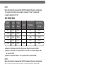
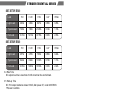
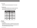
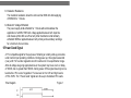
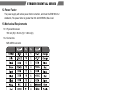
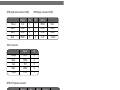
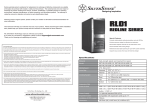
STRIDER ESSENTIAL SERIES
Power for everything you need
SST-ST70F-ESB
SST-ST60F-ESB
High efficiency with 80 PLUS Bronze certification
24/7 continuous power output with 40℃ operating temperature
Class-leading single +12V rail
Multiple protection circuitry
Silent running 120mm fan with 18dBA
PCI-E 8pin and PCI-E 6pin connectors support
ATX 12V 2.3 support
Active PFC
SPECIFICATION
SilverStone Strider Essential
ST70F-ESB
ST60F-ESB
ATX12V 2.3 Switching Power Supply
With Active PFC
80Plus Bronze
PS/2
1.General
1.1Scope
This specification defines the performance characteristics of a single phase
700,600 watts, 5 output power supply. This specification also defines worldwide
safety and electromagnetic compatibility requirements for the power supply
which is intended for use in computer products.
2.Input Characteristics
01
2.1 Input Voltage
Nominal Voltage
--------------------115-230 Vrms
Voltage Variation Range
--------------------------------103.5 - 253 Vrms
2.2 Input Frequency
Nominal Frequency
-----------------------50-60 Hz
Frequency Variation Range
------------------------------------47 Hz to 63 Hz
STRIDER ESSENTIAL SERIES
* The power supply must operate at above frequency with 103.5 - 253VACrms
input voltage range.
2.3 Max. Input AC Current
Max. Input Current
------------------------10A
Measuring Range
-----------------------103.5 - 253 Vrms
2.4 Inrush Current
The power supply must meet inrush requirements for any rated AC voltage,
during turn on at any phase of AC voltage, during a single cycle AC dropout
condition, during repetitive ON/OFF cycling of AC, and over the specified
temperature range. The peak inrush current shall be less than the ratings of
its critical components (including input fuse, bulk rectifiers, and surge limiting
device).
2.5 Efficiency
ST70F-ESB and ST60F-ESB provide an efficiency of 82% when measured at full
load under 115V/60Hz and 230V/50Hz condition.
3.Output characteristics
3.1 Normal Operation Output
SST-ST70F-ESB:
Output
Load
Range
Voltage
MIN
MAX
1. +5V
0.2A
22.0A
±5%
50mV
2. +3.3V
0.1A
22.0A
±5%
50mV
3. +12V
0.6A
52.5A
±5%
120mV
4. -12V
0.0A
0.3A
±10%
120mV
5. +5Vs
0.0A
2.5A
±5%
50mV
Peak
3.5A
Regulation
Ripple & Noise
P-P Max.
Maximum continuous total DC output power should not exceed 700W.
Maximum continuous combined load on +3.3VDC and +5VDC outputs shall
not exceed 130W.
Maximum combined load on 12V outputs shall not exceed 630W.
02
NOTE:
Noise test should be measured with 20 MHz bandwidth frequency oscilloscope.
The output terminal shall add a tantalum capacitor of 10uF in parallel with
a ceramic capacitor of 0.1uF.
SST-ST60F-ESB:
Output
Load
Range
Voltage
MIN
MAX
1. +5V
0.2A
22.0A
±5%
50mV
2. +3.3V
0.1A
22.0A
±5%
50mV
3. +12V
0.6A
45.0A
±5%
120mV
4. -12V
0.0A
0.3A
±10%
120mV
5. +5Vs
0.0A
2.5A
±5%
50mV
Peak
3.5A
Regulation
Ripple & Noise
P-P Max.
Maximum continuous total DC output power should not exceed 600W.
Maximum continuous combined load on +3.3VDC and +5VDC outputs shall
not exceed 120W.
Maximum combined load on 12V outputs shall not exceed 540W.
NOTE:
Noise test should be measured with 20 MHz bandwidth frequency oscilloscope.
The output terminal shall add a tantalum capacitor of 10uF in parallel with
a ceramic capacitor of 0.1uF.
3.2 Remote On/Off Controlled mode
The PSON# signal is required to remotely turn on/off the power supply, PSON#
is an active low signal that turns on the output power rails. When this is not pulled
low by the system, or left open, the outputs (except the +5VSB) turn off.
This signal is pulled to a standby voltage by a pull-up resistor internal to the
power supply.
TTL level
"H" 2.0 V – 5.25 V
"L" 0.0 V – 1.0 V
3.3 Regulation
The cross regulation defined as follows, the output regulation should be within
the specified range.
03
STRIDER ESSENTIAL SERIES
SST-ST70F-ESB:
Load
+5V
+3.3V
+12V
-12V
+5Vsb
Light Load
2.83A
2.83A
9.47A
0.05A
0.45A
Typical Load
7.06A
7.06A
23.68A
0.14A
1.13A
Full Load
14.13A
14.13A
47.35A
0.27A
2.25A
+5V
+3.3V
+12V
-12V
+5Vsb
Light Load
2.57A
2.57A
7.99A
0.05A
0.44A
Typical Load
6.42A
6.42A
19.97A
0.13A
1.11A
Full Load
12.83A
12.83A
39.93A
0.27A
2.22A
SST-ST60F-ESB:
Load
3.4 Rise Time
DC output rise time is less than 20 mS at nominal line and full load.
3.5 Hold-up Time
DC +5V output maintains at least 16mS ,after power off , under 230V/50Hz
75%Load condition.
3.6 5VSB
5VSB is requierd for the implementation of PS-ON described above. 5VSB is
a standby voltage that may be used to power circuits that require power input
during the powered-down state of all power rails. The 5 VSB pin should deliver
5V ± 5% at a minimum of 2.5 A for PC board circuits to operate. Conversely,
PC board should draw no more than 2.5A maximum form this pin. This power
may be used to operate circuits such as soft power control.
3.7 PG-OK
PG-OK is a power good signal and should be asserted high by power supply
to indicate that the +5 VDC and +3.3 VDC outputs are above the under-voltage
thresholds of the power supply. When this signal is asserted high, there should
be sufficient mains energy stored by the converter to guarantee continuous
power operation within specification. Conversely, when either the +5VDC or
the +3.3VDC output voltage falls below the under-voltage threshold, or when
mains power has been removed for a time sufficiently long so that power supply
operation is no longer guaranteed, PG-OK should be deasserted to a low state.
See Figure 1 for a representation of the timing characteristics of the PG-OK,
PS-ON, and germane power rail signals.
04
3.8 3.3V Sense
A default 3.3V sense line should be implemented pin 13 of the connector.
3.9 Capacitive Load
The power supply should be able to power up and operate normally with the
following capacitances simultaneously present on the DC outputs.
Output
Capacitive load (uF)
+5V
6000
+12V
8000
+3.3V
6000
-12V
350
+5VS
350
4. Protection
4.1 Input Protection
In primary circuit of the power supply , a protected fuse is inserted. Only internal
fault of the power supply will cause the fuse blown. Any overload or short circuit
at DC output will keep from fuse brown or fire hazard.
4.2 Output Protection
4.2.1 Under voltage protection
The +5V/+3.3V DC output are protected against the under voltage condition.
Range value can't be exceed 3.3~3.7V at 5V terminal and 2.0~2.4V at 3.3V.
4.2.2 Over Voltage Protection
The +5V/+12V/+3.3V DC output are protected against the over voltage condition .
Maximum value can't be over 6.5V at 5V terminal and 15.5V at 12V, 4.3V at 3.3V.
4.2.3 Over Power Protection
The power supply can be used electronic circuit to limit the output current against
exceeding 50% of surge output power or protected against excessive power
delivery since short circuit of any output or over total power at high line.
4.2.4 Short Circuit Protection
Short circuit placed on +5V,+12V,+3.3V,-12V will latch off. +5VSB will
auto-recovery.
05
STRIDER ESSENTIAL SERIES
5. Start Stability
5.1 No Load Start
When power is applied to ST70F-ESB and ST60F-ESB with no load connected
or under minimum load connected, neither damage to power supply nor hazards
to users will occur.
5.2 Cold Start
The power supply shall operate properly when first applied at normal input
voltage and or so maximum load after 4 hours storage in 0℃ environment.
6. Environments
6.1 Temperature and Humidity
6.1.1 Operating
Temperature
Relative Humidity
0 to 40℃
20 to 90 %
6.1.2 Storage
Temperature
Relative Humidity
-40 to 70℃
20 to 95 % noncondensing
6.2 Altitude
The power supply can operate normally at any altitude between 0 to 10000 feet.
6.3Vibration and Shock
Sweep and resonance search for each of X,Y,Z, axis at the sweep.
RATE of 1/OCTAVE/Min.
Frequency
Duration
Amplitude
5-55-10 Hz
30 minutes
0.35 mm
7. Conducted EMI
CE , FCC
8. Product Safety
8.1 Safety Requirement
TUV, CUS , CB
8.2 Leakage Current
The AC leakage current is less than 3.5mA when the power supply connect
to 253Vac/50Hz.
06
8.3 Insulation Resistance
The insulation resistance should be not less than 30M ohm after applying
of 500VDC for 1 minute.
8.4 Dielectric Voltage Withstand
The power supply shall withstand for 1 minute without breakdown the
application of a 60Hz 1500V AC voltage applied between both input line
and chassis (20mA DC cut-off current). Main transformer shall similarly
withstand 3000Vac applied between both primary and secondary windings
for a minimum of one minute.
9.Power Good Signal
A TTL compatible signal for the purpose of initiating an orderly start-up procedure
under normal input operating conditions. During power up, this signal is asserted
( low ) until +5V is under regulation and AC reaches min. line specification range.
After all voltage are going appropriate level, the system may have a turn on delay
of 100mS, but no greater than 500mS. During power off the signal should go to low
level before +5V is out of regulation. The low level is 0 to 0.8V and high level is
4.75 to 5.25V. The " Power Good "signal can drive up to 6 standard TTL loads.
Time Diagram
Figure 1
* T1 : Turn on time ( 2 sec. Max.)
* T2 : Rise time ( ≦ 20mS Max.)
* T3 : Power good turn on delay time ( 100 < T3 < 500 mS )
* T4 : Switch on time (0.5 sec. Max.)
* T5 : Power good turn off delay time ( 1.0 mS Min.) PS-ON/OFF
* T6 : Power hold-up time ( 16 mS Min.)
* Power on-off cycle :
When the power supply is turned off for a minimum of 2.0 sec. and turn on again,
the power good signal will be asserted.
10.MTBF
The MTBF of the power should be 100,000 hours min.
11.Harmonics
The product shall meet requirement for EN61000-3-2 & EN61000-3-3 :2003
standard of class D, test at 230Vac 50Hz.
07
STRIDER ESSENTIAL SERIES
12.Power Factor
The power supply with active power factor correction, and meet the EN61000-3-2
standards, The power factor is greater than 0.9 at 230V/50Hz, Max. load.
13.Mechanical Requirements
13.1 Physical Dimension
150 mm (W) × 86 mm (H) × 140mm (D)
13.2 Connectors
M/B 24PIN connector
EPS 12V 8PIN connector
Yellow
Yellow
Yellow
Yellow
Signal
+12V
+12V
+12V
+12V
Pin
5
6
7
8
Pin
1
2
3
4
Signal
COM
COM
COM
COM
Black
Black
Black
Black
ATX 12V 4PIN (4+4PIN EPS 12V in split mode)
Black
Black
Signal
GND
GND
Pin
1
2
Pin
3
4
Signal
+12V
+12V
Yellow
Yellow
08
4PIN peripheral connector (HDD)
Yellow
Black
Black
Red
Signal
+12V
COM
COM
+5VDC
4PIN floppy connector (FDD)
Pin
1
2
3
4
Pin
1
2
3
4
Signal
+5VDC
COM
COM
+12V
Red
Black
Black
Yellow
SATA connector
Orange
Black
Red
Black
Yellow
Signal
Pin
+3.3V
COM
+5V
5
4
3
COM
+12V
2
1
8PIN PCI Express connector
Signal
Pin
Pin
Signal
+12V
+12V
1
2
5
6
COM
COM
Black
Black
+12V
COM
3
4
7
8
COM
COM
Black
Black
Signal
Pin
Pin
Signal
Yellow
+12V
1
4
COM
Black
Yellow
+12V
+12V
2
3
5
6
COM
COM
Black
Black
Yellow
Yellow
Yellow
Black sense1
6PIN PCI Express connector
Yellow
09
STRIDER ESSENTIAL SERIES
Warranty Information
Warranty terms & conditions
1.Product component defects or damages resulted from defective production is covered under warranty. Defects or damages with the following conditions will be fixed
or replaced under SilverStone Technology’s jurisdiction.
a)Usage in accordance with instructions provided in this manual, with no misuse, overuse, or other inappropriate actions.
b)Damage not caused by natural disaster (thunder, fire, earthquake, flood, salt, wind, insect, animals, etc…)
c)Product is not disassembled, modified, or fixed. Components not disassembled or replaced.
d)Warranty mark/stickers are not removed or broken.
Loss or damages resulted from conditions other than ones listed above are not covered under warranty.
2.Under warranty, SilverStone Technology’s maximum liability is limited to the current market value for the product (depreciated value, excluding shipping,handling, and
other fees). SilverStone Technology is not responsible for other damages or loss associated with the use of product.
3.Under warranty, SilverStone Technology is obligated to repair or replace its defective products. Under no circumstances will SilverStone Technology be liable for
damages in connection with the sale, purchase, or use including but not limited to loss of data, loss of business, loss of profits, loss of use of the product or incidental or
consequential damage whether or not foreseeable and whether or not based on breach of warranty, contract or negligence, even if SilverStone Technology has been
advised of the possibility of such damages.
4.Warranty covers only the original purchaser through authorized SilverStone distributors and resellers and is not transferable to a second hand purchaser
5.You must provide sales receipt or invoice with clear indication of purchase date to determine warranty eligibility.
6.If a problem develops during the warranty period, please contact your retailer/reseller/SilverStone authorized distributors or SilverStone http://www.silverstonetek.com
Please note that: (i) You must provide proof of original purchase of the product by a dated itemized receipt; (ii) You shall bear the cost of shipping (or otherwise transporting)
the product to SilverStone authorized distributors. SilverStone authorized distributors will bear the cost of shipping (or otherwise transporting) the product back to you after
completing the warranty service; (iii) Before you send the product, you must be issued a Return Merchandise Authorization (“RMA”) number from SilverStone. Updated warranty
information will be posted on SilverStone’s official website. Please visit http://www.silverstonetek.com for the latest updates.
Additional info & contacts
For North America ([email protected])
SilverStone Technology in North America may repair or replace defective product with refurbished product that is not new but has been functionally tested. Replacement
product will be warranted for remainder of the warranty period or thirty days, whichever is longer. All power supplies should be sent back to the place of purchase if it is
within 30 days of purchase, after 30 days, customers need to initiate RMA procedure with SilverStone Technology in USA by first downloading the “USA RMA form for
end-users” form from the below link and follow its instructions.
For Australia only ([email protected])
Our goods come with guarantees that cannot be excluded under the Australian Consumer Law. You are entitled to a replacement or refund for a major failure and for
compensation for any other reasonably foreseeable loss or damage. You are also entitled to have the goods repaired or replaced if the goods fail to be of acceptable
quality and the failure does not amount to a major failure. Please refer to above “Warranty terms & conditions” for further warranty details.
For Europe ([email protected])
For all other regions ([email protected])
Warranty length
For North America and Australia
All SilverStone retail PSU have from the date of purchase, 3 years limited warranty (some PSU carry a 1 or 5 year warranty)
For further information please visit: http://www.silverstonetek.com
For Europe
All SilverStone retail PSU have from the date of purchase, 3 years limited warranty (some PSU carry a 2 or 5 year warranty)
For further information please visit: http://www.silverstonetek.com
For all other regions
Please contact your local SilverStone authorized dealer or distributors for more information.
Note
SilverStone reserve the right to alter the above warranty information. Please visit http://www.silverstonetek.com for the latest update of the warranty information
10
NO.G11220490