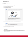
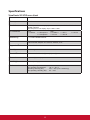
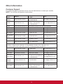
1
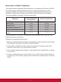
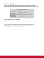
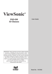
SC-Z55
Zero Client
User Guide
Model No. VS15168


Compliance Information
FCC Statement
This device complies with part 15 of FCC Rules. Operation is subject to the following
two conditions: (1) this device may not cause harmful interference, and (2) this device
must accept any interference received, including interference that may cause undesired
operation.
This equipment has been tested and found to comply with the limits for a Class B digital
device, pursuant to part 15 of the FCC Rules. These limits are designed to provide
reasonable protection against harmful interference in a residential installation. This
equipment generates, uses, and can radiate radio frequency energy, and if not installed
and used in accordance with the instructions, may cause harmful interference to radio
communications. However, there is no guarantee that interference will not occur in a
particular installation. If this equipment does cause harmful interference to radio or
television reception, which can be determined by turning the equipment off and on, the
user is encouraged to try to correct the interference by one or more of the following
measures:
• Reorient or relocate the receiving antenna.
• Increase the separation between the equipment and receiver.
• Connect the equipment into an outlet on a circuit different from that to which the receiver
is connected.
• Consult the dealer or an experienced radio/TV technician for help.
Warning: You are cautioned that changes or modifications not expressly approved by the
party responsible for compliance could void your authority to operate the equipment.
For Canada
• This Class B digital apparatus complies with Canadian CAN ICES-3 (B).
• Cet appareil numérique de la classe B est conforme à la norme NMB-3 (B) du Canada.
Following information is only for EU-member states:
The mark is in compliance with the Waste Electrical and Electronic Equipment
Directive 2002/96/EC (WEEE).
The mark indicates the requirement NOT to dispose the equipment including any
spent or discarded batteries or accumulators as unsorted municipal waste, but
use the return and collection systems available.
If the batteries, accumulators and button cells included with this equipment, display
the chemical symbol Hg, Cd, or Pb, then it means that the battery has a heavy
metal content of more than 0.0005% Mercury or more than, 0.002% Cadmium, or
more than 0.004% Lead.
i


Important Safety Instructions
1. Read these instructions completely before using the equipment.
2. Keep these instructions in a safe place.
3. Heed all warnings.
4. Follow all instructions.
5. Do not use this equipment near water. Warning: To reduce the risk of fire or electric
shock, do not expose this apparatus to rain or moisture.
6. Do not block any ventilation openings. Install the equipment in accordance with the
manufacturer’s instructions.
7. Do not install near any heat sources such as radiators, heat registers, stoves, or other
devices (including amplifiers) that produce heat.
8. Do not attempt to circumvent the safety provisions of the polarized or grounding-type
plug. A polarized plug has two blades with one wider than the other. A grounding
type plug has two blades and a third grounding prong. The wide blade and the third
prong are provided for your safety. If the plug does not fit into your outlet, consult an
electrician for replacement of the outlet.
9. Protect the power cord from being tread upon or pinched, particularly at the plug,
and the point where if emerges from the equipment. Be sure that the power outlet is
located near the equipment so that it is easily accessible.
10. Only use attachments/accessories specified by the manufacturer.
11. Use only with the cart, stand, tripod, bracket, or table specified by the
manufacturer, or sold with the equipment. When a cart is used, use caution
when moving the cart/equipment combination to avoid injury from tipping over.
12. Unplug this equipment when it will be unused for long periods of time.
13. Refer all servicing to qualified service personnel. Service is required when the unit
has been damaged in any way, such as: if the power-supply cord or plug is damaged,
if liquid is spilled onto or objects fall into the unit, if the unit is exposed to rain or
moisture, or if the unit does not operate normally or has been dropped.
14. Do not remove equipment covers and access any of the components inside the
equipment. Any access inside the equipment without an authorized or certified
technician may cause serious injuries and damage. For any problem, contact your
dealer for assistance.
15. Don’t use a keyboard and mouse that in total require more than 200 mA of rated
current during operation.
16. Use only power supplies listed in the user instructions.
ii


Declaration of RoHS Compliance
This product has been designed and manufactured in compliance with Directive 2002/95/
EC of the European Parliament and the Council on restriction of the use of certain
hazardous substances in electrical and electronic equipment (RoHS Directive) and is
deemed to comply with the maximum concentration values issued by the European
Technical Adaptation Committee (TAC) as shown below:
Proposed Maximum
Concentration
Actual Concentration
Lead (Pb)
0.1%
< 0.1%
Mercury (Hg)
0.1%
< 0.1%
Cadmium (Cd)
0.01%
< 0.01%
0.1%
< 0.1%
Polybrominated biphenyls (PBB)
0.1%
< 0.1%
Polybrominated diphenyl ethers
(PBDE)
0.1%
< 0.1%
Substance
Hexavalent Chromium (Cr6+)
Certain components of products as stated above are exempted under the Annex of the
RoHS Directives as noted below:
Examples of exempted components are:
1. Mercury in compact fluorescent lamps not exceeding 5 mg per lamp and in other lamps
not specifically mentioned in the Annex of RoHS Directive.
2. Lead in glass of cathode ray tubes, electronic components, fluorescent tubes, and
electronic ceramic parts (e.g. piezoelectronic devices).
3. Lead in high temperature type solders (i.e. lead-based alloys containing 85% by weight
or more lead).
4. Lead as an allotting element in steel containing up to 0.35% lead by weight, aluminium
containing up to 0.4% lead by weight and as a cooper alloy containing up to 4% lead by
weight.
iii


Copyright Information
Copyright © ViewSonic® Corporation, 2013. All rights reserved.
ViewSonic, the three birds logo, OnView, ViewMatch, ViewMeter, and MultiClient are
either registered trademarks or trademarks of ViewSonic Corporation.
Microsoft®, Windows®, and MultiPoint™ are trademarks of the Microsoft group of
companies.
ENERGY STAR® is a registered trademark of the U.S. Environmental Protection
Agency (EPA). As an ENERGY STAR® partner, ViewSonic Corporation has
determined that this product meets the ENERGY STAR® guidelines for energy
efficiency.
Other product names mentioned herein are used for identification purposes only and may
be trademarks and/or registered trademarks of their respective companies.
Disclaimer: ViewSonic Corporation shall not be liable for technical or editorial errors or
omissions contained herein; nor for incidental or consequential damages resulting from
furnishing this material, or the performance or use of this product.
In the interest of continuing product improvement, ViewSonic Corporation reserves the
right to change product specifications without notice. Information in this document may
change without notice.
No part of this document may be copied, reproduced, or transmitted by any means, for any
purpose without prior written permission from ViewSonic Corporation.
NOTE
• Display Sleep Mode. Within 5 minutes of user inactivity, the display will enter
the Display Sleep mode with a blank screen and reduced power consumption
by the factory default settings. The display returns to the Display Normal mode
upon sensing a request from a user such as moving the mouse or pressing a
key.
• To adjust settings for the Display Sleep mode, click Options > Configuration >
OSD to adjust the settings.
• System Sleep Mode. ViewSonic SC-Z55 doesn’t support the System/Client
Sleep mode.
NOTE
• The default power management settings have been selected for compliance
with ENERGY STAR that are recommended by the ENERGY STAR program for
optimal energy savings.
iv


Product Registration
To meet your future needs, and to receive any additional product information as it
becomes available, please register your product on the Internet at: www.viewsonic.com.
For Your Records
Product Name:
Model Number:
Document Number:
Serial Number:
Purchase Date:
SC-Z55
ViewSonic Zero Client
VS15168
SC-Z55_UG_ENG Rev. 1A 01-02-13
_______________________________
_______________________________
Product disposal at end of product life
ViewSonic respects the environment and is committed to working and living green. Thank
you for being part of Smarter, Greener Computing. Please visit ViewSonic website to learn
more.
USA & Canada: http://www.viewsonic.com/company/green/recycle-program/
Europe: http://www.viewsoniceurope.com/uk/support/recycling-information/
Taiwan: http://recycle.epa.gov.tw/recycle/index2.aspx
v


About This User’s Manual
This installation guide provides basic information on how to set up SC-Z55 zero clients.
Manual Structure and Subjects
Chapter
Subject
1
Provides an overview of ViewSonic SC-Z55 zero clients.
2
Provides detailed instructions on how to set up ViewSonic SC-Z55 zero clients.
Specifications
Provides detailed information on key components of ViewSonic SC-Z55 zero clients.
Notes, Tips, and Warnings
Throughout this manual, the notes and warnings in the following formats are used to provide important
information, and prevent injuries to you, damage to your devices, or loss of data on your system.
NOTE
• A note provides important information for a specific situation.
WARNING
• A warning provides crucial information that must be followed to prevent injuries
to you, damage to your devices, or loss of data on your system.
vi


Table of Contents
Compliance Information i
Important Safety Instructions ii
Declaration of RoHS Compliance iii
Copyright Information iv
Product Registration v
About This User’s Manual vi
Manual Structure and Subjects Notes, Tips, and Warnings vi
vi
1
2
Overview 1
1.1
Introduction 2
1.2
Features 1.3
Package Contents 3
1.4
Exterior Views 3
1.5
Panel Components 4
1.6
LED Indicators 2
6
Setting Up Your SC-Z55 7
2.1
Positioning Your SC-Z55 8
2.2
Assembling the AC Adapter 11
2.3
Getting Connected 12
Specifications 13
Other Information 14
Customer Support 14
Limited Warranty 15
1
Overview
This chapter provides an overview of your SC-Z55 zero clients.
1.1 Introduction
Desktop virtualization and simple endpoint devices
2
1.2 Features
Key features of ViewSonic SC-Z55
2
1.3 Package Contents
Check your package contents
3
1.4 Exterior Views
Overview of zero client outside elements
3
1.5 Panel Components
Descriptions of front and rear panel components
4
1.6 LED Indicators
Descriptions of signals for LED indicators
1
6
Overview
Introduction
1.1 Introduction
Desktop virtualization provides a new perspective to reconsider the design and implementation of an IT
infrastructure. In a desktop virtualization infrastructure, a station is no longer a cumbersome desktop, but simply
an endpoint device for users to access delivery services from the server(s).
With the introduction of the desktop virtualization technologies, you can considerably benefit from:
• On-demand applications/desktops
• Centralized management of work environments
• Drastically reduced endpoint software/hardware issues
• Simplified system maintenance and Improved system security
• More scalability with low-cost endpoint devices
1.2 Features
The key features of ViewSonic SC-Z55 zero clients are:
• Teradici™ TERA2321 processor with Teradici™ 2nd generation zero client chipset
• Support for VMware® desktop virtualization solution: VMware® View™
2
Overview
Package Contents
1.3 Package Contents
Please check your package contents. Ensure that all of the items are present in your package. If any items are
missing or damaged, please contact your dealer immediately.
ViewSonic SC-Z55
ViewSonic SC-Z55
AC adapter
DVI-I to VGA adapter
Stand (VESA plate)
Driver CD
Quick Start Guide
SC-Z55
Zero Client
01/02/13 SC-Z55_CD
Compliance Information
brochure
1.4 Exterior Views
ViewSonic SC-Z55
Left Front View
Right Rear View
Front Panel
Rear Panel
3
Overview
Panel Components
1.5 Panel Components
ViewSonic SC-Z55
1
2
3
4
5
Front Panel
No.
Component
Sign
Name
Description
1
Power LED
2
Power button
3
Microphone port
Connects to a microphone.
4
Headphone port
Connects to a set of headphones or
a speaker system.
5
USB port
4
Indicates the status of power.
• Press to power on the zero client.
• Long press to force power off the zero client.
Connects to a USB device.
Overview
Panel Components
ViewSonic SC-Z55
6
7
8
9
10
Rear Panel
No.
Panel Component
Sign
Component Name
Description
6
DVI-D port
Connects to a high quality digital display
device such as a LCD monitor or
a digital projector.
7
DVI-I port
Connects to a high quality digital display
device such as a LCD monitor or
a digital projector.
8
LAN port
Connects to a network.
9
USB port
Connects to a keyboard or mouse.
10
DC IN
Connects to an AC adapter.
NOTE
• Your SC-Z55 comes with a DVI-I to VGA adapter. If only the VGA monitor is available,
use the supplied DVI-I to VGA adapter to connect your VGA monitor to SC-Z55’s
DVI-I port. For detailed instructions, please see section ”2.3 Getting Connected” on
page 12.
5
Overview
LED Indicators
1.6 LED Indicators
Your SC-Z55 is equipped with a Power LED to indicate the state of power. The meanings of LED signals
are described as follows:
LED
Power LED
Signal
Meaning
Off
The client is off.
Blue
The client is on.
The LAN port of your SC-Z55 has two LED indicators showing the state of networking. The meanings of
LED signals are described as follows:
Left LED
(transmission rate)
LED Signal
Right LED
(transmission activity)
Meaning
Off
Off
Off
Amber blinking
The client is not connected to a LAN.
The client connects to a 10 Mbps LAN.
Orange
Amber blinking
The client connects to a 100 Mbps LAN.
Green
Amber blinking
The client connects to a 1000 Mbps LAN.
6
2
Setting Up Your SC-Z55
This chapter provides detailed instructions on how to set up your
SC-Z55 zero clients.
2.1 Positioning Your SC-Z55
To mount your SC-Z55
Step
Step
Step
Step
Step
1:
2:
3:
4:
5:
Remove the Stand from Your SC-Z55
Understand Your Stand / VESA Mount Kit for SC-Z55
Store Screws inside the Bracket
Remove Screws from the Bracket
Mount Your SC-Z55
8
9
10
10
11
2.2 Assembling the AC Adapter
How to assemble the AC adapter and its detached plug
11
2.3 Getting Connected
How to connect peripherals and power for SC-Z55
7
12
Setting Up Your SC-Z55
Positioning Your SC-Z55
2.1 Positioning Your SC-Z55
There are two ways to position your SC-Z55:
• Put it (with its stand) on a desk or a desired place uprightly.
• Mount it on the back of a monitor using a VESA mount kit.
To mount your SC-Z55 on the back of a monitor, please follow the steps below:
Step 1: Remove the Stand from Your SC-Z55
Step 2: Understand Your Stand / VESA Mount Kit for SC-Z55
Step 3: Store Away Screws inside the Bracket
Step 4: Remove Screws from the Bracket
Step 5: Mount Your SC-Z55
Step 1: Remove the Stand from Your SC-Z55
To remove the stand from your SC-Z55, please do the following:
1. Place your SC-Z55 on a flat surface with the stand side upward.
2. Remove the screw that fixes the stand to your SC-Z55.
3. Store away the removed screw inside the stand. Detailed instructions will be
provided in Step 2 and 3.
NOTE
• It’s highly recommended to store screws away inside the stand when not needed
to prevent them getting lost.
8
JPAA
n
in Taiwa
3A
: +5V / Made
造
/ 输入
輸入造 / 台湾制
Input/
台灣製
Setting Up Your SC-Z55
Positioning Your SC-Z55
Step 2: Understand Your Stand / VESA Mount Kit for SC-Z55
The stand for your SC-Z55 is dual-purpose: it can be used as a stand or as a VESA mount kit. All screws of different
types supplied with the stand / VESA mount kit can be stored away inside the main bracket when not needed.
Screws Stored Away inside the Bracket
The following figure shows different types of screws stored away inside the main bracket.
Dual-purpose
bracket
1
1
2
2
3
Screw Type
Number
Description
1
2
The largest-size screws used to secure the bracket to a monitor as a VESA mount
if the middle-size screws cannot firmly secure the bracket and your SC-Z55 to the
monitor.
2
4
The middle-size screws used to secure the bracket to your SC-Z55 and to a monitor
when using the bracket as a VESA mount.
3
1
The smallest-size screw used to secure the bracket to your SC-Z55 as a stand.
Mount Holes on the Bracket
Refer to the following figure and descriptions for the VESA mount holes on the bracket.
Mount Hole
1
1
2
2
2
2
1
1
Description
1
The VESA mount holes used to secure the bracket to a monitor (only two of them will be used).
2
The VESA mount holes used to secure the bracket to your SC-Z55 (only two of them will be
used).
9
Setting Up Your SC-Z55
Positioning Your SC-Z55
Step 3: Store Screws inside the Bracket
To store screws inside the bracket, please do the following:
NOTE
• It’s highly recommended to store screws inside the bracket when not needed
to prevent them getting lost.
1. Place a sheet of paper or a piece of cloth on a flat surface, and then put your bracket on that paper or cloth
with the screw storage side upward.
2. Place the screw upon its storage space, and push the screw into the space with your finger until it clicks
into place. For the smallest-size screw, use the tip of a screwdriver instead to push the screw.
NOTE
• Please refer to the figure and descriptions in “Step 2: Understand Your Stand / VESA
Mount Kit for SC-Z55”5” for the correct storage space of each screw.
Step 4: Remove Screws from the Bracket
To remove screws stored inside the bracket, please do the following:
1. Place a sheet of paper or a piece of cloth on a flat surface, and then put your bracket on that paper or cloth
with the screw storage side downward.
2. Insert the tip of a screwdriver into the square holes to remove the desired screws from the bracket.
Square Hole
10
Setting Up Your SC-Z55
Assembling the AC Adapter
Step 5: Mount Your SC-Z55
To mount your SC-Z55 on the back of a monitor, please do the following:
1. Refer to Step 2 and Step 4 to prepare required screws for mounting your SC-Z55.
• You will need two (2) screws of type
• You will need two (2) screws of type
2
1
to secure the bracket to your SC-Z55.
or
2
to secure the bracket to the monitor.
2. Place your SC-Z55 on a flat surface with the VESA mount hole side upward.
3. Refer to Step 2 to choose two of the four VESA mount holes on the bracket to align with two mount holes
on your SC-Z55 such that the bracket projects out and is closer to the rear panel than the front one as shown
below, and then secure the bracket to your SC-Z55 with two (2) screws of type 2 .
4. Align the mount holes on the bracket with the mount holes on the back of the monitor, and then secure the
bracket to the monitor with two (2) screws of type 2 or 1 . Ensure that your SC-Z55 is located in the center
of the monitor and the rear panel of your SC-Z55 is facing rightward as shown below.
Have SC-Z55’s rear panel
facing rightward.
2.2 Assembling the AC Adapter
To assemble the AC adapter for your SC-Z55, please do the following:
1. Unpack your zero client package and take out the AC adapter
and its detached plug.
2. Slide the plug into the AC adapter until it clicks into place.
NOTE
• The supplied plug may vary, depending on different areas.
11
Setting Up Your SC-Z55
Getting Connected
2.3 Getting Connected
To make connections for your SC-Z55, please do the following:
1. Connect your SC-Z55 to your local network with an Ethernet cable.
2. Connect a keyboard and mouse to your SC-Z55.
3. Connect and turn on the monitor(s).
NOTE
• For your SC-Z55, if only the VGA monitor is available, use the supplied DVI-I to VGA
adapter to connect your SC-Z55 and monitor.
DVI-I port
(SC-Z55 only)
VGA cable
DVI-I to VGA
adapter
• Please note that you need to connect and turn on your monitor(s) before
powering up your zero client. Otherwise, the client may fail to set
an appropriate resolution for the monitor(s).
4. Connect your SC-Z55 to a power outlet using the AC adapter included in the package.
NOTE
• For detailed instructions on how to assemble the supplied AC adapter, please refer
to section ”2.2 Assembling the AC Adapter” on page 11.
5. Connect other peripherals for your SC-Z55 if needed.
Manual of Zero Client, PCoIP firmware update and PCoIP Management Console Software:
1. Please visit ViewSonic website at www.viewsonic.com to download the user guide of Zero Client and PCoIP
firmware updates.
2. The latest version of “PCoIP Management Console Software” can be downloaded free of charge from the
Teradici web site. You will simply need to create an account first and accept the End User License Agreement
(EULA), before downloading:
http://techsupport.teradici.com/ics/support/default.asp?deptID=15164
12


Specifications
ViewSonic SC-Z55 zero client
Processor
Teradici TERA2321
Memory
512 MB
Resolutions
Two DVI ports for one display: Up to 2560 x 1600, dual DVI-to-DVI Y cable
needed (optional)
One DVI port for one display: Up to 1920 x 1200
I/O interfaces
Front:
2 x USB 2.0
Networking
1 x 10/100/1000Mb Ethernet
Power
DC Power In: DC 5V, 3A
External Power Adapter: AC 100-240, 50/60Hz, 0.5A
1 x Microphone
1 x Headphone
Rear:
2 x USB 2.0
1 x RJ-45
1 x DVI-I
1 x DVI-D
Supported Protocols VMware PCoIP
Security
1 x Kensington lock slot
Mount / Stand
VESA mount kit / Stand, (W)68 x (H)10 x (D)111 mm
Dimensions
(W)39.5 x (H)143 x (D)103 mm
Net Weight
1.15 lbs (0.52 kgs)
Environment
Operating Temperature:0° C ~ 40° C
Non-operating Temperature:
-30° C ~ 60° C
Operating Humidity (Rh):
10% ~ 90% (non-condensing)
Non-operating Humidity (Rh): 5% ~ 95%
13
1 x DC IN
Other Information
Customer Support
For technical support or product service, see the table below or contact your reseller.
NOTE: You will need the product serial number.
Country/
Region
Website
T = Telephone
F = FAX
Email
Australia/New
Zealand
www.viewsonic.com.au
AUS= 1800 880 818
NZ= 0800 008 822
[email protected]
Canada
www.viewsonic.com
T (Toll-Free)= 1-866-463-4775
T (Toll)= 1-424-233-2533
[email protected]
F= 1-909-468-3757
Europe
www.viewsoniceurope.com www.viewsoniceurope.com/uk/support/call-desk/
Hong Kong
www.hk.viewsonic.com
T= 852 3102 2900
[email protected]
India
www.in.viewsonic.com
T= 1800 266 0101
[email protected]
Korea
www.kr.viewsonic.com
T= 080 333 2131
[email protected]
Latin America
(Argentina)
www.viewsonic.com/la/
T= 0800-4441185
[email protected]
Latin America
(Chile)
www.viewsonic.com/la/
T= 1230-020-7975
[email protected]
Latin America
(Columbia)
www.viewsonic.com/la/
T= 01800-9-157235
[email protected]
Latin America
(Mexico)
www.viewsonic.com/la/
T= 001-8882328722
[email protected]
Renta y Datos, 29 SUR 721, COL. LA PAZ, 72160 PUEBLA, PUE. Tel: 01.222.891.55.77 CON 10 LINEAS
Electroser, Av Reforma No. 403Gx39 y 41, 97000 Mérida, Yucatán. Tel: 01.999.925.19.16
Other places please refer to http://www.viewsonic.com/la/soporte/index.htm#Mexico
Latin America
(Peru)
www.viewsonic.com/la/
T= 0800-54565
[email protected]
Macau
www.hk.viewsonic.com
T= 853 2870 0303
[email protected]
Middle East
ap.viewsonic.com/me/
Contact your reseller
[email protected]
Puerto Rico &
Virgin Islands
www.viewsonic.com
T= 1-800-688-6688 (English)
T= 1-866-379-1304 (Spanish)
F= 1-909-468-3757
[email protected]
[email protected]
Singapore/
Malaysia/
Thailand
www.ap.viewsonic.com
T= 65 6461 6044
[email protected]
South Africa
ap.viewsonic.com/za/
Contact your reseller
[email protected]
United States
www.viewsonic.com
T (Toll-Free)= 1-800-688-6688
T (Toll)= 1-424-233-2530
[email protected]
F= 1-909-468-3757
14
Limited Warranty
ViewSonic® Thin Client
What the warranty covers:
ViewSonic warrants its products to be free from defects in material and workmanship during the warranty
period. If a product proves to be defective in material or workmanship during the warranty period, ViewSonic
will, at its sole option, repair or replace the product with a similar product. Replacement Product or parts may
include remanufactured or refurbished parts or components. The replacement unit will be covered by the
balance of the time remaining on the customer’s original limited warranty. ViewSonic provides no warranty
for the third-party software included with the product or installed by the customer.
How long the warranty is effective:
ViewSonic Thin Client products are warranted for (3) years from the first consumer purchase for parts and
labor.
User is responsible for the back up of any data before returning the unit for service. ViewSonic is not
responsible for any data lost.
Who the warranty protects:
This warranty is valid only for the first consumer purchaser.
What the warranty does not cover:
1.Any product on which the serial number has been defaced, modified or removed.
2.Damage, deterioration or malfunction resulting from:
a.Accident, misuse, neglect, fire, water, lightning, or other acts of nature, unauthorized product
modification, or failure to follow instructions supplied with the product.
b. Any damage of the product due to shipment.
c. Removal or installation of the product.
d. Causes external to the product, such as electrical power fluctuations or failure.
e. Use of supplies or parts not meeting ViewSonic’s specifications.
f. Normal wear and tear.
g. Any other cause which does not relate to a product defect.
3.Any product exhibiting a condition commonly known as “image burn-in” which results when a static image
is displayed on the product for an extended period of time.
4. Removal, installation, one way transportation, insurance, and set-up service charges.
How to get service:
1. For information about receiving service under warranty, contact ViewSonic Customer Support (Please
refer to Customer Support page). You will need to provide your product’s serial number.
2. To obtain warranty service, you will be required to provide (a) the original dated sales slip, (b) your name,
(c) your address, (d) a description of the problem, and (e) the serial number of the product.
3. Take or ship the product freight prepaid in the original container to an authorized ViewSonic service center
or ViewSonic.
4. For additional information or the name of the nearest ViewSonic service center, contact ViewSonic.
Limitation of implied warranties:
There are no warranties, express or implied, which extend beyond the description contained herein including
the implied warranty of merchantability and fitness for a particular purpose.
4.3: ViewSonic Thin Client Warranty
Page 1 of 2
15
MC_LW01 Rev. 1a 09-02-11
Exclusion of damages:
ViewSonic’s liability is limited to the cost of repair or replacement of the product. ViewSonic shall not be
liable for:
1. Damage to other property caused by any defects in the product, damages based upon inconvenience,
loss of use of the product, loss of time, loss of profits, loss of business opportunity, loss of goodwill,
interference with business relationships, or other commercial loss, even if advised of the possibility of
such damages.
2. Any other damages, whether incidental, consequential or otherwise.
3. Any claim against the customer by any other party.
4. Repair or attempted repair by anyone not authorized by ViewSonic.
Effect of state law:
This warranty gives you specific legal rights, and you may also have other rights which vary from state
to state. Some states do not allow limitations on implied warranties and/or do not allow the exclusion of
incidental or consequential damages, so the above limitations and exclusions may not apply to you.
Sales outside the U.S.A. and Canada:
For warranty information and service on ViewSonic products sold outside of the U.S.A. and Canada, contact
ViewSonic or your local ViewSonic dealer.
The warranty period for this product in mainland China (Hong Kong, Macao and Taiwan Excluded) is subject
to the terms and conditions of the Maintenance Guarantee Card.
For users in Europe and Russia, full details of warranty provided can be found in www.viewsoniceurope.com
under Support/Warranty Information.
4.3: ViewSonic Thin Client Warranty
Page 2 of 2
16
MC_LW01 Rev. 1a 09-02-11