1
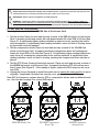
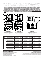
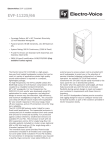
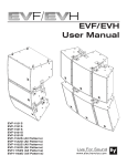
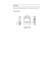
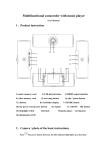
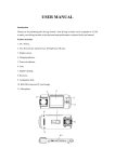
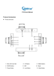
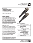
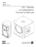
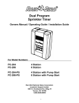
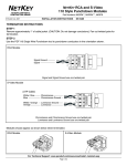
EV-I Access Card
Access Card for Plug-In
Loudspeaker Diagnostics
User Instructions
The Access Card is a unique feature of the EV-Innovation series loudspeaker families. This
simple plug-in device allows diagnostic access to the transducers and protection circuitry
inside the enclosure WITHOUT requiring any disassembly or disconnections beyond simple
removal and replacement of the plug-in switch card. DCR values described in these instructions are typical for EV-I series two-way systems (eg: EVF-1122S/64). For complete modelspecific DCR values, consult the chart on page 4.
Tools Required:
<50.0
#2
1.
#2 Phillips Screwdriver
Instructions:
2.
Ohm Meter capable of accurate
measurements below 50 ohms
1. If applicable, remove screws holding the security cover, gland nut cover, or NL4 cover in
place. Note position of the switch card. The card must be replaced in exactly the same
position as it was originally or system performance will be adversely affected!
2. Carefully remove the switch card and set it aside. Plug the Access Card onto the header in
place of the switch card. Note that the Access Card, unlike the switch card, will only fit in
one position centered on the input cup (See Figure 1).
3. Turn on the Ohm Meter and set it to the low ohms (x1) scale. Short the two probes together and calibrate the meter to “Zero” (See Figure 2). If your meter does not have this calibration feature, note the ohms reading. This is the residual internal resistance of the meter,
probes and test leads. You will need to DEDUCT this number from the results you measure
at the Access Card.
0.0
Figure 1:
Switch Card Removal / Access Card Install
Adjust
Figure 2:
Ohm Meter Calibration
Important! You are testing for DC resistance (DCR). Do not confuse DCR with impedance!
Simple DCR measurements will identify most common failures. Experienced technicians may perform more
sophisticated tests by connecting specialized test gear in place of the ohm meter.
Important! Never connect an amplifier to a PTP test point!
Warning! Compression drivers are easily destroyed by improper testing. Never connect a battery or
other power source directly to a compression driver! Any testing beyond the DCR measurements outlined
here is conducted at your own risk. Drivers destroyed by improper testing are not covered under warranty!
For EVF and EVH 2-way systems:
Use only the test points on the GREEN side of the Access Card
1. Test the woofer: Place one test lead securely on each of the RED test points on the Access
Card. A properly functioning woofer will read approximately 5.0 ohms DCR, ±0.5 ohm (See
Figure 3). A significantly higher reading indicates an open voice coil, meaning the woofer
must be replaced. A significantly lower reading indicates a voice coil that is shorting, meaning the woofer must be replaced.
2. Test the compression driver: Place one test lead securely on each of the YELLOW test
points on the Access Card. A properly functioning compression driver will read approximately 4.3 ohms DCR, ±0.5 ohm (See Figure 4). A significantly higher reading indicates an
open voice coil, meaning the compression driver must be replaced. A significantly lower
reading indicates a voice coil that is shorting, meaning the compression driver must be replaced.
3. Test the PTP (Power Tracking Protection) network: Place one test lead securely on each of
the GREEN test points on the Access Card. A properly functioning PTP will read no more
than 2 ohms (See Figure 5). If the reading is higher, replace the SK-3 lamps on the crossover PCB.
4. Unplug the Access Card and re-install the switch card in exactly the same position it was in
originally. If applicable, Re-attach the security cover, gland nut cover, or NL4 cover.
Note: EVF low-frequency systems have no PTP or compression drivers, and use different woofers. See the chart on page 4 for correct DCR values.
5.0
4.3
1.1
Figure 3:
EVF/EVH Woofer Test
Figure 4:
EVF/EVH Compression
Driver Test
Figure 5:
EVF/EVH Protection
Network Test
For EVA passive full-range systems:
Use only the test points on the BLACK side of the Access Card
Note the position of the HF shading switch card. The card must be replaced in exactly the
same position as it was originally or system performance will be adversely affected!
EVA components are wired in pairs. Therefore, both woofers will be tested together at the
same time, as will the upper HF compression driver pair and the lower HF compression driver
pair. Each HF compression driver pair has its own PTP network and these are also tested
separately. EVA DCR values are referenced to the black (common) test point (See Figure 6).
To directly access transducer pairs for more sophisticated testing, substitute the (-) input connection on the input terminal block for the black (common) test point on the access card (See
Figure 9). Note: DCR values listed are not valid for this connection.
1. Test the woofers: Place one test lead securely on the RED test point and the other on the
BLACK (common) test point on the Access Card. A properly functioning woofer pair will
read approximately 43.2 ohms DCR, ±1 ohm (See Figure 6). A significantly higher reading
indicates one of the woofers has an open voice coil, meaning the woofer needs to be replaced. A significantly lower reading indicates one or both of the woofers has a voice coil
that is shorting, meaning the woofer(s) must be replaced.
2. Test the compression driver pairs: Test the upper compression driver pair by placing one
test lead securely on the UPPER YELLOW test point and the other on the BLACK (common) test point on the Access Card. A properly functioning compression driver pair will
read approximately 41.6 ohms DCR, ±1 ohm (See Figure 7a). A significantly higher reading
indicates one of the compression drivers has an open voice coil, meaning the compression driver(s) must be replaced. A significantly lower reading indicates one or both of the
compression driver voice coils are shorting, meaning the compression driver(s) must be
replaced. Test the lower compression driver pair by repeating the above test with the meter
connected to the LOWER YELLOW test point (See Figure 7b).
43.2
41.6
41.6
Figure 6:
EVA Woofer Pair Test
Figure 7a:
EVA Upper Compression
Driver Pair Test
Figure 7b:
EVA Lower Compression
Driver Pair Test
3. Test the PTP (Power Tracking Protection) networks: Test the PTP network for the UPPER
compression driver pair by placing one test lead securely on the UPPER GREEN test point
and the other on the BLACK (common) test point on the Access Card. A properly functioning PTP will read no more than 46 ohms (See Figure 8a). If the reading is higher, replace
the SK-3 lamps on the crossover PCB. To test the PTP network for the LOWER compression driver pair, repeat the above test using the LOWER GREEN test point (See Figure 8b).
4. Unplug the Access Card and re-install the HF shading switch card in exactly the same position it was in originally. If applicable, re-attach the security cover, gland nut cover, or NL4
cover.
44.7
44.7
Figure 8a:
EVA Upper Protection
Network Test
Figure 8b:
EVA Lower Protection
Network Test
Figure 9:
EVA Direct Access for
Transducer Pairs
Series
Model
Woofers
DCR Value
Compression Drivers
DCR Value
PTP Network
DCR Value
EVA
EVA-2082S
(All Coverage Patterns)
(2) 8” [203mm]
43.2 ± 1.0Ω
(4) 1.25” [32mm]
41.6 ± 1.0Ω
Yes
<46.0Ω
EVF-1122S
(All Coverage Patterns)
(1) 12” [ 305mm]
5.0 ± 0.5Ω
(1) 2” [51mm]
4.3 ± 0.5Ω
Yes
<2.0Ω
EVF-1122D
(All Coverage Patterns)
(1) 12” [ 305mm]
5.0 ± 0.5Ω
(1) 3” [76mm]
4.3 ± 0.5Ω
Yes
<2.0Ω
EVF-1152S
(All Coverage Patterns)
(1) 15” [381mm]
5.0 ± 0.5Ω
(1) 2” [51mm]
4.3 ± 0.5Ω
Yes
<2.0Ω
EVF-1152D
(All Coverage Patterns)
(1) 15” [381mm]
5.0 ± 0.5Ω
(1) 3” [76mm]
4.3 ± 0.5Ω
Yes
<2.0Ω
EVF-1121S
(1) 12” [ 305mm]
3.8 ± 0.5Ω
None
N/A
No
N/A
EVF-1151S
(1) 15” [381mm]
5.4 ± 0.5Ω
None
N/A
No
N/A
EVH-1152S
(All Coverage Patterns)
(1) 15” [381mm]
5.0 ± 0.5Ω
(1) 2” [51mm]
4.3 ± 0.5Ω
Yes
<2.0Ω
EVH-1152D
(All Coverage Patterns)
(1) 15” [381mm]
5.0 ± 0.5Ω
(1) 3” [76mm]
4.3 ± 0.5Ω
Yes
<2.0Ω
EVF
EVH
Electro-Voice
12000 Portland Avenue South, Burnsville, MN 55337
Phone: 952/884-4051, Fax: 952/884-0043
www.electrovoice.com
© Bosch Communications Systems
Part Number F01U196280 Rev 2
04/2011
U.S.A. and Canada only. For customer orders, contact Customer Service at:
800/392-3497 Fax: 800/955-6831
Europe, Africa, and Middle East only. For customer orders, contact Customer Service at:
+ 49 9421-706 0 Fax: + 49 9421-706 265
Other Internatonal locations. For customer orders, Contact Customer Service at:
+ 1 952 884-4051 Fax: + 1 952 887-9212
For warranty repair or service information, contact the Service Repair department at:
800/685-2606
For technical assistance, contact Technical Support at: 866/78AUDIO
Specifications subject to change without notice.