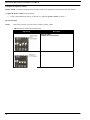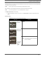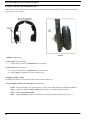
1
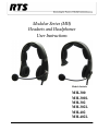
Modular Series (MH)
Headsets and Headphones
User Instructions
Models Include:
MH-300
MH-300L
MH-302
MH-302L
MH-402
MH-402L
F01U217863(LIT000404000) Rev 04
4/2011
PROPRIETARY NOTICE
The product information and design disclosed herein were originated by
and are the property of Bosch Security Systems, Inc. Bosch reserves all
patent, proprietary design, manufacturing, reproduction, use and sales
rights thereto, and to any article disclosed therein, except to the extent
rights are expressly granted to others.
COPYRIGHT NOTICE
Copyright 2011 by Bosch Security Systems, Inc. All rights reserved.
Reproduction, in whole or in part, without prior written permission from
Bosch is prohibited.
WARRANTY AND SERVICE INFORMATION
For warranty and service information, refer to the appropriate web site
below:
RTS ....................................................... www.rtsintercoms.com/warranty
RTSTW............................................................. www.rtstw.com/warranty
AudioCom .........................................www.telexaudiocom.com/warranty
RadioCom.......................................... www.telexradiocom.com/warranty
Headsets........................................ www.intercomheadsets.com/warranty
REGULATORY INFORMATION
FCC
This device complies with part 15 of the FCC Rules. Operation is
subject to the following two (2) conditions: (1) This device may not
cause harmful interference, and (2) this device must accept any
interference received, including interference that may cause
undesired operation.
CE
This product meets Electromagnetic Compatibility Directive 2004/108/EC
LIMIT LEVELING
The MH series headset and headphones are audio level limited and
conform to the EU Council Directive 2003/10/EC. The time/weighted
average of noise exposure levels for a nominal 8-hour working day is not
expected to exceed 85dB SPL and a peak of 137dB SPL.
Available MH Series Accessories
Ear Cushion ......................................................................................................................................................................................................F01U149725
Dynamic Microphone Windscreen ...................................................................................................................................................................F01U149727
Headband Pad ...................................................................................................................................................................................................F01U149729
Battery ..............................................................................................................................................................................................................F01U149731
Battery Charger North America........................................................................................................................................................................F01U149733
World Power Supply Adapters .........................................................................................................................................................................F01U149735
Aux Audio Input Module .................................................................................................................................................................................F01U149737
Single-Sided Passive Headset Frame Assembly ..............................................................................................................................................F01U149739
Double-Sided Passive Headset Frame Assembly .............................................................................................................................................F01U149741
Analog ANR Headset Frame Assembly ...........................................................................................................................................................F01U149743
Dynamic Microphone Module, Quick Disconnect Connector .........................................................................................................................F01U149745
Cable, Quick Disconnect to A4M Connector ...................................................................................................................................................F01U149747
Cable, Quick Disconnect to A4F Connector ....................................................................................................................................................F01U149749
Cable, Quick Disconnect to A5M Connector ...................................................................................................................................................F01U149751
Cable, Quick Disconnect to A5F Connector ....................................................................................................................................................F01U149753
Cable, Quick Disconnect to Pigtail...................................................................................................................................................................F01U149755
Filler Module ....................................................................................................................................................................................................F01U149757
Temple Pad .......................................................................................................................................................................................................F01U149759
Carrying Case ...................................................................................................................................................................................................F01U149761
Dynamic Microphone Module, A4M Connector .............................................................................................................................................F01U167564
Dynamic Microphone Module, A4F Connector...............................................................................................................................................F01U167565
Dynamic Microphone Module, A5M Connector .............................................................................................................................................F01U167566
Dynamic Microphone Module, A5F Connector...............................................................................................................................................F01U167567
Dynamic Microphone Module, Pigtail .............................................................................................................................................................F01U167568
Headpad, 3-piece ..............................................................................................................................................................................................F01U217632
Table
of
Contents
INTRODUCTION ................................................................................................................................... 3
Important Safety Instructions .............................................................................................................................. 3
General Description ............................................................................................................................................. 3
Features ................................................................................................................................................................ 4
MH-300/MH-300L (no ANR)
Single-Sided Headset/Headphone ....................................................................................................................... 5
MH-302/MH-302L (no ANR) & MH-402/MH-402L (ANR capable)
Dual-Sided Headset/Headphone .......................................................................................................................... 6
Battery Charger ................................................................................................................................................... 7
Battery Charger Power Supply ............................................................................................................................ 7
CONFIGURATION, OPERATION AND MAINTENANCE ............................................................... 9
Before First Use ................................................................................................................................................... 9
Battery Charging (MH-402 Series) ...................................................................................................................................9
Battery Installation (MH-402 Series) ................................................................................................................................9
Remove and Replace any Headset Module ......................................................................................................................9
Configuration ..................................................................................................................................................... 11
Access the Dip Switches .................................................................................................................................................11
Configure the Speaker Volume .......................................................................................................................................12
Dip Switch Settings .....................................................................................................................................................12
Configure Speaker Mode ................................................................................................................................................13
Dip Switch Settings .....................................................................................................................................................13
Configure ANR (MH-402 and MH-402L Only) ............................................................................................................14
Configure Auxiliary Audio .............................................................................................................................................14
Operation and Maintenance ............................................................................................................................... 15
Headset Adjustment and Sizing ......................................................................................................................................15
Microphone Adjustment .................................................................................................................................................15
Replace the Earcup, Temple and Headband Cushion .....................................................................................................15
Replace the Windscreen ..................................................................................................................................................19
Care and Maintenance ....................................................................................................................................... 19
Clean the Headset ...........................................................................................................................................................19
Store/Transport the Headset (MH-402 and MH-402L Only) .........................................................................................19
BATTERY MODULE ............................................................................................................................ 21
Battery Module .................................................................................................................................................. 21
Replace the Battery .........................................................................................................................................................21
Charge the Battery ..........................................................................................................................................................22
CONNECTORS ..................................................................................................................................... 25
XLR Connectors ................................................................................................................................................25
Pig Tail Connector .............................................................................................................................................26
Quick Disconnect ...............................................................................................................................................27
SPECIFICATIONS ............................................................................................................................... 29
Specifications .....................................................................................................................................................29
Speaker ............................................................................................................................................................................29
Noise Reduction ..............................................................................................................................................................29
Microphone .....................................................................................................................................................................29
General ............................................................................................................................................................................29
TROUBLESHOOTING AND FAQS .................................................................................................... 31
Where do I send my headset for repair? .........................................................................................................................31
My ANR (Automatic Noise Reduction) Headset is no longer working. ........................................................................31
My headset does not work with my MP3 player. ...........................................................................................................31
I need parts for my headset. ............................................................................................................................................32
How long will it take my headset to be repaired? ...........................................................................................................32
List
of
Figures
FIGURE 1.
FIGURE 2.
FIGURE 3.
FIGURE 4.
FIGURE 5.
FIGURE 6.
FIGURE 7.
FIGURE 8.
FIGURE 9.
FIGURE 10.
Models MH-300 and MH-300L ............................................................................................................5
Models MH-302, MH-302L, MH-402, and MH-402L .........................................................................6
Battery Charger Reference Diagram .....................................................................................................7
Standard Power Supply and Plug Adapters ..........................................................................................7
ANR Switch ........................................................................................................................................14
MH-402/402L in Carrying Case .........................................................................................................19
Battery Charger Reference Diagram ...................................................................................................22
4-Pin XLR Connector Female and Male ............................................................................................25
5-Pin XLR Connector Female and Male ............................................................................................26
Quick Disconnect Connector ..............................................................................................................27
CHAPTER 1
Introduction
Important Safety Instructions
1.
Read these instructions.
2.
Keep these instructions.
3.
Heed all warnings.
4.
Follow all instructions.
5.
This headset is capable of producing sound pressure levels in excess of 100dB SPL.
6.
Refer all servicing to qualified service personnel. Servicing is required when the headset is damaged in any way, such
as power-supply cord or plug is damaged, liquid has been spilled into the headset, the headset is exposed to rain or
moisture, or does not operate normally.
7.
The battery used with these headsets is a Lithium based unit. This unit must only be charged with the RTS specified
battery charger. Care should be used when storing the battery; ensuring the terminals are not shorted together.
General Description
The MH Series Headsets and Headphones provide the newest design in headset technology from RTS. With its rugged
modular design, lightweight construction, installation options, and its multi-function use beyond the live studio or theater
venue, the MH Series Headsets are designed with you, the user, in mind. The modular design allows you to interchange
different modules to customize the best headset for your environment. The noise-canceling microphone, combined with the
headphone transducers and ANR (Active Noise Reduction) provides clear and precise communication in noisy environments.
Finally, this headset is not limited to live studio or venue communication. By installing the auxiliary audio input module, you
can connect to an MP3 player, and many other audio devices.
The MH Series Headsets and Headphones provide clear communication for professional applications, including live remote or
studio broadcasting, film, TV, and theater intercom communications.
TERMINOLOGY:
In this manual, a Headset refers to a device you wear on your head that allows you to both listen
and speak. A headset always has a microphone. Headphones are an audio only device you wear
on you head that allows you to listen only.
3
Modular Series (MH) Headsets and Headphones User Manual
Features
Three (3) Headset The MH Series gives you three (3) options when selecting the type of headset for your environment:
• Single-Sided Headset without ANR (model MH-300 and MH-300L)
Frame Options • Dual-Sided Headset without ANR (model MH-302 and MH-302L
• Dual-Sided Headset with ANR (model MH-402 and MH-402L)
Cord Termination - The MH Series Headset and Headphone is available with multiple cord termination configurations; 4-pin
XLR male and female, 5-pin XLR male and female, pigtail, quick disconnect, and 3.5mm plug (with the
Auxiliary Audio Module). The quick disconnect option allows for quickly terminating your headset to
4- and 5-pin XLR connectors (male and female) and to a pigtail cord end to meet the needs of the headset
or headphone application.
4
Modular Design -
The modular design of the MH Series allows for many options when configuring the perfect headset for
use in your specific environment. All the modules are universal which means they are fully
interchangeable, and giving you more flexibility in your headset needs. The versatility of the
MH Dual-Sided Series is obvious when using the music/audio module. Installing the auxiliary audio
module turns the broadcast headset into an every day, every where headset, allowing for MP3 player
hookup, GPS connection, and many other applications.
Acoustic
Performance -
Expanded frequency response ensures clear communications and enhanced audio performance. The
adjustable output level allows the user to match the headset to the requirements of the surrounding
environment. Acoustic design and active noise reduction, available with the MH-402/402L, combine to
remove common environmental noises.
Comfortable
Design -
The design of the MH Series headset with its headband location in relation to the ear cups delivers more
stability when the headset is being worn. All user contact points, ear cup cushions, temple pads,
headband cushions, and the windscreen are completely replaceable allowing for good hygiene.
Introduction
MH-300/MH-300L (no ANR)
Single-Sided Headset/Headphone
FIGURE 11.
NOTE:
Models MH-300 and MH-300L
The MH-300L is a listen-only headphone. It does not have a microphone.
1.
Headset Frame
2.
Microphone Module or Auxiliary Audio Input Module
3.
Temple Pad
4.
Headband Pad
5.
Ear Cushion
6.
Windscreen
7.
Side Cushions
5
Modular Series (MH) Headsets and Headphones User Manual
MH-302/MH-302L (no ANR) & MH-402/MH-402L (ANR capable)
Dual-Sided Headset/Headphone
FIGURE 12.
NOTE:
Models MH-302, MH-302L, MH-402, and MH-402L
The MH-302L and the MH-402L are listen-only headphones. They do not have a microphone.
1.
Headset Frame
2.
Microphone Module or Auxiliary Audio Input Module
3.
Headband Pad
4.
Ear Cushion
5.
Filler Module or Battery Module
6.
Windscreen
7.
Side Cushions
8.
ANR Switch (MH-402/402L versions only)
NOTE: The switch label is used to determine the on and off position for ANR.
6
Introduction
Battery Charger
NOTE:
For more information, see “Battery Module” on page 21.
FIGURE 13.
Battery Charger Reference Diagram
1.
Operation LED
2.
Module Release Button
3.
Power Supply Connector
Battery Charger Power Supply
FIGURE 14.
Standard Power Supply and Plug Adapters
Standard Power Supplya
World Power Supply Adapters (Optional - P/N
PRD000260005)
1.
Wall Pack
3.
UK Plug (optional)
2.
US Plug (standard)
4.
Euro Plug (optional)
5.
Australian Plug (optional)
a.
The MH-402 and MH-402L come standard with the AC Adapter kit which includes all of the above options (P/N
EML000012001)
7
Modular Series (MH) Headsets and Headphones User Manual
8
CHAPTER 2
Configuration, Operation and
Maintenance
The MH Series Headsets and Headphones were designed for use in multiple applications. As such, when using the headsets
and headphones specific for you application, refer to the following sections to verify the proper configuration and settings.
Before First Use
Battery Charging (MH-402 Series)
For information on charging the battery, see “Charge the Battery” on page 22.
Battery Installation (MH-402 Series)
For information on installing the battery, see “Battery Module” on page 21.
Remove and Replace any Headset Module
To remove a module, do the following:
1.
Press the module release button located at the bottom of the ear cup.
The module pops up from the ear cup.
2.
Slide the module out and up taking care to clear the mounting tab from the mounting tab hole.
9
Modular Series (MH) Headsets and Headphones User Manual
To replace a module, do the following:
10
1.
Align the mounting tab with the mounting tab hole.
2.
Slide the module into place.
3.
Press the module down, snapping it into the ear cup.
Configuration, Operation and Maintenance
Configuration
NOTE:
The MH Series headset and headphones have been configured for use in the most common applications. We
recommend the configuration not be changed unless absolutely necessary.
The following information details configuration settings for:
•
•
•
•
Speaker Volume (see “Configure the Speaker Volume” on page 12)
Speaker Mode (see “Configure Speaker Mode” on page 13)
ANR Mode (see “Configure ANR (MH-402 and MH-402L Only)” on page 14)
Auxiliary Audio (see “Configure Auxiliary Audio” on page 14)
Access the Dip Switches
The speaker volume or the speaker mode of your headset is configured using a series of dip switches located on the side of the
microphone module or listen-only module.
To access the dip switches, do the following:
NOTE: Dip switches are located on the microphone module and the listen-only module. This feature is not available
on the audio input module.
1.
Remove the microphone module or listen-only module.
2.
Locate the dip switch bank on the side of either the microphone module or the listen-only module.
11
Modular Series (MH) Headsets and Headphones User Manual
Configure the Speaker Volume
Speaker Volume is configured using dip switch settings located on the microphone module and the listen-only module.
To adjust the speaker volume, do the following:
>
Using a small flathead screwdriver (or other device), adjust the speaker volume. See Table 1.
Dip Switch Settings
NOTE:
Only switch positions 3 and 4 are used to configure speaker volume.
TABLE 1. Speaker
Volume Dip Switch Settings
Dip Switch
Description
Reduced Volume
(-10dB from Normal Volume)
Normal Volume (Default)
12
Configuration, Operation and Maintenance
Configure Speaker Mode
Audio on the headset can be configured to be heard either Mono, Left Only, or Stereo. This means it can come from both sides
of the headset or from the left side only.
NOTE:
The stereo option can only be used with the 5-pin XLR connector versions.
This configuration is done through setting dip switches located on the main board of the headset.
NOTE:
To access the Dip Switches, see “Access the Dip Switches” on page 11.
To configure speaker mode, do the following:
>
Using a small flathead screwdriver (or other device), set the dip switches to the mode of operation desired. See
Table 2.
Dip Switch Settings
TABLE 2. Mono,
Stereo, or Left Only Dip Switch Settings
Dip Switch
Description
Mono Mode
(Default)
Left Only Mode
Stereo Mode
NOTE: Any module using A5M or A5F connectors
has stereo capabilities.
13
Modular Series (MH) Headsets and Headphones User Manual
Configure ANR (MH-402 and MH-402L Only)
ANR is used to reduce unwanted noise in the headset from the surrounding environment. The ANR switch is located on the
left ear cup, as seen in Figure 15.
FIGURE 15.
ANR Switch
To turn ANR on, do the following:
>
On the left ear cup, move the ANR switch to the up position.
To turn ANR off, do the following:
1.
On the left ear cup, move the ANR switch to the down position.
2.
Remove battery, if applicable, to conserve battery power.
Configure Auxiliary Audio
The MH Series headset can also be used to listen to music, GPS information, etc.
To use the MH Series headset for audio input, do the following:
NOTE: The battery module is only needed when you want to use the ANR feature of the MH-402 or MH 402L.
14
Step 1
If necessary, install the battery module into the headset. See “Battery Module” on page 21.
Step 2
Install the audio input module.
Step 3
Adjust the headset for proper fit and comfort. See “Headset Adjustment and Sizing” on page 15.
Configuration, Operation and Maintenance
Operation and Maintenance
To operate the MH Series headset, do the following:
Step 1
Adjust the headset for proper fit and comfort. See “Headset Adjustment and Sizing” on page 15.
Step 2
Adjust the microphone for proper use.
Step 3
Turn on ANR. See “Configure ANR (MH-402 and MH-402L Only)” on page 14.
Step 4
Plug the headset in.
Headset Adjustment and Sizing
The headset should fit comfortably over the head and ears without pinching or gapping. A comfortable fit is conducive to
effective and pleasant use.
To adjust the headband size, do the following:
1.
With the headset resting securely on the top of the head, slide the ear cup up and down to center the ear cup over the
ear.
2.
Swivel the ear cup left or right to position the ear cup flat on the ear.
Microphone Adjustment
From the factory, the microphone is installed on the left side of the headset. However, you can interchange the microphone for
right-side use, see “Remove and Replace any Headset Module” on page 9.
Replace the Earcup, Temple and Headband Cushion
There are three (3) cushion replacement points on the MH Series Headset; ear cups, temple pads, and the headband.
15
Modular Series (MH) Headsets and Headphones User Manual
The MH-302/302L and the MH-402/402L have two (2) ear cup cushions and a headband cushion, while the MH-300/300L has
one (1) ear cup cushion, one (1) temple pad, and a headband cushion.
To replace the ear cup cushion, do the following:
1.
Grasp the worn ear cushion and carefully pull it off the ear cup.
2.
Starting at the top of the ear cup, place the top part of the back flap of the new ear cushion over the top lip of the
ear cup.
NOTE: The ear cup cushion hole orients to the bottom of the ear cup.
16
3.
Using your fingers, work the back flap of the ear cushion around the ear cup.
4.
Pull the bottom of the ear cushion over the bottom lip of the ear cup.
Configuration, Operation and Maintenance
To replace the headband cushion, do the following:
1.
Grasp the headband cushion.
2.
Pull the worn cushion off the headband.
3.
Remove the protective paper from the sticky side of the new headband cushion.
NOTE: The headband is affixed to the headband with adhesive tape.
4.
Align the new headband cushion to the headband frame.
5.
Firmly press the new headband cushion in place.
To replace the three-cushion version headband cushion, do the following:
1.
Grasp the headband cushion.
2.
Pull the old cushion off the headband.
3.
Align the new top cushion to the top of the headband.
4.
Align the right side cushion to the right side of the headband.
5.
Align the left side cushion to the left side of the headband.
6.
Firmly press the new headband cushions in place.
17
Modular Series (MH) Headsets and Headphones User Manual
To replace the temple pad cushion, do the following:
1.
Grasp the temple pad cushion.
2.
Pull the worn cushion off.
3.
Remove the protective paper from the sticky side of the new temple pad cushion.
NOTE: The temple pad is affixed to the headband with adhesive tape.
18
4.
Align the new temple pad cushion to the headband frame.
5.
Firmly press the new temple pad cushion in place.
Configuration, Operation and Maintenance
Replace the Windscreen
To replace the wind screen, do the following:
1.
Remove the worn windscreen from the microphone and discard.
2.
Gently pull the new windscreen over the microphone.
Care and Maintenance
Clean the Headset
When cleaning your headset, do the following:
•
•
IMPORTANT:
use a soft, slightly damp cloth (water only).
if necessary, a mild mix of soapy water may be used.
Excessive water can damage the headset and cause short circuits to the electrical components of the
unit. Do not use solvents or chemicals when cleaning your headset as it may cause damage or
inoperability.
Store/Transport the Headset (MH-402 and MH-402L Only)
For storing or transporting your MH-402/402L headset, use the protective carrying case the headset is shipped in. Place the
headset in the carrying case as shown in Figure 16.
FIGURE 16.
MH-402/402L in Carrying Case
19
Modular Series (MH) Headsets and Headphones User Manual
20
CHAPTER 3
Battery Module
Battery Module
The battery module is only used with the MH-402 and MH-402L ANR headset/headphone. By using the battery and enabling
the ANR, the audio quality is markedly enhanced.
NOTE:
The battery charger uses a universal power pack with a mini-USB connector that is compatible with many
devices that accept the connector, for example a cell phone.
Replace the Battery
CAUTION: If this is the first time using the batteries, see “Charge the Battery” on page 22.
Batteries can be installed on either ear cup (the left or right).
To replace a battery module, do the following:
1.
Align the mounting tab with the mounting tab hole.
2.
Slide the battery module into place.
3.
Press down on the battery module, snapping it into the ear cup.
21
Modular Series (MH) Headsets and Headphones User Manual
Charge the Battery
IMPORTANT:
FIGURE 17.
Before installing the battery for the first time, charge the battery for at least an hour and a half to ensure
a fully charged unit. A fully charged battery lasts approximately 40 hours between charges.
Battery Charger Reference Diagram
The battery charger has an LED, shown in Figure 17, that displays two(2) color states:
Green LED – The charger is on.
Red LED – The battery is being charged. Once the battery is done charging, the green LED appears.
NOTE: If the battery is damaged and not able to charge or if the battery is fully charged, the red LED does not
display.
The power module for the battery charger comes with the US connection adaptor as standard. There are three (3) optional
connection adapters (Euro, UK, and Australian), also known as the world adapters.
22
Battery Module
To change the connection adapter for the power module, do the following:
1.
While pressing the adapter lock button, turn the adapter counter-clockwise to release the adapter.
2.
Replace the current adapter with the desired power module adapter.
3.
Turn the new adapter clockwise to lock it in place.
To charge a battery, do the following:
1.
Plug the power supply into an electrical outlet.
2.
Attach the power supply to the charger.
The LED lights green.
23
Modular Series (MH) Headsets and Headphones User Manual
24
3.
Align the mounting tab with the mounting tab hole on the battery charger.
4.
Slide the battery module into place.
5.
Press down on the battery module, snapping it into the ear cup.
The LED lights red while the battery is charging, and lights green when it is finished charging.
CHAPTER 4
Connectors
XLR Connectors
FIGURE 18.
4-Pin XLR Connector Female and Male
TABLE 3. 4-Pin
XLR Pin Out
Pin
Wire Color
Description
1
Blue
MIC -
2
White
MIC +
3
Black/Outer Shield
SPK -
4
Yellow/Red
R SPK and L SPK (dual)
Case
Inner Shield
MIC SHIELD
25
Modular Series (MH) Headsets and Headphones User Manual
FIGURE 19.
5-Pin XLR Connector Female and Male
TABLE 4. 5-Pin
Pin
XLR Pin Out
Wire Color
Description
1
Blue
MIC -
2
White
MIC +
3
Black/Outer Shield
SPK -
4
Yellow
L SPK +
5
Red
N/C (single) R SPK + (dual)
Case
Inner Shield
MIC SHIELD
Pig Tail Connector
Pigtail connectors give you maximum flexibility in the type of connector you want to use. Table 5shows the wire colors and
descriptions for the pigtail.
TABLE 5. Pig
Tail Connector Pin Out
Description
26
Color
Speaker Left +
Yellow
Speaker Right +
Red
Speaker -
Black/Outer Shield
Mic +
White
Mic -
Blue/Inner Shield
Power +
Green
Power -
Black/Outer Shield
Connectors
Quick Disconnect
The Quick Disconnect allows you to quickly switch connector types without having to switch headsets, saving time and space
when you are on the go.
FIGURE 20.
Quick Disconnect Connector
To disconnect the quick disconnect connector, do the following:
1.
Holding the quick disconnect in both hands, gently push each connector end toward each other (see Figure 20, A).
2.
While pushing toward each connector end, twist the connector ends in opposite directions so they unlock.
The connector comes apart (see Figure 20, B).
To connect the quick disconnect connector, do the following:
1.
Align the opposite connector ends.
2.
Gently push each connector end toward each other.
3.
While pushing toward each connector end, twist the connector ends in opposite directions so they lock.
TABLE 6. Quick
Disconnect Pin Assignments
Pin
Color
Description
1
Yellow
Speaker Left +
2
Red
Speaker Right +
3
Black
Speaker -
4
White
Mic +
5
Blue/Inner Shield
Mic -
6
Green
Power +
7
Outer Shield
Power -
8
N/C
N/C
27
Modular Series (MH) Headsets and Headphones User Manual
28
CHAPTER 5
Specifications
Specifications
Speaker
Transducer Type ............................................................................................................................................................... Dynamic
Sensitivity........................................................................................................ 100dB SPL/mW at 1kHz (normal volume setting)
Impedance ................................................................................................................................................................150Ω nominal
Frequency Response..............................................................................................................................................100Hz to 10kHz
Distortion............................................................................................................................................................................... <10%
Noise Reduction
ANR Models MH-402 and MH-402L Only.......................................... up to 12dB noise reduction between 100Hz and 2000Hz
Microphone
Type.........................................................................................................................................................Noise canceling dynamic
Impedance .............................................................................................................................................................................. 200Ω
Sensitivity................................................................................................................................................................200Hz to 5kHz
Distortion................................................................................................................................................................................. <5%
General
Gross Weight ....................................................................... MH-300, 8oz (226g); MH-302, 10oz (284g); MH-402, 10oz (284g)
Cord Length ................................................................................................................................................................5.9ft. (1.8m)
Color.......................................................................................................................................................................................Black
29
Modular Series (MH) Headsets and Headphones User Manual
30
CHAPTER 6
Troubleshooting and FAQs
PROBLEM
Where do I send my headset for repair?
SOLUTION
Attn: Customer Service
Bosch Communications, Inc.
8601 East Cornhusker Hwy.
Lincoln, NE 68507 U.S.A
Please include a copy of receipt, if available. Along with the
unit, please include your name, billing, and shipping
address, telephone number, and a brief description of the
problem you are experiencing.
Allow 7-10 working days for service, plus transportation
time, once we have received the unit for repair/refurbish.
For questions about repair, please call customer service at:
800-553-5992
My ANR (Automatic Noise Reduction) Headset is
no longer working.
My headset does not work with my MP3 player.
•
Verify the ANR switch is in the on
position.
•
Verify the battery is installed
properly.
•
•
Verify the battery is charged.
•
Verify the headset is on the head
properly.
•
Verify the ear cushions are seated on
the ear properly.
•
If you have verified the previous
bullets, then send the unit in for
repair.
•
Verify the cord for the device is
plugged in firmly.
Verify the cushions are installed
properly.
31
PROBLEM
I need parts for my headset.
How long will it take my headset to be repaired?
SOLUTION
•
Contact customer service for the part
number you are looking for.
Repair duration is usually 7 to 10 working days plus
shipping time back to the customer.