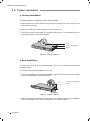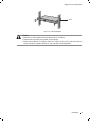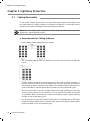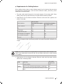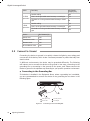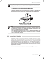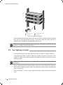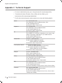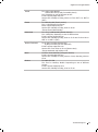
1
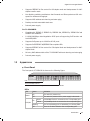
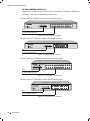
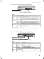
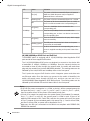
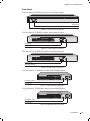
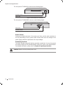
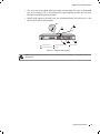
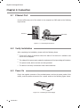
Enterprise Networking Solution
Installation Guide
Gigabit Unmanaged Switch
TL-SG1048
TL-SG1024/TL-SG1024D
TL-SG1016/TL-SG1016D
TL-SG1008/TL-SG1008PE
COPYRIGHT & TRADEMARKS
Specifications are subject to change without notice.
is a registered trademark
of TP-LINK TECHNOLOGIES CO., LTD. Other brands and product names are trademarks of their
respective holders.
No part of the specifications may be reproduced in any form or by any means or used to make
any derivative such as translation, transformation, or adaptation without permission from TP-LINK
TECHNOLOGIES CO., LTD. Copyright © 2013 TP-LINK TECHNOLOGIES CO., LTD. All rights reserved.
http://www.tp-link.com
FCC STATEMENT
This equipment has been tested and found to comply with the limits for a Class A digital device,
pursuant to part 15 of the FCC Rules. These limits are designed to provide reasonable protection
against harmful interference when the equipment is operated in a commercial environment. This
equipment generates, uses, and can radiate radio frequency energy and, if not installed and used in
accordance with the instruction manual, may cause harmful interference to radio communications.
Operation of this equipment in a residential area is likely to cause harmful interference in which case
the user will be required to correct the interference at his own expense.
This device complies with part 15 of the FCC Rules. Operation is subject to the following two
conditions:
111
This device may not cause harmful interference.
222
This device must accept any interference received, including interference that may cause
undesired operation.
Any changes or modifications not expressly approved by the party responsible for compliance could
void the user’s authority to operate the equipment.
CE Mark Warning
This is a Class A product. In a domestic environment, this product may cause radio interference, in
which case the user may be required to take adequate measures.
Copyright & Trademarks
I
Related Document
This Installation Guide is also available in PDF on our website. To obtain the latest
documentation and product information, please visit the official website:
http://www.tp-link.com
About this Installation Guide
This Installation Guide describes the hardware characteristics, installation methods
and the points that should be attended to during the installation. This Installation
Guide is structured as follows:
Chapter 1 Introduction. This chapter describes the external components of
the switch.
Chapter 2 Installation. This chapter illustrates how to install the switch.
Chapter 3 Lightning Protection. This chapter illustrates how to prevent lightning damage.
Chapter 4 Connection. This chapter illustrates how to do the physical connection of the switch.
Appendix A Troubleshooting.
Appendix B Specifications.
Appendix C Technical Support.
Audience
This Installation Guide is for:
Network Engineer
Network Administrator
Conventions
Due to the similarity in structure of the Gigabit Unmanaged Switch series, in
this Installation Guide we take TL-SG1024 as an example to illustrate Chapter 2
Installation, Chapter 3 Lightning Protection and Chapter 4 Connection.
This Guide uses the specific formats to highlight special messages. The following
table lists the notice icons that are used throughout this guide.
Remind to be careful. A caution indicates a potential which may result in
device damage.
Remind to take notice. The note contains the helpful information for a
better use of the product.
II
Related Document
Contents
Chapter 1
Introduction ——————————— 01
1.1
Product Overview ...................................................................01
1.2
Features ......................................................................................01
1.3
Appearance ...............................................................................02
Chapter 2
Installation ———————————— 08
2.1
Package Contents ...................................................................08
2.2
Safety Precautions ..................................................................08
2.3
Installation Tools......................................................................10
2.4
Product Installation ................................................................11
Chapter 3
Lightning Protection ———————— 13
3.1
Cabling Reasonably................................................................13
3.2
Connect to Ground.................................................................15
3.3
Equipotential Bonding ..........................................................16
3.4
Use Lightning Arrester ..........................................................17
Chapter 4
Connection ——————————— 19
4.1
Ethernet Port ............................................................................19
4.2
Verify Installation ....................................................................19
4.3
Power On....................................................................................19
4.4
Initialization ..............................................................................20
Appendix A Troubleshooting ————————— 21
Appendix B Specifications——————————— 22
Appendix C Technical Support ————————— 23
Contents
III
Gigabit Unmanaged Switch
CCCCCCCCCC Introduction
1111
Product Overview
The Gigabit Unmanaged Switch provides you with a high-performance, low-cost, easyto-use, seamless and standard upgrade to boost your old network to 1000Mbps.
By increasing the speed of your network server and backbone connections, the
Gigabit Unmanaged Switch makes Gigabit a reality. Power users in the home, office,
workgroup, or creative production environment can now move large, bandwidthintensive files faster. Graphics, CGI, CAD, multimedia files and other large files moved
by some applications can be transferred across the network almost instantly.
The Gigabit Unmanaged Switch features a non-blocking switching architecture that
forwards and filters packets at full wire-speed for maximum throughput. The switch
supports MAC address auto-learning and auto-aging, IEEE802.3x flow control for fullduplex mode and backpressure for half-duplex mode. It is compatible with all 10Mbps,
100Mbps and 1000Mbps Ethernet devices because it is standard-based. It protects
your existing network investments while providing you with a straightforward migration
path to faster Gigabit speed.
The Gigabit Unmanaged Switch is plug-and-play and no configuration is required.
Auto MDI/MDI-X cable detection on all ports eliminates the need for crossover cable
or Uplink port. Each port can be used as general port or Uplink port, and any port can
be simply plugged into a server, a hub, a router or a switch, using the straight cable
or crossover cable. Diagnostic LEDs which display link status and activity, allow you to
quickly detect and correct problems on the network.
TL-SG1008PE is a Power Sourcing Equipment (PSE*). The 8 Auto-Negotiation RJ45
ports support Power over Ethernet (PoE*) function, which can automatically detect and
supply power with those IEEE802.3af/IEEE802.3at-compliant powered devices (PDs*).
Note:
*PSE is a device (switch or hub for instance) that will provide power in a PoE setup.
*PoE is a technology that describes a system to transmit electrical power, along with
data, to remote devices over standard twisted-pair cable in an Ethernet network.
*PD is a device powered by a PSE and thus consumes energy. Examples include
powering IP telephones, wireless LAN access points, network cameras, network hubs,
embedded computers, etc.
■■
■■
■■
1111 Features
For TL-SG1048/TL-SG1024/TL-SG1024D/TL-SG1016/TL-SG1016D/TL-SG1008:
01
Introduction
••
Complies with IEEE802.3, IEEE802.3u, IEEE802.3ab standards
••
8/16/24/48 10/100/1000Mbps Auto-Sense RJ45 ports supporting Auto-MDI/MDIX
••
All ports Support Full/Half Duplex transfer mode for 10/100Mbps and Full Duplex
transfer mode for 1000Mbps
Gigabit Unmanaged Switch
••
Supports IEEE802.3x flow control for full-duplex mode and backpressure for halfduplex transfer mode
••
Non-blocking switching architecture that forwards and filters packets at full wirespeed for maximum throughput
••
Supports MAC address auto-learning and auto-aging
••
Desktop and rack-mountable steel case
••
Internal power supply
For TL-SG1008PE:
••
Complies with IEEE802.3, IEEE802.3u, IEEE802.3ab, IEEE802.3x, IEEE802.3af and
IEEE802.3at standards
••
8 10/100/1000Mbps Auto-Negotiation RJ45 ports all supporting PoE function and
Auto-MDI/MDIX
••
Supports PoE power up to 124W for all PoE ports
••
Supports PoE IEEE802.3af/IEEE802.3at-compliant PDs
••
Supports IEEE802.3x flow control for Full-duplex Mode and backpressure for Halfduplex Mode
••
8K entry MAC address table of the TL-SG1008PE with auto-learning and auto-aging
••
Internal power supply
1111 Appearance
■■
Front Panel
The front panel of TL-SG1048 is shown as the following figure.
1
2
3
4
5
6
7
8
9
10
11
12
13
14
15
16
17
18
19
20
21
22
23
24
25
26
27
28
29
30
31
32
33
34
35
36
37
38
39
40
41
42
43
44
45
46
47
48
1000Mbps
10/100Mbps
activity
Power
TL-SG1048
48-Port Gigabit Switch
LEDs
10/100/1000Mbps RJ45 Port
FFFFFFFFFFF Front Panel of TL-SG1048
LEDs
LED
Power
Status
Indication
On
The switch is powered on.
Off
On
Link/Act
The switch is powered off or power supply is abnormal.
Green
A 1000Mbps device is connected to the corresponding port.
Yellow
A 10/100Mbps device is connected to the corresponding port.
Flashing
The corresponding port is transmitting or receiving data.
Off
There is no device linked to the corresponding port.
Introduction
02
Gigabit Unmanaged Switch
10/100/1000Mbps RJ45 Port
Designed to connect to the device with a bandwidth of 10Mbps, 100Mbps or
1000Mbps. Each has a corresponding Link/Act LED.
The front panel of TL-SG1024 is shown as the following figure.
LEDs
10/100/1000Mbps RJ45 Port
FFFFFFFFFFF Front Panel of TL-SG1024
The front panel of TL-SG1016 is shown as the following figure.
LEDs
10/100/1000Mbps RJ45 Port
FFFFFFFFFFF Front Panel of TL-SG1016
The front panel of TL-SG1024D is shown as the following figure.
LEDs
10/100/1000Mbps RJ45 Port
FFFFFFFFFFF Front Panel of TL-SG1024D
The front panel of TL-SG1016D is shown as the following figure.
LEDs
10/100/1000Mbps RJ45 Port
FFFFFFFFFFF Front Panel of TL-SG1016D
03
Introduction
Gigabit Unmanaged Switch
The front panel of TL-SG1008 is shown as the following figure.
TL-SG1008
Link
Act
8-Port Gigabit Switch
Power
1
2
3
4
5
6
7
1
2
3
4
5
6
7
8
8
1000Mbps
LEDs
10/100/1000Mbps RJ45 Port
FFFFFFFFFFF Front Panel of TL-SG1008
LEDs
LED
Power
Link/Act
1000Mbps
Status
Indication
On
The switch is powered on.
Off
The switch is powered off or power supply is abnormal.
On
There is a device linked to the corresponding port but no
activity.
Flashing
The corresponding port is transmitting or receiving data.
Off
There is no device linked to the corresponding port.
On
A 1000Mbps device is connected to the corresponding port.
Off
A 10/100Mbps device or no device is connected to the
corresponding port.
10/100/1000Mbps RJ45 Port
Designed to connect to the device with a bandwidth of 10Mbps, 100Mbps or
1000Mbps. Each has a corresponding Link/Act LED and a 1000Mbps LED.
The front panel of TL-SG1008PE is shown as the following figure.
LEDs
10/100/1000Mbps RJ45 Port and PoE Port
FFFFFFFFFFF Front Panel of TL-SG1008PE
LEDs
LED
Power
Link/Act
Status
Indication
On (green1
The switch is powered on.
Flashing (green1
Power supply is abnormal.
Off
The switch is powered off.
On (green1
A valid link is established on the port.
Flashing (green1
The corresponding port is transmitting or receiving
data.
Off
There is no device linked to the corresponding port.
Introduction
04
Gigabit Unmanaged Switch
LED
PoE MAX
Status
Indication
On (red1
The power of all the connected PoE ports is between
118W and 124W. No power may be supplied if
additional PDs are connected.
Flashing (red1
The power of all the connected PoE ports is >=124W.
Off
The power of all the connected PoE ports is <118W, or
there is no PD connected to the corresponding port.
On (green1
There is a 1000Mbps device connected to the
corresponding port.
Off
There is a 10/100Mbps device connected to the
corresponding port, or there is no device connected to
the corresponding port.
On (green1
There is a PoE PD connected to the port, which supply
power successfully.
Flashing (green1
The PoE power circuit may be in short or the power
current may be overloaded.
Off
No PD is connected to the corresponding port, or no
power is supplied according to the power limits of the
port.
1000Mbps
PoE Status
10/100/1000Mbps RJ45 Port and PoE Port
TL-SG1008PE switch is equipped with 8 10/100/1000Mbps Auto-Negotiation RJ45
ports and all of them support PoE function.
The 8 10/100/1000Mbps RJ45 ports are designed to connect to the device with
a bandwidth of 10Mbps, 100Mbps or 1000Mbps. Once the network devices are
connected to these 8 ports through the network cable, the switch will make them
plug and play according to the Auto-MDI/MDIX detection. The working status can be
indicated by the Link/Act LEDs and 1000Mbps LEDs on the front panel.
The 8 ports also support PoE function which integrates power and data onto
one Ethernet cable. Once the device you connect to the switch is identified, the
switch will supply power through the PoE port, and then you can use it as a
10/100/1000Mbps Auto-Negotiation RJ45 Ethernet port. The working status can be
indicated by the PoE MAX LED and PoE Status LEDs on the front panel.
Note:
If all PoE PDs power consumption is >=124W, a priority* will be arranged among the
PoE ports like port 1 > port 2 > port 3 > port 4 > port 5 > port 6 > port 7 > port 8,
then the system will cut off the power of the lowest-priority port.
*Priority is to protect the system when the system power is overloaded. For example,
Port 1, 2, 4 and 7 is using 30; the system power is 120W in total. If there is an
additional PD inserted to Port 3 with 25W, and then the system will cut off the power
of Port 7 because of the overloaded power, this means Port 1, 2 and 4 will use 30W,
and Port 3 will use 25W, no power will be supplied to Port 7.
Make sure the PDs you connected to the switch are compliant with IEEE802.3af/
IEEE802.3at standard.
■■
■■
■■
05
Introduction
Gigabit Unmanaged Switch
Rear Panel
The rear panel of TL-SG1048 is shown as the following figure.
Power Socket
Grounding Terminal
FFFFFFFFFFF Rear Panel of TL-SG1048
The rear panel of TL-SG1024 is shown as the following figure.
Power Socket
Grounding Terminal
FFFFFFFFFFF Rear Panel of TL-SG1024
The rear panel of TL-SG1016 is shown as the following figure.
Power Socket
Grounding Terminal
FFFFFFFFFFFF Rear Panel of TL-SG1016
The rear panel of TL-SG1024D is shown as the following figure.
Grounding Terminal
Power Socket
FFFFFFFFFFFF Rear Panel of TL-SG1024D
The rear panel of TL-SG1016D is shown as the following figure.
Grounding Terminal
Power Socket
FFFFFFFFFFFF Rear Panel of TL-SG1016D
Introduction
06
Gigabit Unmanaged Switch
The rear panel of TL-SG1008 is shown as the following figure.
Grounding Terminal
Power Socket
FFFFFFFFFFFF Rear Panel of TL-SG1008
The rear panel of TL-SG1008PE is shown as the following figure.
Power Socket
Grounding Terminal
FFFFFFFFFFFF Rear Panel of TL-SG1008PE
Power Socket
Connect the female connector of the power cord here, and the male connector to
the AC (Alternating Current) power outlet. Please make sure the voltage of the
power supply meets the requirement of the input voltage.
Grounding Terminal
The switch already comes with lightning protection mechanism. You can also ground
the switch through the PE (Protecting Earth) cable of AC cord or with Ground Cable.
For detailed information, please refer to Chapter 3 Lightning Protection.
Caution: Please use the provided power cord.
07
Introduction
Gigabit Unmanaged Switch
CCCCCCCCCC Installation
2222 Package Contents
Make sure that the package contains the following items. If any of the listed items is
damaged or missing, please contact your distributor.
One Switch
One Power Cord
This Installation Guide
Two mounting brackets and the
fittings
2222 Safety Precautions
To avoid any device damage and bodily injury caused by improper use, please observe
the following rules.
■■
Safety Precautions
■■
Keep the power off during the installation.
■■
■■
■■
Wear an ESD-preventive wrist strap, and make sure that the wrist strap has a good
skin contact and is well grounded.
Use only the power cord provided with the switch.
Make sure that the supply voltage matches the specifications indicated on the rear
panel of the switch.
■■
Ensure the vent hole is well ventilated and unblocked.
■■
Do not open or remove the cover of the switch.
■■
Before cleaning the device, cut off the power supply. Do not clean it by the waterish
cloth, and never use any other liquid cleaning method.
Installation
08
Gigabit Unmanaged Switch
■■
Site Requirements
Temperature/Humidity
40℃
0℃
Please keep a proper temperature and humidity in the equipment room. Too high/low
humidity may lead to bad insulation, electricity leakage, mechanical property changes
and corrosions. Too high temperature may accelerate aging of the insulation materials
and can thus significantly shorten the service life of the device. For normal temperature
and humidity of the device, please check the following table.
Environment
Temperature
Humidity
Operating
0℃ ~ 40℃
10% ~ F0%RH Non-condensing
Storage
-40℃ ~ F0℃
5% ~ F0%RH Non-condensing
Clearness
The dust accumulated on the switch can be absorbed by static electricity and result
in poor contact of metal contact points. Some measures have been taken for the
device to prevent static electricity, but too strong static electricity can cause deadly
damage to the electronic elements on the internal circuit board. To avoid the effect of
static electricity on the operation of the switch, please attach much importance to the
following items:
■■
Dust the device regularly, and keep the indoor air clean.
■■
Keep the device well grounded and ensure static electricity has been transferred.
Electromagnetic Interference
Electronic elements including capacitance and inductance on the device can be affected
by external interferences, such as conducted emission by capacitance coupling,
inductance coupling, and impedance coupling. To decrease the interferences, please
make sure to take the following measures:
■■
■■
■■
09
Installation
Use the power supply that can effectively filter interference from the power grid.
Keep the device far from high-frequency, strong-current devices, such as radio
transmitting station.
Use electromagnetic shielding when necessary.
Gigabit Unmanaged Switch
Lightening Protection
Extremely high voltage currents can be produced instantly when lightning occurs and the air
in the electric discharge path can be instantly heated up to 20,000℃. As this instant current
is strong enough to damage electronic devices, more effective lightning protection measures
should be taken.
■■
Ensure the rack and device are well earthed.
■■
Make sure the power socket has a good contact with the ground.
■■
Keep a reasonable cabling system and avoid induced lightning.
■■
Use the signal SPD (Surge Protective Device) when wiring outdoor.
Note: For detailed lightning protection measures, please refer to Chapter 3
Lightning Protection.
Installation Site
1.5m
When installing the device on a rack or a flat workbench, please note the following
items:
■■
■■
■■
The rack or workbench is flat and stable, and sturdy enough to support the weight
of 5.5kg at least.
The rack or workbench has a good ventilation system. The equipment room is well
ventilated.
The rack is well grounded. Keep the power socket less than 1.5 meters away from
the device.
2222 Installation Tools
■■
Phillips screwdriver
■■
ESD-preventive wrist wrap
■■
Cables
Note: These tools are not provided with our product. If needed, please self purchase
them.
Installation
10
Gigabit Unmanaged Switch
2222 Product Installation
■■
Desktop Installation
To install the device on the desktop, please follow the steps:
111Set the device on a flat surface strong enough to support the entire weight of the
device with all fittings.
222Remove the adhesive backing papers from the rubber feet.
333Turnover the device and attach the supplied rubber feet to the recessed areas on
the bottom at each corner of the device.
Feet
Bottom of the Device
Notch
FFFFFFFFFFF Desktop Installation
■■
Rack Installation
To install the device in an EIA standard-sized, 19-inch rack, follow the instructions
described below:
111Check the grounding and stability of the rack.
222Secure the supplied rack-mounting brackets to each side of the device with supplied
screws, as illustrated in the following figure.
Rack-mounting Bracket
Screw
FFFFFFFFFFF Bracket Installation
333After the brackets are attached to the device, use suitable screws (not provided) to
secure the brackets to the rack, as illustrated in the following figure.
11
Installation
Gigabit Unmanaged Switch
Rack
FFFFFFFFFFF Rack Installation
Caution:
Please set 5~10cm gaps around the device for air circulation.
Please avoid any heavy thing placed on the device.
Please mount devices in sequence from the bottom to top of the rack and ensure a
certain clearance between devices for the purpose of heat dissipation.
■■
■■
■■
Installation
12
Gigabit Unmanaged Switch
CCCCCCCCCC Lightning Protection
3333 Cabling Reasonably
In the actual network environment, you may need cable outdoors and indoors, and
the requirements for cabling outdoors and indoors are different. A reasonable cabling
system can decrease the damage of induced lightning to devices.
Note: It's not recommended using Ethernet cables outdoors. When cabling outdoors,
please use a signal lightning arrester.
■■
Requirements for Cabling Outdoors
■■
Aerial cabling without safeguard is not allowed.
■■
■■
■■
■■
13
It’s not allowed cabling down the building to connect network devices in different
floors.
Outdoor cables should be buried and paved to the indoor through basement. A
piece of steel wire should be paved underground along the pipe and connected to
the lightning protection terminal of the building for shielding. Before connecting the
cable to the device, install a signal lightning arrester on the corresponding port.
When an aerial cable is set up, the cable should be through a metal pipe (15m long
at least) before coming into the building. The two ends of this metal pipe should
be grounded. Before connecting the cable to the device, install a signal lightning
arrester on the corresponding port.
It’s not necessary to pave STP cables through pipes. The shielded layer of STP cable
should be well grounded. Before connecting the cable to the device, install a signal
lightning arrester on the corresponding port.
Lightning Protection
Gigabit Unmanaged Switch
■■
Requirements for Cabling Indoors
When cabling indoors, keep a certain distance away from the devices that may cause
high-frequency interferences, such as down-conductor cable, powerline, power
transformer and electromotor.
■■
■■
The main cable should be paved in the metal raceway of the access shaft. When
cabling, keep the loop area formed by the cable itself as small as possible.
Requirements for the distance between Ethernet cable and other pipelines are
shown in the table.
Ethernet Cable
Other Pipelines
Min Parallel Net Length L
(mm1
Min Parallel-overlapping
Net Height H (mm1
Down-conductor
1000
300
PE
50
20
Service pipe
150
20
Compressed air pipe
150
20
Thermal pipe (not wrapped1
500
500
Thermal pipe (wrapped1
300
300
Gas pipe
300
20
The two diagrams below demonstrate parallel net length and parallel-overlapping net
height.
Note: The above minimum net length/height is required when metal raceway is not
used. If any requirements cannot be met, you can add a steel tube or metal raceway
for shielding.
■■
Requirements for the distance between Ethernet cable and high-power electric
devices are in following tables.
Cable
<2kVA
powerline
Pave Way
Min Parallel
Length (mm1
Parallel cabling
130
One is in the grounded metal raceway or metal pipe
F0
The both are in the grounded metal raceway or metal
pipe
10
Lightning Protection
14
Gigabit Unmanaged Switch
Cable
2~5kVA
powerline
>5kVA
powerline
Pave Way
Min Parallel
Length (mm1
Parallel cabling
300
One is in the grounded metal raceway or metal pipe
150
The both are in the grounded metal raceway or metal
pipe
80
Parallel cabling
600
One is in the grounded metal raceway or metal pipe
300
The both are in the grounded metal raceway or metal
pipe
150
Device
Min Distance (m1
Switch case
1.00
Transformer room
2.00
Elevator tower
2.00
Air-conditioner room
2.00
3333 Connect to Ground
Connecting the device to ground is to quickly release the lightning over-voltage and
over-current of the device, which is also a necessary measure to protect the body from
electric shock.
In different environments, the device may be grounded differently. The following
will instruct you to connect the device to the ground in two ways, connecting to the
grounding bar or connecting to the ground via the power cord. Please connect the
device to ground in the optimum way according to your specific operation environment.
■■
Connecting to the Grounding Bar
If the device is installed in the Equipment Room, where a grounding bar is available,
you are recommended to connect the device to the grounding bar as shown in the
following figure.
Switch (Rear Panel)
Grounding Terminal
Ground Cable
Grounding Bar
FFFFFFFFFFF Connecting to the Grounding Bar
15
Lightning Protection
Gigabit Unmanaged Switch
Note: The grounding bar and the ground cable are not provided with our product. If
needed, please self purchase them.
■■
Connecting to the Ground via the Power Supply
If the device is installed in the normal environment, the device can be grounded via the
PE (Protecting Earth) cable of the AC power supply as shown in the following figure.
FFFFFFFFFFF Connecting to the Ground
Note:
The figure is to illustrate the application and principle. The power plug you get from
the package and the socket in your situation will comply with the regulation in your
country, so they may differ from the figure above.
If you intend to connect the device to the ground via the PE (Protecting Earth) cable
of AC power cord, please make sure the PE (Protecting Earth) cable in the electrical
outlet is well grounded in advance.
■■
■■
3333 Equipotential Bonding
Equipotential Bonding is the practice of intentionally electrically connecting all earthed
systems to the same grounding grid or connecting the grounding grids of all the
earthed systems together through the ground or overground metal so as to create
an earthed equipotential zone. When lightning occurs, the high voltage produced by
lightning current in all systems will meanwhile exist in their ground cables, and thus
all ground cables have the same electrical potential and basically eliminate the electric
strikes between the systems.
The figure below illustrates how to practice equipotential bonding in a network.
Lightning Protection
16
Gigabit Unmanaged Switch
Grounding Terminal
Equipotential Bonding Cable
Ground Cable
Grounding Bar
FFFFFFFFFFF Equipotential Bonding
When equipotential bonding, please note that the cable should be copper wrapped
2
Kelly with its area being 6mm at least. The shorter cable the better, and use a
grounding bar to establish an equipotential bonding point.
Note: The equipotential bonding cable and ground cable are not provided with our
product. If needed, please self purchase it.
3333 Use Lightning Arrester
Power lightning arrester and signal lightning arrester are used for lighting protection.
Power lightning arrester is used for limiting the voltage surge due to a lightning. If an
outdoor AC power cord should be directly connected to the device, please use a power
lightning arrester.
Note: Power lightning arrester is not provided with our product. If needed, please self
purchase it.
Signal lightning arrester is used to protect RJ45 ports of the device from lightning.
When cabling outdoors, please install a signal lightning arrester before connecting the
cable to the device.
When purchasing or using a signal lightning arrester, please observe the following
rules:
17
Lightning Protection
Gigabit Unmanaged Switch
■■
■■
The port rate of the signal lightning arrester should match the rate of the desired
port on the device. If it is not matched, this signal lighting arrester will not work.
Purchase a standard lightning arrester.
Install signal lightning arrester near the protected device and connect it to the
ground via a shorter ground cable.
Grounding Terminal
Equipotential Bonding Cable
Signal Lightning Arrester
Device
Ethernet Cable
FFFFFFFFFFF Equipotential Bonding
Note: Signal lightning arrester is not provided with our product. If needed, please self
purchase it.
Lightning Protection
18
Gigabit Unmanaged Switch
CCCCCCCCCC Connection
4444 Ethernet Port
Connect a Ethernet port of the switch to the computer by RJ45 cable as the following
figure shown.
RJ45 Port
RJ45 Cable
FFFFFFFFFFF Connecting the RJ45 Port
4444 Verify Installation
After completing the installation, please verify the following items:
■■
There are 5~10cm of clearance around the sides of the device for ventilation and
the air flow is adequate.
■■
The voltage of the power supply meets the requirement of the input voltage of the device.
■■
The power socket, device and rack are well grounded.
■■
The device is correctly connected to other network devices.
4444 Power On
Plug in the negative connector of the provided power cord into the power socket of the
device, and the positive connector into a power outlet as the following figure shown.
FFFFFFFFFFF Connecting to Power Supply
19
Connection
Gigabit Unmanaged Switch
Note: The figure is to illustrate the application and principle. The power plug you get
from the package and the socket in your situation will comply with the regulation in
your country, so they may differ from the figure above.
4444 Initialization
For TL-SG1048/TL-SG1024/TL-SG1024D/TL-SG1016/TL-SG1016D/TL-SG1008:
After the device is powered on, it begins the Power-On Self-Test. A series of tests run
automatically to ensure the device functions properly. During this time, its LED indicators will respond as follows:
■■
■■
All of the LED indicators will flash momentarily for one second, which represents a
resetting of the system.
The Power LED indicator will light up.
For TL-SG1008PE:
The LED indicators for TL-SG1008PE are classified into two parts:
The LEDs indicating switch status including Power LED, Link/Act LEDs and 1000Mbps
LEDs; the LEDs indicating PSE status, including PoE MAX LED and PoE Status LEDs.
After the device is powered on, it begins the Power-On Self-Test. A series of tests run
automatically to ensure the device functions properly. During this time, its LED indicators will respond as follows:
■■
■■
All of the LEDs indicating swith status will flash momentarily for one second, which
represents a resetting of the switch system. The PoE MAX LED will keep on for
approximately ten seconds, representing a resetting of the PSE system. Take note
that the PoE Status LEDs won't light up during this period.
The Power LED indicator will light up.
Connection
20
Gigabit Unmanaged Switch
Appendix A Troubleshooting
QQQQ The Power LED is not lit
The Power LED should be lit up when the power system works normally. If the
Power LED worked abnormally, please check as follows:
111 Make sure that the power cable is connected properly, and the power
contact is normal.
222 Make sure the voltage of the power supply meets the requirement of the
input voltage of the switch.
QQQQ The Link/Act LED is not lit when a device is connected to the
corresponding port
Please check as follows:
111 Make sure that the cable connectors are firmly plugged into the switch and
the device.
222 Make sure the connected device is turned on and working well.
333 The cable must be less than 100 meters long(328 feet).
21
Troubleshooting
Gigabit Unmanaged Switch
Appendix B Specifications
Item
Standards
Content
IEEE802.3, IEEE802.3u, IEEE802.3ab, IEEE802.3x
IEEE802.3af (for TL-SG1008PE1, IEEE802.3at (for TL-SG1008PE1
UTP/STP of Cat. 3 or above(maximum 100m1
10Base-T
For TL-SG1008PE:
UTP category 3, 4, 5 cable (maximum 100m1
EIA/TIA-568 100Ω STP (maximum 100m1
2-pair UTP/STP of Cat. 5 or above (maximum 100m1
Transmission Medium
100Base-TX
For TL-SG1008PE:
UTP category 5, 5e cable (maximum 100m1
EIA/TIA-568 100Ω STP (maximum 100m1
4-pair UTP/STP of Cat. 5 or above (maximum 100m1
1000Base-T
For TL-SG1008PE:
UTP category 5, 5e cable (maximum 100m1
EIA/TIA-568 100Ω STP (maximum 100m1
Safety & Emissions
FCC, CE
Protocol
CSMA/CD
For TL-SG1008PE:
PoE Power on RJ45
Power+: pin 3 & pin 6
Power -: pin 1 & pin 2
Transfer Method
Store-and-Forward
MAC Address Learning
Automatically learning, automatically aging
10Base-T: 14881pps/Port
Frame Forward Rate
100Base-Tx: 148810pps/Port
1000Base-T: 14880F5pps/Port
Power, Link/Act (TL-SG10481
LEDs
POWER/Power, Link/Act, 1000Mbps
(TL-SG1024/TL-SG1024D/TL-SG1016/TL-SG1016D/TL-SG10081
Power, PoE MAX, 1000Mbps, Link/Act, PoE Status (TL-SG1008PE1
Operating Temperature
0℃~40℃ (32 ~104℉1
Storage Temperature
-40℃~F0℃ (-40 ~158℉1
Operating Humidity
10%~F0%RH Non-condensing
Storage Humidity
5%~F0%RH Non-condensing
Specifications
22
Gigabit Unmanaged Switch
Appendix C Technical Support
■■
For more troubleshooting help, go to: http://www.tp-link.com/en/support/faq
■■
To download the latest Firmware, Driver, Utility and User Guide, go to:
http://www.tp-link.com/en/support/download
■■
23
For all other technical support, please contact us by using the following details:
Global
Tel: +86 F55 2650 4400
Fee: Depending on rate of different carriers, IDD.
E-mail: [email protected]
Service time: 24hrs, F days a week
Singapore
Tel: +65 6284 04F3
Fee: Depending on rate of different carriers.
E-mail: [email protected]
Service time: 24hrs, F days a week
UK
Tel: +44 (01 845 14F 001F
Fee: Landline: 1p-10.5p/min, depending on the time of day.
Mobile: 15p-40p/min, depending on your mobile network.
E-mail: [email protected]
Service time: 24hrs, F days a week
USA/Canada
Toll Free: +1 866 225 813F
E-mail: [email protected](USA1
[email protected](Canada1
Service time: 24hrs, F days a week
Australia/New Zealand
Tel: NZ 0800 8F 5465 (Toll Free1
AU 1300 8F 5465 (Depending on 1300 policy.1
E-mail: [email protected] (Australia1
[email protected] (New Zealand1
Service time: 24hrs, F days a week
Malaysia
Toll Free: 1300 88 8F5 465
Email: [email protected]
Service time: 24hrs, F days a week
Turkey
Tel: 0850 F244 488 (Turkish Service1
Fee: Depending on rate of different carriers.
E-mail: [email protected]
Service time: 0F:00 to 21:00, F days a week
Italy
Tel: +3F 023 051 F020
Fee: Depending on rate of different carriers.
E-mail: [email protected]
Service time: Monday to Friday, 0F:00 to 13:00; 14:00 to 18:00
Indonesia
Tel: (+621 021 6386 1F36
Fee: Depending on rate of different carriers.
E-mail: [email protected]
Service time: Sunday to Friday, 0F:00 to 12:00, 13:00 to 18:00
*Except public holidays
Technical Support
Gigabit Unmanaged Switch
Poland
Tel: +48 (01 801 080 618
+48 223 606 363 (if calls from mobile phone1
Fee: Depending on rate of different carriers.
E-mail: [email protected]
Service time: Monday to Friday, 0F:00 to 1F:00. GMT+1 or GMT+2
(DST1
France
Tel: 0820 800 860 (French service1
Fee: 0.118 EUR/min from France
Email: [email protected]
Service time: Monday to Friday, 0F:00 to 18:00
*Except French Bank holidays
Switzerland
Tel: +41 (01 848 800 FF8 (German Service1
Fee: 4-8 Rp/min, depending on rate of different time.
E-mail: [email protected]
Service time: Monday to Friday, 0F:00 to 12:30 and 13:30 to 18:00.
GMT+1 or GMT+2 (DST1
Russian Federation
Tel: 8 (4FF1 F54 5560 (Moscow NO.1
8 (8001 250 5560 (Toll-free within RF1
E-mail: [email protected]
Service time: From 0F:00 to 21:00 (Moscow time1
*Except weekends and holidays in RF
Brazil
Toll Free: 0800 608 FFFF (Portuguese Service1
E-mail: [email protected]
Service time: Monday to Friday, 0F:00 to 20:00; Saturday, 0F:00 to
15:00
Ukraine
Tel: 0800 505 508
Fee: Free for Landline; Mobile: Depending on rate of different
carriers.
E-mail: [email protected]
Service time: Monday to Friday, 10:00 to 22:00
Technical Support
24
Website: http://www.tp-link.com
E-mail: [email protected]
7106504444
REV4.0.0