1
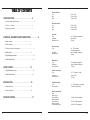
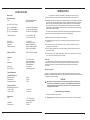
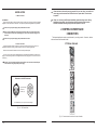
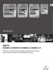
USER'S MANUAL
IMPORTANT SAFETY SYMBOLS
CAUTION
NOTE:
RISK OF ELECTRIC SHOCK
DO NOT OPEN
The symbol is used to indicate that some hazardous live terminals are
involved within this apparatus, even under the normal operating conditions,
which may be sufficient to constitute the risk of electric shock ordeath.
The symbol is used in the service documentation to indicate that specific
component shall be replaced only by the component specified in that
documentation for safety reasons.
Protective grounding terminal
Alternating current/voltage
Hazardous live terminal
ON: Denotes the apparatus is turned on
OFF: Denotes the apparatus is turned off.
WARNING: Describes precautions that should be observed to prevent the danger
of injury or death to the operator.
CAUTION: Describes precautions that should be observed to prevent danger of
the apparatus.
IMPORTANT SAFETY INSTRUCTIONS
·Read these instructions.
·Keep these instructions.
·Heed all warning.
·Follow all instructions.
·Water & Moisture
The apparatus should be protected from moisture and
rain, can not used near water, for example: near bathtub, kitchen sink or a swimming pool, etc.
·Heat
The apparatus should be located away from the heat source such as radiators,
stoves or other appliances that produce heat.
20
·Ventilation
Do not block areas of ventilation opening. Failure to do could result in fire. Always
install accordance with the manufacturer's instructions.
·Object and Liquid Entry
Power supply
Power consumption
Mains voltage
USA/Canada
U.K./Australia
Europe
Japan
StudioMix 10:
StudioMix 12:
18 W
23 W
120 V~, 60 Hz, MXUL5 adapter
240 V~, 50 Hz, MXUK5 adapter
230 V~, 50 Hz, MXEU5 adapter
240 V~, 60 Hz, MXJP5 adapter
Dimenstions
STUDIOMIX 10
Dimensions (H x W x D)
weight (net)
STUDIOMIX 12
Dimensions (H x W x D)
weight (net)
47mm / 37.5mm x 240mm x 208mm
approx. 1.3 kg
Objects do not fall into and liquids are not spilled into the inside of the apparatus
for safety.
·Power Cord and Plug
Protect the power cord from being walked on or pinched particularly at plugs, convenience
receptacles, and the point where they exit from the apparatus.
Do not defeat the safety purpose of the polarized or grounding-type plug. A
polarized plug has two blades with one wider than the other. A grounding type
plug has two blades and a third grounding prong. The wide blade or the third
prong is provided for your safety. If the provided plug does not fit into your outlet,
refer to electrician for replacement.
·Power Supply
47mm / 37.5mm x 240mm x260mm
approx. 1.7 kg
The apparatus should be connected to the power supply only of the type as marked
on the apparatus or described in the manual. Failure to do could result in damage
to the product and possibly the user.
Unplug this apparatus during lightning storms or when unused for long periods
of time.
·Fuse
To prevent the risk of fire and damaging the unit, please use only of the
recommended fuse type as described in the manual. Before replacing the fuse,
make sure the unit turned off and disconnected from the AC outlet.
·Electrical Connection
Improper electrical wiring may invalidate the product warranty.
·Cleaning
Clean only with a dry cloth. Do not use any solvents such as benzol or alcohol.
·Servicing
Do not implement any servicing other than those means described in the manual.
Refer all servicing to qualified service personnel only.
·Only use accessories/attachments or parts recommended by the manufacturer.
Measuring conditions:
1:1kHz rel.to 0 dBu; 20 Hz - 20 kHz, line input; main output; unity gain.
2:20Hz - 20kHz; measured at main output. Channels1-4 unity gain: EQ flat; al channels on main mix;
channels 1/3 as far left as possible, channels 2/4 as far right as possible. Reference = +6 dBu.
As a result of these efforts, modifications may be made from time to existing products without prior notice.
Specifications and appearance may differ from those listed or illustrated.
19
·Warning
Please remember the high sound pressure do not only temporarily damage your
sense of hearing, but can also cause permanent damage. Be careful to select a
suitable volume.
TABLE OF CONTENTS
1.INTRODUCTION...................................................2
EQ mono channels
Low
Mid
High
80 Hz / 15 dB
2.5 kHz / 15 dB
12 kHz / 15 dB
EQ stereo channels
Low
Mid
High
80 Hz / 15 dB
2.5 kHz / 15 dB
12 kHz / 15 dB
Aux sends
Type
Impedance
Max.output level
1/4"TS connector, unbalanced
approx. 20 kΩ
+22 dBu
1.1 General mixing console functions.................................................................2
1.2 The user’ s manual..............................................................................3
1.3 Before you get started..........................................................................3
2.CONTROL ELEMENTS AND CONNECTORS .....................4
2.1 Mono channels..............................................................................4
2.2 Stereo channels.............................................................................6
2.3 Connector carry of the main section............................................................7
2.4 Main section ................................................................................9
2.5 Digital effects processor
2.6 Rear Panel Section
3.APPLICATION..................................................13
3.2 Rear Panel Section
Impedance
Max.input level
1/4" TRS connector,
electronically balanced
approx. 20 kΩ bal. /10 kΩ unbal.
+22 dBu
...................................................................11
........................................................................12
3.1 Digital effects processor
Stereo aux return
Type
.................................................................13
......................................................................14
4.INSTALLTION...................................................15
4.1 Mains connection............................................................................15
Main outputs
Type
Impedance
Max.output level
XLR electronically balanced
approx. 240Ω bal./ 120Ω unbal.
+28 dBu
Control room outputs
Type
Impedance
Max.output level
1/4"TS connector, unbal.
approx. 120 Ω
+22 dBu
Headphones output
Type
Max.output level
1/4"TRS connector, unbalanced
+19 dBu / 150Ω(+25 dBu)
4.2 Audio connections...........................................................................15
5.SPECIFICATIONS................................................17
1
Main mix system data2
Noise
Main mix @ -∞,
Channel fader -∞
Main mix @ 0 dB,
Channel fader -∞
Main mix @ 0 dB,
Channel fader @ 0 dB
-106 dB / -109 dB A-weighted
-95 dB / -98 dB A-weighted
-84 dB / -87 dB A-weighted
18
1.INTRODUCTION
5.SPECIFICATIONS
Congratulations! In purchasing the StudioMix 10 / StudioMix 12 series micing concole
you have acquired a mixing console whose small size belies its versatility and audio performance.
Mono inputs
Microphone inputs
Type
XLR, electronically balanced,
discrete input circuit
Mic E.I.N. (20 Hz - 20 kHz)
@ 0 Ω source resistance
@ 50 Ω source resistance
@ 150 Ω source resistance
Frequency response
-134 dB / 135.7 dB A-weighted
-131 dB / 133.3 dB A-weighted
-129 dB / 130.5 dB A-weighted
<10 Hz -150 kHz (-1 dB),
<10 Hz -200 kHz (-3 dB)
+10 to +60 dB
+12 dBu @ +10 dB gain
approx. 2.6 kΩ balanced
110 dB / 112 dB A-weighted
(0 dBu In @ +22 dB gain)
Gain range
Max. Input level
Impedance
Signal-to noise ratio
Distortion (THD+ N)
Line input
Type
Impedance
Gain range
Max. Input level
17
▲ 130dB dynamic range for an incredible amount of headroom
▲ A bandwidth ranging from below 10 Hz to over 200 KHz for crystal-clear reproduction of over the
finest nuances
▲ The extremely low-niose and distortion-free circuitry
transparent signal reproduction
guarantees absolution natural and
▲ They are perfectly matched to every conceivable microphone with up to 60 dB gain and +48 volt
phantom power supply
▲ They enable you to use the greatly extended dynamic range of your. 24-bit/192 kHz HD recorder
to the full. Thereby maintaining optimal audio quality
1/4" TRS connector,
electronically balanced
approx. 20Ω banlanced
10 kΩ unbanlanced
-10 to +40 dB
+22 dBu @ 0 dB Gain
“British EQ”
The equalizers used for the StudioMix Series are based on the legendary circuitry of top-notch
consoles made in Britain, which are renowned throughout the world for their incredibly warm and
musical sound character. Even with extreme gain settings these equalizers ensure outstanding
audio quality.
Fade-out attenuation
(Crosstalk attenuation)
Main fader closed
Channel muted
Channel fader closed
90 dB
89.5 dB
89 dB
Frequency response
Microphone input to main out
<10 Hz - 90 kHz
<10 Hz - 160 kHz
+0 dB / -1 dB
+0 dB / -3 dB
Impedance
Max. Input level
The microphone channels feature high-end ME Mic Preamps that compare well with costly outboard
preamps in terms of sound quality and dynamics and boast the following features.
0.005% / 0.004% A-weighted
1
Stereo inputs
Type
The StudioMix Series represents a milestone in the development of mixing console technology. With the ME
microphone preamps including phantom power as an option. Balanced line input and a powerful effects
section. The mixing consoles in the ME Series are optimally equipped for live and studio applications.
Owing to state-of-the-art circuitry your ME console produces a warm analog sound that is unrivalled.
With the addition of the latest digital technology these base-in-class consoles combine the advantages
of both analog and digital technology.
Multi-effects processor
which give your 100 presets producing first-class reverb, delay and modulation effects plus numerous
Additionally, your StudioMix mixing console has an effects processor with 24-bit A/D converters included,
multi-effects in excellent audio quality.
CAUTION!
We should like to draw your attention to the fact that extreme volumes may damage your
hearing and/or your headphones or loudspeakers. Turn the MAIN MIX control and phones
control in the main section fully down before you switch on the unit. Always be careful to
set appropriate volume levels.
1.1 general mixing console functions
A mixing console fulfils three main functions:
1/4" TRS connector,
electronically balanced
approx. 20 kΩ
+22 dBu
▲
Signal processing: Preamplification, level adjustment, mixing of effects. Frequency equalization.
2
Unbalanced use of
1/4"TRS connector
▲
Signal distribution: Summing of signals to the aux sends for effects processing and monitor mix,
distribution to one or several recording tracks, power amp(s), control room and 2-track outputs.
▲ Mix: Setting the volume level, frequency distribution and positioning of the individual signals in the
stereo field, level control of the total mix to match the recording devices/crossover/power
amplifier(s). All other mixer functions can be included in this main function.
strain relief clamp
sleeve
sleeve
tip
ground shield
signal
tip
1.2 The user’ s manual
The user’ s manual is designed to give you both an overview of the controls, as well as detailed information
on how to use them.
The foot switch connects the two poles momentarily
the block diagram supplied with the mixing console gives you an overview of the connections
between the inputs and outputs, as well as the associated switches and controls.
For the moment, just try and trace the signal path from the microphone input to the FX send connector,
Do not be put off by the huge range of possibilities; it is easier than you thank! if you look at quickly familiarize
yourself with your mixing console and you will soon be making the most of all its many possibilities.
Fig. 4.2: 1/4"mono plug
Balanced use of
1/4"TRS connector
1.3 Before you get started
strain relief clamp
Your mixing console was carefully packed in the factory to guarantee safe transport. Nevertheless,
we recommend that you careful examine the packing and its contents for any signs of physical damage.
Which may have occurred during transit.
tip
sleeve
1.3.1 Shipment
hot (+ ve)
ground shield
sleeve
ring
ring
cold (- ve)
tip
If the unit is damaged, please do NOT return it to us, but notify your dealer and the shipping
company immediately, otherwise claims for damage or replacement may not be granted.
to assure optimal protection of your ME during use or transports, we recommend utilizing a
carrying case.
Please always use the original packing to avoid damage due to storage or shipping.
Never let unsupervised children play with the ME or with its packaging.
For connection of balanced and unbalanced plus,
rig and sleeve have to be bridged at the stereo plug
Fig. 4.3: 1/4"
stereo plug
Please dispose of all packaging materials in an environmentally-fiendly fashion.
Headphones connection
with 1/4" TRS connector
1.3.2 Initial operation
Be sure that there is enough space around the unit for cooling purposes and to avoid over-heating please
do not place your mixing console on high-temperature devices such as radiators or power amps. The
console is connected to the mains via the supplied cable. The console meets the required safety standards.
Blown fuses must only be replaced by fuses of the same type and rating.
never connect the ME to the power supply unit when the latter is connected to the mains! First
connect the power supply unit to the console, then connect the power supply unit to the mains.
strain relief clamp
tip
sleeve
left signal
ground shield
sleeve
ring
ring
tip
right signal
Fig. 4.4: Stereo plug for headphones connection
3
16
Please note that all unit must be properly grounded. For your own safety, you should never
remove any ground connectors from electrical devices or power cables, or render them
inoperative.
4.INSTALLATION
4.1 Mains connection
AC POWER IN
Connect the power supply to the 3-pin mains connector on the rear of the console. Use the AC adapter
supplied to connect the console to the mains. The adapter complies with all applicable safety standards.
Please use only the power supply unit provided with the console.
Never connect the ME to the power supply unit while the latter is connected to the mains!
First connect the console to the power supply unit, then connect the power supply unit to
the mains.
Please sure that only qualified people install and operate the mixing console. During
installation and operation, the user must have sufficient electrical contact to earth,
otherwise electrostatic discharges might affect the operation of the unit.
2.CONTROL ELEMENTS AND
CONNECTORS
This chapter describes the various control elements of your mixing console. All controls, switches
and connectors will be discussed in detail.
Please use only the power supply unit provided with the console.
2.1 Mono channels
4.2 Audio connections
You will need a larger number of cable for the various connections to and from the console. The
illustrations below show. The wing of these cables. Be sure to use only high-grade cable.
1
2
Please use commercial RCA cables to wire the 2-track inputs and outputs.
1
3
You can, of course, also connect unbalanced devices to the balanced input/outputs. Use either mono
plugs, or ensure that ring and sleeve are bridged inside the stereo plug (or pins 1 & 3 in the case of XLR
connectors).
MIC
LINE
IN
BAL
OR
UNBAL
Caution! Never use unbalanced XLR connectors (PIN 1 and 3 connected) on the MIC input
connectors when using the phantom power supply.
TRIM
dB/dBu
+10 +10 -40+60
EQ
0
HIGH
12 KHz
-15
Balanced use with XLR connectors
+15
0
MID
2.5 KHz
-15
+15
0
LOW
1
2
3
1=groud / shield
2=hot (+ve)
3=cold (-ve)
80 Hz
1
2
-15
+15
3
LOW CUT
75Hz
18 dB/Oct
0
FX
-
8
Output
Input
+15
PAN
For unbalanced use pin 1 and pin 3 have to be bridged
CLIP
L
R
0
-
8
Fig. 4.1: XLR connections
+15
LEVEL
1
Fig. 2.1: Connectors and controls on the mono channels
15
4
3.2 Live sound
MIC
Each mono input channel offers a balanced microphone input via the XLR connector and also
features switchable +48 V phantom power supply for condenser microphones. The StudioMix preamps
provide undistorted and noised-free gain as is typically known only from costly outboard preamps.
CD player
keyboard
TAPE
Please mute your play back system before you active the phantom power supply to prevent
switch-on thumps being directed to your loudspeakers. Please also note the instructions in
chapter 2.4“Main section”.
LINE IN
Each mono input also features a balanced line input on a
(mono jacks) can also be connected to these inputs.
Active Speaker
microphone
MD recorder
1/4 connector. Unbalanced devices
please remember that you can only use either the microphone or the line input of a
channel at any one time. You can never use both simultaneously!
2
3
4
MAIN OUT
L
1
2
2
1
3
1
MIC
MIC
LINE
IN
BAL
OR
UNBAL
LINE
IN
BAL
OR
UNBAL
TRIM
dB/dBu
LINE IN 5/6
MIC
LINE
IN
BAL
OR
UNBAL
TRIM
CTRL ROOM OUT
L
R
R
1
3
MIC
LINE
IN
The scale has 2 different value range: the first value range (+10 to +60 dB) refers to the MIC input and
shows the amplification for the signals fed in there.
2
3
3
dB/dBu
TRIM
dB/dBu
dB/dBu
LINE IN 7/8
MONO
BAL
OR
UNBAL
EQ
0
HIGH
-15
0
0
+15
EQ
0
0
MID
2.5 KHz
2.5 KHz
0
+15
PHANTOM
CLP
-3
-6
-10
-15
-20
PHONES
MID
0
R
-15
0
L
TAPE
TO CTRL
2.5 KHz
-15
PHONES
R
TAPE
TO MIX
CD/TAPE
12 KHz
+15
MID
+15
R
HIGH
-15
2.5 KHz
-15
L
BAL
OR
UNBAL
+15
-
OUT
88
PITCH
REVERB 00-39
ER/DLY 40-59
MULTI
MOD
60-73
R
IN
24-BIT DUAL ENGINE DSP
POWER +48 V
CLIP
24-BIT A/D & D/A CONVERTER
6
0
FX
TO CTRL
PROGRAM
(PUSH)
0 +15
0
74-79
80-99
20
L
R
FX SENDS
LOW
LOW
LOW
LOW
80 Hz
80 Hz
80 Hz
80 Hz
+15
-15
+15
LOW CUT
75Hz
18 dB/Oct
-15
+15
LOW CUT
75Hz
18 dB/Oct
0
-15
-
LOW CUT
75Hz
18 dB/Oct
0
FX
+15
LOW CUT
75Hz
18 dB/Oct
0
10
+4
-10
0
FX
+4
-10
0
FX
+15
+4
-10
0
FX
8
-15
+4
-10
0
FX
0
0
FX
FX
FX
+15
-
+15
PAN
-
+15
BAL
-
+15
BAL
-
8
PAN
8
+15
8
PAN
8
+15
8
PAN
8
+15
8
8
10
-
+15
BAL
BAL
15
20
CLIP
L
CLIP
R
0
L
0
CLIP
R
L
0
CLIP
R
L
0
CLIP
R
L
0
CLIP
R
L
0
CLIP
R
L
0
CLIP
R
L
0
R
25
30
1
2
+15
LEVEL
3
-
+15
LEVEL
4
-
+15
LEVEL
5/6
-
+15
LEVEL
7/8
-
+15
LEVEL
9/10
-
8
-
8
+15
LEVEL
8
-
8
+15
LEVEL
8
8
40
60
-
8
The circuitry of the British EQs is based on the technology used in the bast-known top-of-the-line consoles
and providing a warm sound without any unwanted side effects. The result are extremely musical equalizes
which, unlike simple equalizers, cause no side effects such as phase shifting or bandwidth limitation, even
with extreme gain settings of +15 dB.
EQ
12 KHz
-15
MID
+15
0
0
+15
MONO
L
BAL
OR
UNBAL
+10 +10 -40+60
HIGH
12 KHz
-15
+15
0
HIGH
12 KHz
Guitar
EQ
All mono input channels include a 3-band equalizer. All bands provide boost or cut of up to 15 dB. In the
central position, the equalizer is inactive.
EQ
0
-15
+10 +10 -40+60
8
The second value range (+10 to +60 dB) refers to the line input and shows its sensitivity. The settings
for equipment with standard line-level signals (-10dB or +4dBu) look like this: While the TRIM control is
turned all the way down, connect your equipment. Set the TRIM control is turned to the external devices
standard output level. If that unit that an output signal level display, it should show 0 dB during signal
peaks. For +4 dBu, turn up TRIM sightly. for -10 dBV a bit more. Tweaking is done using the CLIP LED.
+10 +10 -40+60
Headphone
SEND FX
LINE IN 11/12
MONO
L
BAL
OR
UNBAL
R
+10 +10 -40+60
LINE IN9/10
MONO
L
BAL
OR
UNBAL
TRIM
8
1
2
8
TRIM
Use the TRIM control to adjust the input gain. This control should always be turned fully counterclock
-wise whenever you connect or disconnect a signal source to one of the inputs.
+15
LEVEL
11/12
MAIN MIX
The upper (HI) and the lower band (LO) are shelving filters that increase or decrease all frequencies above
or below their cut-off frequency. The cut-off frequencies of the upper and lower band are 12 kHz and 80 Hz
respectively. The mid band (602/802/1002/1202) is configured as a peak filter with a center frequency of
2.5kHz
+6.66
.
LOW CUT
In addition, the mono channels are equipped with a steep LOW CUT filter (slope at 18 dB/oct., -3 dB at 75 Hz)
designed to eliminate unwanted low-frequenty signal components. These can be noise created by band-held
microphones, subsonic noise or plosive sounds created by highly sensitive microphones.
FX
FX sends enable you to feed signals via a variable control from one or more channels and sum these signals
to bus. The bus appears at the console’s FX send output and can be fed from there to an external effects device.
The return from the effects unit is then brought back into the console on the aux return connectors or normal
channel inputs. Each FX send is mono and features up to +15 dB gain.
5
MIDI sound module
Fig. 3.2: Live application of the StudioMix console
14
3. APPLICATION
As the name suggests, the FX sends of the ME mixing consoles are intended to drive effects devices (reverb,
delay, etc.) and are therefore configured post-fader. This means that the mix between dry signal and effect
remains at the level determined by the channel’s aux send, irrespective of the level fader setting. If this were
not the case, the effects signal of the channel would remain audible even when the fader is lowered to zero.
With ME mixing consoles the channel fader is called LEVEL control.
3.1 Recording studio
CD player
TAPE
In the StudioMIX 10/StudioMix 12, the FX send is routed directly to the built-in effects processor. To
make sure that the effects processor receives an input signal, you should not turn this control all the way to
the left (-∞ ).
keyboard
Active monitor
MD recorder
microphone
PAN
The PAN control determines the position of channel signal within the stereo image. This control features a
constant-power characteristic, which means the signal is always maintained at a constant level, irrespective
of position in the stereo panorama.
LEVEL
The LEVEL control determines the level of the channel signal in the main mix
Attention: Since the FX path for the effect processor is connected post-fader, the LEVEL
control has to be turned up in order to get this channels signal to the effects processor!
1
2
MAIN OUT
L
2
1
2
CTRL ROOM OUT
L
R
R
1
3
ME1002 FX
3
HIGH QUALITY 14 INPUT 2/2 BUS MIXER 24-BIT DSP FX PROCESSOR
MIC
LINE IN 3/4
MIC
LINE
IN
LINE
IN
BAL
OR
UNBAL
BAL
OR
UNBAL
TRIM
TRIM
dB/dBu
dB/dBu
LINE IN 5/6
MONO
L
BAL
OR
UNBAL
EQ
0
HIGH
HIGH
12 KHz
+15
0
-15
0
R
R
CLP
-3
-6
-10
-15
-20
PHONES
TAPE
TO CTRL
+15
IN
88
REVERB 00-39
PITCH
ER/DLY 40-59
MULTI
MOD
60-73
-
OUT
24-BIT DUAL ENGINE DSP
POWER +48 V
CLIP
LOW
L
8
+4
-10
0
L
BAL
OR
UNBAL
L
BAL
OR
UNBAL
+4
-10
0
FX
+15
+4
-10
0
FX
L
BAL
OR
UNBAL
10
+15
LOW CUT
75Hz
18 dB/Oct
0
MONO
R
BAL
OR
UNBAL
80 Hz
-15
LOW CUT
75Hz
18 dB/Oct
LINE IN 9/10
MONO
20
L
LOW
80 Hz
+15
LINE IN 7/8
MONO
0
74-79
80-99
PROGRAM
(PUSH)
0 +15
FX SENDS
-15
LINE IN 5/6
MONO
6
24-BIT A/D & D/A CONVERTER
0
FX
TO CTRL
R
2.5 KHz
0
PHANTOM
L
MID
-15
LINE IN 3/4
TAPE
TO MIX
CD/TAPE
+15
MID
+15
0
R
PHONES
2.2 Stereo channels
12 KHz
2.5 KHz
-15
L
BAL
OR
UNBAL
8
-15
Guitar
L
BAL
OR
UNBAL
+10 +10 -40+60
EQ
0
Headphone
MONO
L
BAL
OR
UNBAL
SEND FX
LINE IN 9/10
MONO
R
+10 +10 -40+60
LINE IN 7/8
MONO
CLIP
The CLIP LED”s of the mono channels illuminate when the input signal is driven too high, which could
cause distortion. If this happens, use the TRIM control to reduce the preamp level until the LED does not
light anymore.
+4
-10
0
FX
R
0
0
FX
FX
R
R
R
FX
R
-
+15
L
R
PAN
-
+15
L
R
BAL
-
+15
L
R
BAL
-
8
+15
L
8
PAN
8
R
8
+15
L
8
-
8
10
+15
L
R
BAL
BAL
15
20
CLIP
0
CLIP
0
CLIP
0
CLIP
0
CLIP
0
CLIP
0
25
+4
-10
30
+4
-10
+4
-10
+4
-10
+15
LEVEL
3/4
-
+15
LEVEL
5/6
-
+15
LEVEL
7/8
-
0
8
-
+15
LEVEL
9/10
0
0
0
MAIN MIX
+15
FX
-
8
-
8
FX
+15
BAL
L
0
-
+15
BAL
CLIP
+6.66
.
FX
L
0
-
+15
BAL
CLIP
R
FX
8
2
8
+15
LEVEL
8
-
8
1
8
+15
LEVEL
8
-
8
8
40
60
BAL
CLIP
R
L
0
CLIP
R
L
0
R
3/4
Digital Audio workstation
+15
LEVEL
5/6
-
+15
LEVEL
7/8
-
8
-
8
+15
LEVEL
8
-
8
MIDI sound module
+15
LEVEL
9/10
Fig. 2.2: Connectors and controls on the stereo channels
Fig. 3.1: the StudioMix in a recording studio
13
6
LINE IN
2.6 Rear Panel Section
Each stereo channel has two balanced line level input on 1/4” connectors for left and right channels. If
only the connector marked “L”(left) is used, the channel operates in mono. Stereo channels are designed
to handle typical line level signals. Both inputs will also accept unbalanced connectors.
COAXIAL
COAXIAL
OPTIC
A stereo EQ is highly preferable to two mono equalizers. when working on a stereo signal, as two
separate Eq”s will usually produce an unwanted discrepancy between the left and right channels.
FX
The FX sends of the stereo channels function similar to those of the mono channels. However, since the FX send
buses are both mono, a mono sum is a first taken from the stereo input before it is sent to the FX bus.
1
2
3
BAL
The BAL(ANCE) control determines the levels of left and right input signals relative to each other before
both signal are then routed to the main stereo mix bus. If a channel is operated in mono via the line input,
the control has the same function as the PAN control used in the mono channels.
LEVEL
The LEVEL control determines the level of the channel signal in the main mix
+4/-10
The stereo inputs of the StudioMix 10 and StudioMix 12 have an input sensitivity switch which selects
between +4 dBu and -10 dBv At -10 dBV (home-recording level), the input is more sensitive (requires
less level to drive it) than at +4 dBu (studio level).
DIGITAL
OUTPUT
DIGITAL
INPUT
AC POWER IN
Fig. 2.6: Rear Panel Section(with UD)
AC POWER IN
Connect to the assembled power adaptor
USB SOCKET
USB record and playback will work if it is connected with computer
COAXIAL DIGITAL OUTPUT
To output digital signal when it is recorded, and for digital decode equipment's use
2.3 Connector carry of the main section
COAXIAL DIGITAL INPUT
Connect with DVD or other digital coaxial signal output equipment, for digital signal's coaxial record
MAIN OUT
L
R
CD/TAPE
CTRL ROOM OUT
L
R
SEND FX
PUT SWITCH
Optical and coaxial signal record switch over on-off
OPTICAL INTERFACE
Connect with DVD or other optical signal output equipment, for digital signal's optical record
L
PHONES
R
IN
OUT
Fig. 2.3: Connectors of the main section
FX SEND
The FX SEND connector outputs the signal you picked up from the individual using the FX controls. You
can connect this to the input of an external effects device order to process the FX bus master signal. Once
an effects mix is created, the processed signal can then be routed from the effects devices outputs back into
a stereo input
7
12
2.5 Digital effects processor
CLP
-3
-6
-10
-15
-20
24-BIT DUAL ENGINE DSP
88
24-BIT A/D & D/A CONVERTER
REVERB 00-39
PITCH
74-79
ER/DLY 40-59
MULTI
80-89
MOD
60-73
AMB 90-99
PROGRAM
(PUSH)
0
-
8
FX SENDS
+15
Fig. 2.5: Effects section
100 FIRST-CLASS EFFECTS
The StudioMix 10 / StudioMix 12 features a built-in digital stereo effects processor. This effects
processor offers a large number of standard effects such as Hall, Chorus, Flanger, Delay and various
combination effects. Using the FX control, you can feed signals into the effects processor. The integrated
effects module has the advantage of requiring no wiring. This way, the danger of creating ground loops or
uneven signal levels is eliminated at the output, completely simplifying the handing.
SIGNAL and CLIP LED
The SIGNAL LED on the effects module shows the presence of a signal whose level is high enough. This
LED should always be on. However, make sure that the CLIP LED lights up only sporadically.
If it is constantly, you are overdriving thr effects processor, which leads to unpleasant distortion.
If this occurs, turn the FX controls down somewhat.
PROGRAM
The PROGRAM control has two functions: by turning the PROGRAM control, you dialed the number of
an effect. The number of the preset you just dialed up blinks in the display. To confirm your selection, press
the PROGRAM control; the blinking stops.
FX TO MAIN
The FX TO MAIN control feeds the effects signal into the main mix. If the control is turned all the way
counterclockwise, no effects signal is present in the signal of the mixing console.
If the connected effects processor receives no input signal. the FX SEND control is probably too
low. This also goes for the built-in effects processor.
Adjust your external effects processor to 100% wet (effects signal only), before the effects signal
is added to the main mix along with “dry” channel signals.
In this instance, the FX control of the channel being used as an effects return should be turned
fully counterclockwise. otherwise feedback problems can occur!
PHONES/CONTROL ROOM OUT
The stereo PHONES connector (at the top of the connector panel) is where you connect headphones.
The unbalanced CTRL ROOM OUT connector carry the summed effects and main mix signals, as well
as soloed channel signals. The PHONE/CONTROL ROOM control adjusts the level of both headphones
and main monitor outputs.
MAIN OUT
The MAIN OUT connectors are unbalanced mono connector . The main mix signal appears here at a level
of 0 dBu. The MAIN MIX fader adjusts the volume of these outputs. Depending on how you wish to use your
mixer and which gear you own, you can connect the following equipment.
LIVE PA SYSTEMS:
A stereo dynamics processor (optional), stereo equalizer (optional) and the stereo power amplifier for
full-range loudspeakers with passive crossovers.
If you wish to use multi-way loudspeaker systems without an integrated crossovers. Active crossovers
are impiemented directly before the power amplifier, and they divide the frequency range into several
segments that are first amplified in the amplifiers and then passed on to the corresponding
RECORDING
For mastering using a stereo compressor can be recommended. Use it to custom-tailor the dynamic
characteristics of you signal to the dynamic range of the recording equipment you are using. The signal is
in the case passed on from the compressor into the recorder.
CD/TAPE INPUT
The CD/TAPE INPUTS are used to bring an external signal source (e.g. CD player, tape deck, etc.)
into the console. They can also be used as a standard stereo line input, so the output of a second ME.
Alternatively the line or tape output of a hi-fi amplifier with source selection switch could also be hooked
up here, allowing you to easily listen to additional sources.
The appendix contains an overview of all presets of the multi effects processor.
TAPE OUTPUT
These connectors are laid out RCA connectors and are wired parallel with the MAIN OUT. Connect the
inputs of a computer sound card or a recorder here. The output signal level is setup using the highly accurate
MAIN MIX fader .
11
8
2.4 Main section
POWER +48 V
CLIP
6
0
20
TAPE
TO MIX
TAPE
TO CTRL
PHANTOM
R
10
0
FX
TO CTRL
L
8
0
-
+15
10
LEVEL SETTING
To correctly set the gains of the channels, first set the LEVEL controls of the input channels to their center
positions (0 dB) Then use the TRIM controls to increase the input amplification until signal peaks show 0 dB
on the level meter.
When recording to digital recorders, the recorder s peak meter should not go into overload. While analog
recorders can be overloaded to some extent, creating only a certain amount of distortion (which is common
and often desirable), digital recorders distort quickly when overloaded. In addition, digital distortion is not only
undesirable, but also renders your recording completely useless.
When recording to an analog device. the VU meters of the recording machine should reach approx. +3 dB
with low-frequency signals (e.g. kick drum). Due to their inertia VU meters tend to display too low a signal level
at frequencies above 1 kHz. This is why, for example, a Hi-Hat should only be driven as far as -10 dB. Since
drums should be driven to approx 0 dB.
The peak meters of your ME display the level virtually independent of frequency. A recording
level of 0 dB is recommended for all signal types.
MAIN MIX
Use the MAIN MIX fader to adjust the volume of the main out.
15
20
25
PHONE/CONTROL ROOM
Use the PHONE/CONTROL ROOM control to adjust the signal level of the CONTROL ROOM and PHONES
outputs.
30
8
40
60
CD/TAPE TO MIX
When the TAPE TO MIX switch is depressed, the 2-track input is assigned to the main mix providing
an additional input for tape machines, MIDI instruments or other signal sources that do not require any
processing.
MAIN MIX
Fig. 2.4: Control elements of the main section
+48 V
The red +48 V LED lights up when phantom power is turned on. Phantom power is required to operate
condenser microphones and is activates using the +48 V switch located above the +48 V LED.
Caution! You must never use unbalanced XLR connectors (PIN 1 to 3 connected) on the
MIC input connectors if you want to use the phantom power supply.
Please do not connect microphones to the mixer (or the stagebox/wallbox) as long as the
phantom power supply in switched on. Connect the micro-Phones before you switch on
the power supply. IN addition, the monitor/PA loudspeakers should be muted before you
activate the phantom power supply. After switching on, wait approx. one minute in order
to allow system stabilization.
CD/TAPE TO CTRL
Press the CD/TAPE TO CTRL ROOM/PHONES switch if you want to monitor the 2-track input via the CTRL
ROOM OUT. This provides an easy way to monitor signals coming back from tape to ensure that they are
recording correctly.
If you are recording a signal via the CD/TAPE OUTPUT and wish to listen to this simultaneously via
the CD/TAPE INPUT, do not use the CD/TAPE TO MIX switch. Doing this would create a feedback
loop, since the signal would be routed, via the main mix, back to tape via the CD/TAPE OUTPUT.
To monitor the CD/TAPE INPUT, use the CD/TAPE TO CTRL ROOM switch to assign the tape signal
to the monitor(s) or headphones. This will avoid the tape signal being routed to the CD/TAPE
OUTPUT.
FX TO CTRL
If you want to monitor only the FX send signal in your headphones or monitor speaker(s), press the
FX TO CTRL switch. Now the signal of the effects processor can be monitored alone, and the main mix
and/or CD/tape signal is no longer present on the phone and control room outputs.
POWER
The blue POWER LED indicates that the console in powered on.
LEVEL INDICATOR
The high-precision 4-segment display accurately displays the relevant signal level.
9
10