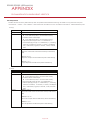
1
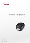
EZ2250i/EZ2350i BARCODE PRINTER USER MANUAL User Manual : EZ2250i series Version : Rev. E Issue Date : 2013.11.28 P/N : 920-014611-00 1 EZ2250i/EZ2350i USER MANUAL CONTENTS 1. BOX CONTENT ............................................................................ 1 1.1 Box Content ............................................................................................................... 1 1.2 Getting to Know Your Printer .................................................................................. 2 2. PRINTER SETUP ............................................................................. 4 2-1. Loading the label roll ................................................................................................... 4 2-2. Loading the ribbon....................................................................................................... 7 2-3. Connecting the printer to the host computer .......................................................... 8 2.4 Installing Printer Driver and GoLabel with Super Wizard CD ................................ 9 3. PRINTER SETTING AND CONTROL ............................................. 14 3-1. Operation Panel ......................................................................................................... 14 3-2. LCD Interface Introduction ....................................................................................... 15 3-3 LAN Setting ................................................................................................................... 20 3-4 LCD Password .............................................................................................................. 22 3-5. LCD Interface Function .............................................................................................. 24 3-6. Label Calibration and Self Test ................................................................................. 28 3-7. Dump mode ................................................................................................................ 30 3-8. Error Alerts .................................................................................................................... 31 3-9. USB Host ....................................................................................................................... 33 4. NETSETTING FOR ETHERNET ....................................................... 35 4-1. Installing the NetSetting software ............................................................................. 35 4-2. The Interface of NetSetting ....................................................................................... 36 5. ACCESSORIES ........................................................................... 43 5-1. Internal rewinder......................................................................................................... 43 5-2. Installing the rewinder guide ..................................................................................... 45 5-3. Label dispenser ........................................................................................................... 46 5-4. Installing the cutter ..................................................................................................... 48 5-5. Installing the Parallel adapter ................................................................................... 50 6. MAINTENANCE AND ADJUSTMENT .......................................... 52 6-1. Installing / removing the print head module .......................................................... 52 6-2. Adjusting the print line ............................................................................................... 53 6-3. Adjusting the ribbon tension ..................................................................................... 54 6-4. Cleaning the thermal print head ............................................................................. 55 6-5. Adjusting the balance and print head tension ...................................................... 56 6-6. Ribbon shield settings ................................................................................................. 57 6-7. Cutter settings ............................................................................................................. 58 6-8. Troubleshooting .......................................................................................................... 59 APPENDIX Contents Contents EZ2250i/EZ2350i USER MANUAL FCC COMPLIANCE STATEMENT FOR AMERICAN USERS This equipment has been tested and found to comply with the limits for a CLASS A digital device, pursuant to Part 15 of the FCC Rules. These limits are designed to provide reasonable protection against harmful interference when the equipment is operated in a commercial environment. This equipment generates, uses, and can radiate radio frequency energy and, if not installed and used in accordance with the instructions, may cause harmful interference to radio communications. Operation of this equipment in a residential area is likely to cause harmful interference in which case the user will be required to correct the interference at own expense. EMS AND EMI COMPLIANCE STATEMENT FOR EUROPEAN USERS This equipment has been tested and passed with the requirements relating to electromagnetic compatibility based on the standards EN 55022:2010 Class A, EN61000-3-2:2006/ A1:2009/A2:2009, EN 61000-3-3:2008 and EN 55024:2010, IEC 61000-4-2:2008 series The equipment also tested and passed in accordance with the European Standard EN55022 for theboth Radiated and Conducted emissions limits. EZ2250i SERIES TO WHICH THIS DECLARATION RELATES IS IN CONFORMITY WITH THE FOLLOWING STANDARDS IEC 60950-1:2005(2nd Edition)+Am 1:2009, GB4943-2001 GB9254-2008(Class A) GB17625.1-2003, EN 55022:2010 Class A, EN61000-3-2:2006/ A1:2009/A2:2009, EN 61000-3-3:2008 and EN 55024:2010, IEC 61000-4-2:2008 series, CAN/CSA C22.2 No. 60950-1-03, date July, 2006, UL 60950-1, 1st Edition, 2007-10-31, CFR 47, Part 15 WARNING This is a Class A product. In a domestic environment this product may cause radio interference in which case the user may be required to take adequate measures. 此为Class A产品,在生活环境中,该产品可能造成无线电干扰,在这种情况下,可能需要用户对其干扰采取切实可行 的措施。 Decleration Declaration EZ2250i/EZ2350i USER MANUAL SAFETY INSTRUCTIONS Please read the following instructions carefully. 1. Keep the equipment away from humidity. 2. Before you connect the equipment to the power outlet, please check the voltage of the power source. 3. Make sure the printer is off before plugging the power connector into the power jack. 4. It is recommended that you connect the printer to a surge protector to prevent possible transient overvoltage damage. 5. Be careful not to get liquid on the equipment to avoid electrical shock. 6. For safety and warranty reasons, ONLY qualified service personnel should open the equipment. 7. Do not repair or adjust energized equipment under any circumstances. Caution **** Danger of explosion if battery is incorrectly replaced. Replace only with the equivalent type recommended by the manufacturer. **** Dispose of used batteries according to the manufacturer’s instructions. **** Only use with designated power supply adapter model. **** Changes or modifications not expressly approved by the party responsible for compliance could void the user's authority to operate the equipment. Specifications are subject to change without notice. Safety instructions Safety instructions 1 Barcode Printer 1.1 Box Content Please check that all of the following items are included with your printer. EZ2250i/EZ2350i Barcode Printer Label Stock USB Cable EZ2250i Series Quick Guide Ribbon Module Empty Ribbon Core s 0i Serie i/EZ235 EZ2250 Power Adapter Power Cord Ribbon CD Including GoLabel software and EZ2250i/EZ2350i user manual. 1 1 Barcode Printer 1.2 Getting to Know Your Printer External view 1. 2. 3. 4. Operator panel Lower cover plate Viewing window Printer cover 1 2 3 4 5 6 7 8 9 10 11 1. 2. 3. 4. 5. 6. 7. 8. 9. 10. 11. Feed slot for continuous labels Auto-Calibration button Parallel port (optional) Applicator interface (optional) USB Host N Ethernet port USB port Serial port (DB-9) Power jack On/Off switch Feed slot for continuous labels 2 1 Barcode Printer Internal view 1. 2. 3. 4. 5. 6. 7. 8. 9. 10. 11. 12. Ribbon rewind hub Ribbon supply hub Print mechanism Platen roller Tear-off plate Release lever for print head Adjustment wheel for sensor Paper guide Label tension guide Label supply hub Label roll guide Release catch 1 1. Movable sensor 3 2 Printer Setup 2.1 Loading the label roll This printer supports the following printing methods: Thermal transfer printing (TTP):Requires a ribbon for transferring a printed image to a medium. Direct thermal printing (DTP):Does not require a ribbon, only thermal paper. Please check which printing method you are using and alter the settings accordingly in the printer driver, printer menu, and/or software. 1. Place the printer on a flat surface and open the printer cover. 2. Pull out the print head release lever as shown in the illustration (1) and turn it anticlockwise to a top right position (2). 3. Pull the release catch for the label roll guide to the right as shown by the blue arrow 1. 4. 2 Now slide the label roll guide forward and fold it up as shown by the blue arrow 2. 1 4 2 Printer Setup 5. Place the label roll on the label supply hub, pushing it right up to the printer housing. (Do not apply too much pressure to avoid damaging the label stock.) 6. Fold the label roll guide back down and push it against the label roll. 【Note】 When moving the label roll guide, hold it only by the end that is attached to the bracket, not by its top. 7. Load the label roll into the printer as shown in the illustration. Pass it through the printer as indicated by the blue arrows. 8. Pass the label stock through the sensor and up to the tear-off plate. 3 【Note】 Remember to set the movable sensor to gap, black mark, or tag hole by changing the position of the sensor with the adjustment wheel. 2 5 1 2 Printer Setup 9. The labels pass between the wall of the printer housing and the adjustable paper guide. 【Note】 Pass the labels through the printer as shown in the illustration. 10. Return the print head release lever to its original position. 11. Then close the printer cover. 6 2 Printer Setup 2.2 Loading the Ribbon 1. Place the printer on a flat surface and open the printer cover. 2. Pull out the print head release lever as shown in the illustration (1) and turn it anticlockwise to a top right position (2). 3. Place a new ribbon on the ribbon supply hub. Then place an empty ribbon core on the ribbon rewind hub. 4. The two illustrations on the right show you how to install the ribbon depending on the ribbon type (ink side in or out). Ink side out 5. Pass the ribbon under the print head and back up on the other side. Attach it to the empty ribbon core. 【Note】 Do not pass the ribbon under the sensor. 7 Ink side in 2 Printer Setup 2.3 Connecting the Printer to the Host Computer 1. Please make sure that the printer is switched off. 2. Connect the power cord to the AC adapter and connect the adapter to the printer. 3. Connect the USB cable to the printer and host computer. 4. Switch on the printer. The operator panel should now light up. 8 2 Printer Setup 2.4 Installing Printer Driver and GoLabel with Super Wizard CD 1. Insert the Super Wizard CD in the CD/DVD drive of the host computer and the program should pop up automatically. You will see the Welcome screen first. On the Welcome screen, choose “Standard Installation”. 2. The wizard will then ask you to make sure your USB and power cables are connected and that the power is turned on. Make sure that is done and then click “Next”. 3. The next screen you will see is, “Install the GoLabel Software and Windows driver”. Click “Next” to continue. Notice * If the Super Wizard program did not run automatically, you can either turn on the “Auto-run” setting for your CD/DVD driver or double-click the icon of CD/DVD driver to run the program. 9 2 Printer Setup 4. As the printer driver and GoLabel are installing, a screen will display a progress bar. 5. Once the installation is complete, you can start to make and print labels with GoLabel or throug the printer driver. 6. As the optional steps, you can also print a test label or register your printer during the “Standard Installation” procedure. Notice * If you need more resources, tools or reference documents, you can also find them on Super Wizard CD. Just click “Other Choices” on Welcome Screen to access the files. 10 2 Printer Setup Installing Printer Driver Directly from CD Folder 1. Insert the product CD in the CD/DVD drive of the host computer and open the "Seagull Drivers" folder on the CD. Select the icon for the driver file and click it to start the installation. 2. Follow the instructions on the screen. The Driver Wizard guides you through the installation procedure. Select "Install printer drivers". 3. Specify your printer model. Godex EZ2250i 11 2 Printer Setup 4. Specify the port used to connect the printer to the host computer. 5. Enter a printer name and assign the appropriate rights. Godex EZ2250i Godex EZ2250i 6. Once the installation is complete, a summary of the printer settings is displayed. Check whether the printer settings are correct and click "Finish" to start copying the driver files. Wait until copying is complete, then finish the installation. Godex EZ2250i Godex EZ2250i 12 2 7. Printer Setup Once the driver installation is complete, the new printer should appear in the "Printers and Faxes" folder. Godex EZ2250i Godex EZ2250i 13 3 Printer Setting and Control 3.1 Operation Panel Operation Panel Introduction LCD SCREEN OPERATION PANEL DIRECTION KEY FEED BUTTON POWER BUTTON POWER Button Press the POWER button to turn on the printer, and the START UP SCREEN appears. The printer is on “ready to print” status, the LCD screen should display the message “READY“ on the screen. When printer is turned on, keep pressing the POWER button for 3 second will turn the printer off. FEED Button When you press the FEED button, the printer moves the label to the defined stop position. If you are using continuous labels, pressing the FEED button will move label stock until you release the button again. If you are using individual labels, pressing the FEED button will move only one label. If the label does not stop at the correct position, you need to run the auto-detection function on the label stock, please see Section 3.6 Label Calibration and Self Test. PAUSE PRINTING_FEED Button Pressing the FEED button while the printer is in standby mode will set the printer to pause mode. In this mode, the printer can receive commands, but it can only process them when it is reset to standby mode. Pressing the FEED button again will reset the printer to standby mode. Pressing the FEED button during printing will interrupt printing. When the PFEED button is pressed again, the printer resumes printing. Example: While a 10-label print job is running, you press the FEED button to pause the printer. Two of the labels have been printed. To resume printing and print the remaining eight labels, you press the FEED button again. CANCEL PRINTING_FEED Button Pressing the FEED button over 3 seconds during printing cancels a print job. The current print job is cancelled. Example: While a 10-label print job is running, you press the FEED button. Two of the labels have been printed. The print job is cancelled and the remaining eight labels are not printed. 14 3 Setting and Control for Operation Panel 3.2 LCD Interface Introduction Getting Started Press the POWER button to turn on the printer, and the START UP SCREEN appears. Power on If the printer is on “ready to print” status, the LCD screen should display the message “Ready“ on the screen. Please keep pressing button and wait for the timer to be filled, then the LCD interface will enter into the MAIN PAGE for SETTING MODE. You can make various setting functions in SETTING MODE. Enter Main page 15 3 Setting and Control for Operation Panel Operations on Setting Page On MAIN PAGE, press or button to move the cursor and select the functions. Select a designated function and press FEED button, you will enter the SETTING PAGES for the function. Select or Enter On SETTING PAGES, press or button to select the setting items. Select a designated function and press FEED button, you will enter the SETTING VALUE PAGES for the function. Select or Enter 16 3 Setting and Control for Operation Panel On SETTING VALUE PAGES, press or button to change the setting values. Select or Press FEED button will apply the setting value you just selected, and the red tick will appear to mark the value. Apply **** The blue arrow indicates the value you are selected. **** The red tick indicates that the selected value is applied now. 17 3 Setting and Control for Operation Panel Exit from Current Page to Ready Status The icon on top-left corner displays the capture of upper level screen and also guides you back to upper level with left or up arrow. NAVIGATION ICON On SETTING VALUE PAGES, press button will go back to the upper level screen. Back to the Setting page On SETTING PAGES, press button will go back to the MAIN PAGE screen. Back to the Main page 18 3 Setting and Control for Operation Panel On MAIN PAGE, select the “EXIT” icon and press the FEED button to exit from SETTING MODE and the printer goes back to READY status. EXIT from Setting Mode or Back to the Ready status 19 3 Setting and Control for Operation Panel 3.3 LAN Setting Operations on Setting Page On MAIN PAGE,press or button to move the cursor and select the functions. Select a designated function and press FEED button, you will enter the SETTING PAGES for the function. Select Device or Device Enter LAN Setting On LAN Setting PAGE,press or button to select the setting items. Select a designated funcition or Select DHCP and press FEED button, you will be able to setup DHCP function 20 3 Setting and Control for Operation Panel The default of DHCP is Disable. ,Press or button to change the setting values. Select to enable DHCP Press FEED button twice to save the setting. Press FEED once to exit. Press FEED again to save and return to previous SETTING PAGE. 21 3 Setting and Control for Operation Panel 3.4 LCD Password Operations on Setting Page On MAIN PAGE, press or button to move the cursor and select the functions. Seclect a designated function and press FEED button, you will enter the SETTING PAGE for the function. Select Device or Device Enter LCD Password The default of LCD Setting is Disable. Press or button to change the setting values. Select button to Enable Password function 22 3 Setting and Control for Operation Panel Select button again to setup the password Press FEED button twice to svae the setting Press FEED button onece to exit. Press FEED button again to save and reture to previous SETTING PAGE 23 3 Setting and Control for Operation Panel 3.5 LCD Interface Function Main Page Printer Setting Setting items for printer, ex. Printing speed, darkness. Also includes a Printing Wizard for your ease of printing. Setting items for printing label, ex. Rotation, Printing position offset. Label Setting Option modules and connection port settings. Device Self-Diagnose functions for printer, ex. TPH testing, self-test page printing. Analysis Exit from Setting Mode. Exit 24 3 Setting and Control for Operation Panel Setting Items in Setting Mode English Deutsch 繁體中文 简体中文 Français Español German 日本語 Italiano Pусский Türk 2-5 or 7 0-19 Label with Gaps Label with Marks Continuous Direct Thermal Thermat Transfer 0-40 0-19 2-5 or 7 LCD Language Printer Setting Speed Darkness Wizard Media Type Printer Mode Tear-off Position Darkness Speed Media Detection Sensor Media Type Direct Thermal Thermat Transfer 0-40 Apply Cancel 850 852 437 860 863 865 857 861 862 855 866 737 851 869 Win 1252 Win 1250 Win 1251 Win 1253 Win 1254 Win 1255 Win 1257 Printing Mode Tear-off Position Top of Form Setting Codepage 0° 90° 180° 270° -100 - 100 -100 - 100 -100 - 100 001 Form Name 002 Form Name Rotation Label Setting Horizental Offset Vertical Offset Start Offset Recall Label 25 Auto Select See-Through Reflective Label with Gaps Label with Marks Continuous 3 Setting and Control for Operation Panel Buzzer Device Optional Setting LAN Setting LCD Password Serial Port Setting RTC Setting Apply Cancel None Cutter Option Label Dispensor Applicator Apply Pre-Printing Cancel 09100 Part NO. Disable DHCP Enable Default Gateway 192.168.000.254 192.168.102.076 Dynamic IP 255.255.255.000 Subnet Mask Disable Enable 4800 bps 9600 bps 19200 bps Baud Rate 38400 bps 57600 bps 115200 bps Non Parity Odd Even 7 bits Data bits 8 bits 1 bits Stop bits 2 bits Apply Clock Display Cancel YYYY/MM/DD RTC Setting HH:MM:SS Calibration Self-test Analysis TPH Testing Reset to Default Label Format Graphic Clear Memory Bitmap Fonts True Type Fonts Asian Fonts ALL Exit Exit 26 Apply Cancel Apply Cancel Apply Cancel Apply Cancel Apply Cancel Apply Cancel Apply Cancel Apply Cancel Apply Cancel Apply Cancel 3 Setting and Control for Operation Panel Status of LCD Interface When printer is on standby status (ready to print), the LCD interface will display “Ready” on screen. You can only print on this “Ready“ status. If there is any printers error, the LCD screen will display the error screen to show the type of error. You can fix the error according the notice. WARNING ICON ERROR ICON Check Ribbon ERROR DESCRIPTION Icon Definition To upper level To upper level Lock Unlock Scroll the value Appears on the NAVIGATION ICON of Setting Pages. It guides you back to upper level by pressing “LEFT“ key. Appears on the NAVIGATION ICON of Setting Value Pages. It guides you back to upper level by pressing “UP“ key. On Setting Value pages, press “RIGTH“ key to lock the value for preventing unexpected change. For locked value, press “RIGHT” key again to unlock the value. On Setting Value pages, press “UP“ or “DOWN“ key to scroll the values for your selection. 27 3 Setting and Control for Operation Panel 3.6 Label Calibration and Self Test Label Calibration The printer can automatically detect and store label height. That means the host computer does not need to transmit the label height to the printer. Self Test Self-test function lets you check whether the printer is functioning normally. Here is how you run the label size calibration and self test. 1. Check that the label stock is loaded correctly. 2. Turn off the printer. 3. Turn the printer on again, keeping the FEED button pressed. When the LED starts to flash red, release the FEED button. The printer will now measure the label stock and store the label height. 4. Once the printer has successfully measured the label stock, it will print a self-test label. The contents of a self-test printout are listed below. Model & Version USB ID setting Serial port setting MAC address of Ethernet port IP protocol setting IP address of Ethernet port EZ2250i:GX.XXX USB S/N:12345678 Serial port:96,N,8,1 MAC Addr:xx-xx-xx-xx-xx-xx DHCP Enable IP xxx.xxx.xxx.xxx Gateway setting Gateway xxx.xxx.xxx.xxx Netmask setting Sub-Mask xxx.xxx.xxx.xxx ################################## Number of DRAM installed 1 DRAM installed Image buffer size Image buffer size:1500 KB Number of forms 0000 FORM(S) IN MEMORY Number of graphics Number of fonts 0000 GRAPHIC(S) IN MEMORY 000 FONT(S) IN MEMORY Number of Asian fonts 000 ASIAN FONT(S) IN MEMORY Number of Databases 000 DATABASE(S) IN MEMORY Number of Scalable fonts Free memory size Speed, Density, Ref. Point, Print direction 000 TTF(S) IN MEMORY 4073 KB FREE MEMORY ^S4 ^H8 ^R000 ~R200 Label width, Form length, Stop position ^W102 ^Q100,3 ^E18 Cutter, Label Dispenser, Mode Option:^D0 ^O0 ^AD Sensor Setting Code Page Reflective AD:1.96 2.84 2.49[0.88_23] Code Page:850 28 3 Setting and Control for Operation Panel Label Calibration Button A hardware button to make a Label Calibration while printer encountering ‘’Media Error’’ during the cases when first-time printer start up or change label or ribbon to another type, such as change using gap label to continuous or black mark labels. CALIBRATION BUTTON Press Press C-button for 2 seconds, it will make an auto-sensing to calibrate the label and ribbon’s parameters. Press ****Press C-button is equivalent to the auto-sensing command ‘’~S,SENSOR’’ that will cancel on-printing-job and make the Label Calibration immediately. 29 3 Setting and Control for Operation Panel 3.7 Dump mode If the label settings do not match the printer output, you can switch the printer to dump mode to check whether an error has occurred during the transfer between printer and host computer. In dump mode, the unprocessed raw data are sent to the printer and printed. This shows you quickly whether any data are sent to the printer at all. Here is how you switch to dump mode: 1. Switch off the printer. 2. Switch on the printer and keep the FEED button pressed. 3. You will hear 3 beeps first and then one beep later. Release the FEED button after the last beep. The printer will automatically print "Dump Mode Begin". That means the printer is now in dump mode. 4. Send commands to the printer and check whether they match the printer output. To exit dump mode, press the FEED button. The printer will automatically print "Out Of Dump Mode" and switch to standby mode. Alternatively, you can switch off the printer to exit dump mode. 30 3 Setting and Control for Operation Panel 3.8 Error Alerts In the event of a problem that prevents normal functioning of the printer, you will see an error message on LCD screen and hear some beep signals. Please refer to below table for the error alerts. LCD SCREEN OPERATION PANEL DIRECTION KEY FEED BUTTON POWER BUTTON Operation Panel Status Type Beeps Description Solution Print Head Error 2 x 4 beeps The printing mechanism is not correctly closed. Open the print mechanism and close it again. Print Head Error None High temperature at the print head. Once the print head has cooled down, the printer switches to standby mode. No ribbon is installed and the printer displays an error. Make sure that the printer is set to direct thermal printing mode. The ribbon is finished or the label supply hub is not moving. Replace the ribbon roll. No paper is detected. Make sure that the label sensor is positioned correctly. If the sensor still does not detect the paper, run the auto-detection function again. Paper is finished. Replace the label roll. Printer feed problem. Possible reasons: the print medium has become trapped around the rubber roll; the sensor cannot detect a gap or black mark between the labels; there is no paper. Please reset the sensor. Printhead up (Open) Media Error 2 x 3 beeps Check Ribbon Media Error 2 x 2 beeps Check Media 31 3 Setting and Control for Operation Panel Operation Panel Status Type Beeps Description Solution The memory is full. The printer Delete unnecessary data or install prints the message "File System full additional memory. ". File Error Use the "~X4" command to print Unable to find file. The printer all files. Then check whether the 2 x 2 beeps prints the message "File Name not files exist and whether the names found" are correct. A file of the same name already exists. The printer prints the message "Duplicate Name". 32 Change the name of the file and try storing it again. 3 Setting and Control for Operation Panel 3.9 USB Host Definition : USB Host port supports either device:USB memory stick, keyboard or scanner. Purpose USB memory stick : It extends the user memory space up to 32GB for Graphic, Font, Label Format, DBF and Command files downloading. The printer’s Firmware also can be updating if copy new version of Firmware into USB memory stick. Connecting an USB keyboard to printer for ‘’ Standalone’’ mode operation. Plug-in an USB scanner to operate the printer in ‘’Standalone’’ mode. Usage of Extended Memory USB memory stick : It supports hot-plugging function; printer will create a Folder ‘’\LABELDIR’’ and switch ‘’User Flash’’ to ‘’ Extended Memory‘’ automatically while user plugs an USB memory stick into a GoDEX ‘’i’’ model printer. Connect the USB Stick plugged -in printer to PC via USB Device or Ethernet port and run ‘’GoLabel’’ software to download Graphic, Font, Label Format, DBF and Command files to the printer. Detail download procedures, please refer to ‘’GoLabel On-line Help’’. Usage of Firmware Update Remove USB memory stick from printer and plug-in it to a PC’s USB port; delete Firmware ‘’*.bin’’ file from ‘’\LABELDIR\FW’’ of USB memory stick if it existing; or create a Folder ‘’\LABELDIR\FW’’ to USB memory stick if it doesn’t existing. Copy a new version of Firmware ‘’xxxx.bin’’ to the Folder ‘’\LABELDIR\FW’’; and then remove USB and plug-in back to the printer that going to update Firmware. The printer will update the Firmware automatically when plug-it-into the printer and printer find-out the Firmware in ‘’\LABELDIR\FW’’ is newer version. Don’t remove the USB memory stick out while it’s under updating with ‘’Flash Writing...’’message that displays on LCD panel. 33 3 Setting and Control for Operation Panel USB Keyboard When plug-in an USB keyboard to the printer, LCD panel will display “Standalone Mode”, press the “Enter” key on keyboard and “Feed” key in the printer to entering to the dialog for “Recall Label” operation. Only the sub-dialog “Recall Label” is able operating by keyboard as follow definition: 1. Press “ESC” key to exist from “Standalone Mode” or back to previous dialog 2. Press “F1”, it will let the printer from “Ready” mode entering into “Standalone Mode” 3. Press “Enter”, “Arrow” and “Alphabetic” keys as the usual in PC that will perform the key-in function of “Recall Label” in “Standalone Mode”. Scanner When plug-in an USB scanner to the printer, LCD panel will display “Standalone Mode”, press the “Feed” key in the printer to entering the dialog of “Recall Label” operation. User performs the “Recall Label” function interactively through the LCD panel, 4 direction keys, Feed key and Scanner. Scanner is using in “standalone Mode” to scanning the “Serial Number, Variable” and Print Quantity while the printer prompts a message on LCD panel and wait for data input. ** The USB Host port on ‘’i’’ ‘’x’’ model printer is without ‘’HUB’’ function. ** The USB Memory Stick supports with ‘’FAT32’’Disk Format and up to 32GB only. The certified venders are Transcend, Apacer, Patriot, Consair and Kingston. * The download function for Graphic, Font, Label Format, DBF and Command files is operated by GoLabel of PC and must go through the a ‘’i’’ ‘’x’’ model printer itself. * On a PC, user may copy entire folder’’\LABELDIR’’ from USB memory stick to PC or vice-versa. Copy a sub-folder or individual file in ‘’\LABELDIR’’ to PC or vice-versa is not supported. 34 4 NetSetting for Ethernet 4.1 Installing the NetSetting software The NetSetting software is used to manage the network configurations when connecting the printer via Ethernet port. It is available on product CD or can be downloaded from official website. To install the NetSetting, please follow below steps. 1. Insert the product CD in the CD/DVD drive of the host computer and open the "Ethernet" folder on the CD. 2. Select the icon for the NetSetting installation file and click it to start the installation. 3. Follow the instructions on the screen. The Setup Wizard guides you through the installation procedure. 4. Specify the “Installation Folder". 5. Click ”Next” to start the installation. 6. Once the installation is completed; you will see the NetSetting icon on your desktop. 35 4 NetSetting for Ethernet 4.2 The Interface of NetSetting Click the NetSetting icon to start the program; you will see the start page as below. The start page will display the basic information of connected printer and your PC. RT700i Click the magnifier icon to search the Godex printers which are connected via Ethernet port in you network environment. Once a connected Godex printer is detected, it will be listed on the start page. There are six tabs on the top of interface which can configure different types of network settings. But for the data security reason, you need correct password to enter the configuration pages. **** The default password is “1111”, you can change the password later from the “IP Setting” tab. 36 4 NetSetting for Ethernet IP Setting The IP Setting tab can change the printer name, Port number, Gateway setting and the password for configuring the printer. You can also set the printer’s IP address ether by DHCP or by Static IP. You can press “Set” button to apply the settings and “ReGet” button to refresh the setting values. **** To fully benefit from the NetSetting software, you should be familiar with basic networking principles. Please contact your network administrator for related network setting information. 37 4 NetSetting for Ethernet Alert Path Setting NetSetting will send the alert messages to designated mail account when the error happened on printer. The alert messages are sent by SMTP (Simple Mail Transfer Protocol) or SNMP (Simple Network Management Protocol). You can set or change the configurations of SMTP and SNMP on this “Alert Path Setting” tab. You can press “Set” button to apply the settings and “ReGet” button to refresh the setting values. 38 4 NetSetting for Ethernet Alert Message Setting For the alert message notification function, you can decide which error cases need to be sent out to the operator. Moreover, the alert messages can be set to be sent by SMTP, SNMP or both. You can press “Set” button to apply the settings and “ReGet” button to refresh the setting values. 39 4 NetSetting for Ethernet Printer Configuration Set or change the configurations of connected printer. Most of key settings for the printer operation can be done by this setting page. RT700i You can press “Set” button to apply the settings and “ReGet” button to refresh the setting values. 40 4 NetSetting for Ethernet User Command The “User Command” tab provides a communication interface for operator to control the printer. Input printer commands in "Input Command" window and press “Send Command” button, the commands will be sent to the printer. For some commands that will return response message, the message will be displayed in "Output Message" window. You can press “Send Command” button to send printer commands via Ethernet port and control the printer remotely. 41 4 NetSetting for Ethernet Firmware Download On “Firmware Download” tab, the current version of printer firmware will be showed on the screen. If you need to update the printer firmware, just specify the file location of firmware file and press “Start Download Firmware” button. The printer firmware then can be updated remotely. BOOT : 1.000a1 F/W : RT700i 1.000a In addition to the firmware update, you can press “Recover To Factory Settings” button to restore the printer configurations back to factory default. 42 5 Accessories 5.1 Internal rewinder 1 Rewinder 2 Retention clip 3 Screws (set of 4) 4 Rewinder guide 【Note】 Maximum height of the rewound medium: 118 mm 1 2 3 【Suggestion】 Medium thickness: 0.06 mm– 0.25 mm 1. 4 Place the printer on a flat surface and open the printer cover. 【Note】 Remember to switch off the printer before starting the installation. 2. Remove the cover for the rewinder module. 43 5 Accessories 3. Remove the retention clip from the rewinder. 4. Secure the rewinder on the printer housing using the four screws supplied. 2 1 5. Now connect the rewinder cable to the printer housing. 6. Installation of the rewinder module is now complete. 44 5 Accessories 5.2 Installing the rewinder guide 1. Unscrew the screw marked in the illustration on the front of the printer, which secures the lower cover plate. 2. Remove the lower cover plate. 【Note】 Switch off the printer before starting the installation. 3. Mount the rewinder guide on the print mechanism and secure it with screws. 4. Installation of the rewinder guide is now complete. 5. Now load the label stock. 6. Pass the label stock through the rewinder from the bottom up. Secure the label stock on the rewinder using the retention clip. 【Note】 Make sure you choose the correct rewind direction. 7. Close the printer cover to complete the installation. 【Note 1】 Before you start using the rewinder, please make sure that you have carried out all the steps as shown in the illustrations. 【Note 2】 To use the label dispenser, you have to remove the rewinder guide again. 45 5 Accessories 5.3 Label dispenser 1. Unscrew the screw marked in the illustration on the front of the printer, which secures the lower cover plate. 2. Remove the lower cover plate. 【Note】 Switch off the printer before starting the installation. 3. Place the printer the right way up again. 4. Pull out the print head release lever as shown in the illustration (1) and turn it anticlockwise to a top right position (2). 5. Remove the retention clip. 6. Now load the label roll into the printer. 1 2 【Note】 A label liner thickness of 0.06 mm ± 10%, a weight of 65 g/ ㎡ ± 6% and a label height of 20 mm are recommended. 【Suggestion】 When using the label dispenser, you should set the stop position (^E) to 12. 7. Strip a few labels off the label liner (approx. 400 mm). Then pass the label liner through the print mechanism and from the bottom up onto the rewinder. 46 3 5 Accessories 8. Wind the label liner around the rewinder and secure it using the retention clip. 9. Return the print head release lever to its original position. 【Note】 Please make sure that the label stock rewinds the right way onto the rewind hub. 10. Replace the lower cover plate on the printer and secure it with screws 11. Press the lower part of the stripper sensor to fold it out. 12. The sensor locks in a horizontal position. 13. Close the printer cover to complete installation of the dispenser. 3 47 1 2 5 Accessories 5.4 Installing the cutter 1 Cutter cover 2 Cutter module 3 Cable clips 4 Screws (set of 4) 【Note 1】 Remember to switch off the printer before installing the cutter. 【Note 2】 Do not use to cut adhesive labels! Glue residue will be left on the cutter blade and impair its functioning. The cutter has a blade life of 500,000 cuts when using paper weighing 160 g/m² and 250,000 cuts when using paper weighing 200 g/m². 1. Unscrew the screw marked in the illustration on the front of the printer, which secures the lower cover plate. Remove the lower cover plate. 2. Remove the two screws securing the tear-off plate, then remove the tear-off plate. 48 5 Accessories 3. Secure the cutter module on the printer housing using the screws. 4. Connect the cutter cable connector to the cutter jack on the printer. 5. Route the connection cable along the bottom of the printer housing using the cable clips. 6. Place the cutter cover over the cutter module and secure it using the screw you removed from the lower cover plate. 7. Now load the label roll into the printer and close the printer cover. 【Note 1】 Check whether the cutter function is enabled in the printer. 【Note 2】 Labels or paper should be at least 30 mm high. 【Suggestion】 After installation of the cutter module, set the stop position (^E) to 26. 49 5 Accessories 5.5 Installing the Parallel adapter 1 2 3 4 Parallel cable Parallel adapter Connection cable Screws (set of 2) 1 2 3 1. Check whether the printer is switched off. Place the printer on a flat surface and open the printer cover. 2. Unscrew the two screws marked in the illustration on the right and remove the left-hand side of the printer housing. 3. Unscrew the screws on the parallel port cover and remove the cover. 50 4 5 Accessories 4. Install the Parallel adapter in its place and secure it on the housing with screws. 5. Connect the 30-pin connection cable to the motherboard. 6. Replace the left-hand part of the printer housing and secure it with the screws you removed earlier. 7. Installation of the Parallel adapter is now complete. 51 6 Maintenance and Adjustment 6.1 Installing / removing the print head module 1. Open the printer cover. 【Note】 Remember to switch off the printer before removing the print head module. 2. Pull out the print head release lever as shown in the illustration (1) and turn it anticlockwise to a top right position (2). 3. Hold the print head module at the front and gently pull it out. 4. If you cannot remove the module by gently pulling it, use a screwdriver as shown in the illustration. 5. Hold the module at the front and slide it into the printer along the guide rails. Firmly press the module in so the contacts are fully connected. 52 6 Maintenance and Adjustment 6.2 Adjusting the print line Please contact your local dealer for technical support. 1. Open the printer cover. 2. Pull out the print head release lever as shown in the illustration (1) and turn it anticlockwise to a top right position (2). 3. TPH print line adjustment: When printing is slow or when printing on thick label stock, the print line must be moved to the front (in paper feed direction) for a better print result. Using a flat-head screwdriver, turn the screws clockwise to move the TPH forward. The two screws on the left and right must be adjusted to the same position to ensure the print line and feed roller are in parallel. One turn of the screw moves the print head by 0.5 mm. To keep track of the change in quality, you should adjust the screws by ¼ turn at a time. If no improvement is visible, gently turn the screws clockwise as far as possible, then restart the adjustment process from there. A 53 6 Maintenance and Adjustment 6.3 Adjusting the print line You can adjust the ribbon tension by turning the ribbon shaft knob (green wheel at the base of the ribbon supply hub – see illustration) clockwise or anticlockwise. There are 4 possible settings, which are marked on the knob of the ribbon rewind hub and the ribbon supply hub. When set to 1, the tension is highest, while the tension is lowest at 4. If the tension is so low that the ribbon does not move forward, you need to reduce the tension of the ribbon supply hub or increase the tension of the ribbon rewind hub. To set the tension, press in the knob and turn it clockwise or anticlockwise as required. Increasing the tension of the ribbon rewind hub will remove any wrinkling of the ribbon during printing, which results from the use of different ribbon materials. (For details about the wrinkling/creasing of ribbons, see Section 5-6.) - If you are using a very narrow ribbon, the printer may not move the label stock forward (particularly with a ribbon that is less than 2" wide). In that case, reduce the tension by turning the knob of the ribbon supply hub anticlockwise. If the tension is too high, the ribbon core may be crushed and thus impossible to remove. In that case, reduce the tension of the ribbon supply hub and the ribbon rewind hub by turning the knobs anticlockwise. 54 + 6 Maintenance and Adjustment 6.4 Cleaning the thermal print head Dirt on the print head or ribbon may result in inadequate print quality (no printed image on part of the label). The printer cover should therefore be kept closed whenever possible. Keeping dirt and dust away from the paper or labels ensures a good print quality and a longer lifespan of the print head. Here is how you clean the print head: 1. 2. 3. 4. 5. Switch off the printer. Open the printer cover. Remove the ribbon. Release the print head by turning the print head release lever. To remove any label residue or other dirt from the print head (see blue arrow), please use a soft lint-free cloth dipped in alcohol. 【Note 1】 The print head should be cleaned once a week. 【Note 2】 Please make sure that there are no metal fragments or other hard particles on the soft cloth used to clean the print head. 55 6 Maintenance and Adjustment 6.5 Adjusting the balance and print head tension 1. Open the printer side cover. 2. Pull out the print head release lever as shown in the illustration (1) and turn it anticlockwise to a top right position (2). When using a variety of label stock and ribbons, the ink may not be evenly distributed. If there is no printed image on one side of the paper, or the ribbon wrinkles, the print head pressure must be readjusted using the TPH spring boxes. 3. Move the TPH spring boxes as shown in the illustration to change the print head pressure. The wider the medium you are using, the further out the TPH spring boxes must be moved. If there is no quality improvement, you need to change the pressure on the TPH spring boxes. 4. Turning the screw clockwise increases the pressure, while turning it anticlockwise reduces the pressure. + 56 - 6 Maintenance and Adjustment 6.6 Ribbon shield settings 1. The use of different ribbon materials may cause wrinkling of the ribbon, which in turn affects the print result as illustrated by the examples in (a) and (b). To change the print quality, you can adjust the ribbon shield screws. If your print result looks like the example in (a), you need to turn ribbon shield screw A clockwise. If your print result looks like the example in (b), you need to turn ribbon shield screw B clockwise. (a) 2. (b) To keep track of the change in print quality, you should adjust the screws by half a turn at a time. Print a test page. If there is no improvement in the print result, turn the screw by another half turn. Do not turn the adjustment screw more than two full turns. 【Note】 If you adjust the screw by more than two full turns, the paper feed may no longer function correctly. In that case, unscrew the ribbon shield screws fully and restart the adjustment process. A 57 B 6 Maintenance and Adjustment 6.7 Cutter settings 1. Socket head screws for adjusting the cutter are located on both sides of the cutter. 2. In the event of a paper jam, the cutter will no longer function correctly. Switch off the printer and use a hex key (#M3) to turn the socket head screw. 3. Turn the key anticlockwise to remove the jammed paper. 4. When you have removed the jammed paper, you can switch the printer back on. The cutter will automatically reset. 【Note】 The label medium should be at least 30 mm long to ensure correct functioning of the cutter. 58 6 Maintenance and Adjustment 6.8 Troubleshooting Problem The printer is switched on but the LED does not light up. The LED lights up red and printing is interrupted. Solution ♦ Check the power supply. Please see the Section 2.4 ♦ Check the software settings (driver settings) or command codes. ♦ Look for the error alert in the table in Section 3.3. Error Alerts. ♦ Check whether the print mechanism is closed correctly. Please see the Section 3.3 The label stock passes through the printer but no image is printed. ♦ Please make sure that the label stock is loaded the right way up and that it is suitable material. ♦ Choose the correct printer driver. ♦ Choose the correct label stock and a suitable printing mode. ♦ Clear the paper jam. Remove any label material left on the thermal print head and clean the print head using a soft lint-free cloth dipped in alcohol. The label stock jams during printing. Please see the Section 6.1 There is no printed image on some parts of the label. There is no printed image on part of the label or the image is blurred. The printed image is positioned incorrectly. A label is missed out during printing. ♦ Check whether any label material or ribbon is stuck to the thermal print head. ♦ Check for errors in the application software. ♦ Check whether the starting position has been set incorrectly. ♦ Check the ribbon for wrinkles. ♦ Check the thermal print head for dust or other dirt. ♦ Use the internal “~T” command to check whether the thermal print head will carry out a complete print job. ♦ Check the quality of the print medium. ♦ Check whether there is paper or dust covering the sensor. ♦ Check whether the label stock is suitable. Contact your supplier. ♦ Check the paper guide settings. ♦ Check the label height setting. ♦ Check whether there is dust covering the sensor. ♦ Run the auto-detection function. Please see the Section 3.2 The printed image is blurred. ♦ Check the darkness setting. ♦ Check the thermal print head for dust or dirt. Please see the Section 6.1 The cutter does not cut off the labels in a straight line. ♦ Check whether the label stock is positioned straight. The cutter does not cut off the labels completely. ♦ Check whether the label is more than 0.2 mm thick. When using the cutter, the labels are not fed through or cut off incorrectly. ♦ Check whether the cutter has been correctly installed. ♦ Check whether the paper guides are functioning correctly. The label dispenser is not functioning normally. ♦ Check whether there is dust on the label dispenser. ♦ Check whether the label stock is positioned correctly. **** If any problems occur that are not described here, please contact your dealer. Appendix EZ2250i/EZ2350i USER MANUAL APPENDIX PRODUCT SPECIFICATIONS ****Specifications are subject to change without notice. All company and/or product names are trademarks and/or registered trademarks of their respective owners. * **Minimum print height and maximum print speed specification compliance can be dependent on non-standard material variables such as label type, thickness, spacing, liner construction, etc. Godex is pleased to test non-standard materials for minimum print height and maximum print speed capability. Appendix Appendix EZ2250i/EZ2350i USER MANUAL APPENDIX INTERFACE Parallel port Handshaking Interface cable Pinout Pin No. 1 2-9 10 11 12 13 14 15 16 17 18 19-30 31 32 33 34-35 36 : DSTB is sent to the printer, BUSY to the host computer : Parallel cable compatible with IBM computers : See below Function /Strobe Data 0-7 /Acknowledge Busy /Paper empty /Select /Auto-Linefeed N/C Signal Gnd Chassis Gnd +5V, max 500mA Signal Gnd /Initialize /Error Signal Ground N/C /Select-in Transmitter Computer / printer Computer Printer Printer Printer Printer Computer / printer Computer Computer / printer Printer Computer / printer Serial Port Default settings: Baud rate 9600, no parity, 8 data bits, 1 stop bit, XON/XOFF protocol and RTS/CTS RS232 Housing(9-pin to 9-pin) DB9 Socket 1 RXD 2 TXD 3 DTR 4 GND 5 DSR 6 RTS 7 CTS 8 RI 9 Computer 1 2 3 4 5 6 7 8 9 DB9 Plug +5V, max 500mA TXD RXD N/C GND RTS CTS RTS N/C Printer ****The total current to the serial port may not exceed 500mA. Appendix Appendix EZ2250i/EZ2350i USER MANUAL APPENDIX INTERFACE USB Connector Type : Pin NO. Function 1 VBUS Type B 2 D- 3 D+ 4 GND Internal interface UART1 wafer N.C TXD RXD CTS GND RTS E_MD RTS E_RST +5V GND +5V 1 2 3 4 5 6 7 8 9 10 11 12 1 2 3 4 5 6 7 8 9 10 11 12 Ethernet module N.C RXD TXD RTS GND CTS E_MD CTS E_RST +5V GND +5V UART2 wafer N.C TXD RXD CTS GND RTS N.C RTS N.C +5V GND +5V 1 2 3 4 5 6 7 8 9 10 11 12 1 2 3 4 5 6 7 8 9 10 11 12 Add-on module N.C RXD TXD RTS GND CTS N.C CTS N.C +5V GND +5V Appendix EZ2250i/EZ2350i USER MANUAL APPENDIX FILE MANIPULATION WHEN USING USB STICK File Manipulation The files in both devices (USB memory stick and printer internal Flash memory) are able to copy and move by the commands ‘’~MCPY’’ and ‘’MMOV’’ that sends from GoLabel on a PC via either connection - USB or Ethernet ports. Copy Syntax ~MCPY,s:o.x,d:o.x Description Copy file from USB memory stick to Flash memory, or vise-versa Parameter s = source device of stored object; “D” for USB memory stick; “F” for internal Flash memory d = destination device of stored object “D” for USB memory stick; “F” for internal Flash memory o = object name (file name); the name “o” is substituted for “*” x = extension (file type), the type “x” is substituted by ”*”, or following either one: D= database, A= Asia font, C= TTF font, E= Bit-Mapped font, F= label format, G= graphic, S= serial file, T= text, B= Unicode Table. Example ~MCPY,F:*.F,D:*.F (Copy entire “Label Format” files from Flash memory to USB memory stick) ~MCPY,D:*.G,F:*.G (Copy entire “Graphic” files from USB memory stick to Flash Memory) ~MCPY,D:*.*,F:*.* (Copy all object files from USB memory stick to Flash Memory) Move Syntax ~MMOV,s:o.x,d:o.x Description Move files from USB memory stick to Flash memory or vise-versa Parameter s = source device of stored object; “D” for USB memory stick; “F” for internal Flash memory d = destination device of stored object “D” for USB memory stick; “F” for internal Flash memory o = object name (file name); the name “o” is substituted for “*” x = extension (file type), the type “x” is substituted by ”*”, or following either one: D= database, A= Asia font, C= TTF font, E= Bit-Mapped font, F= label format, G= graphic, S= serial file, T= text, B= Unicode Table. Example ~MMOV,F:*.F,D:*.F (Move entire “Label Format” files from Flash memory to USB memory stick) ~MMOV,D:*.G,F:*.G (Move entire “Graphic” files from USB memory stick to Flash Memory) ~MMOV,D:*.*,F:*.* (Move all object files from USB memory stick to Flash Memory) Appendix