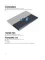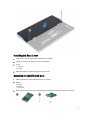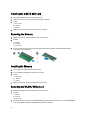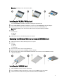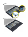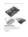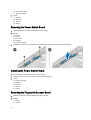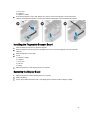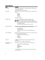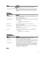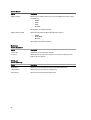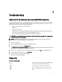
1
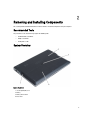
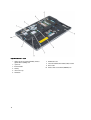
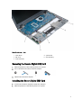
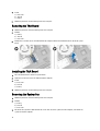
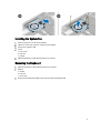
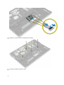
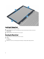
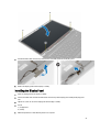
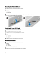
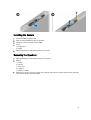
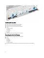
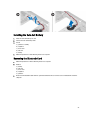
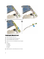
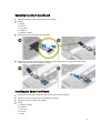
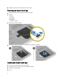
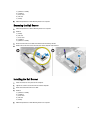
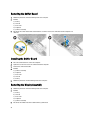
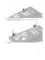
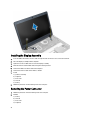
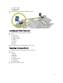
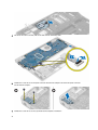
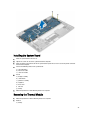
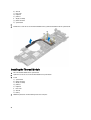
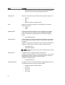
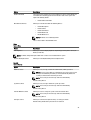
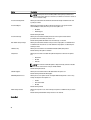
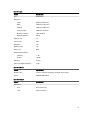
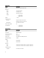
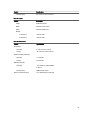
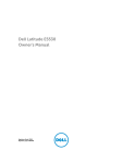
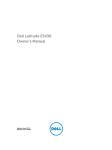
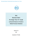
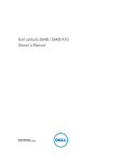
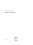
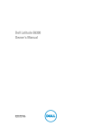
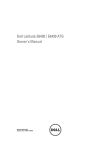
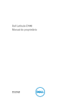
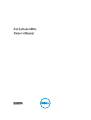
Dell Latitude 6430u
Owner's Manual
Regulatory Model: P36G
Regulatory Type: P36G001
Notes, Cautions, and Warnings
NOTE: A NOTE indicates important information that helps you make better use of your computer.
CAUTION: A CAUTION indicates either potential damage to hardware or loss of data and tells you how to avoid the
problem.
WARNING: A WARNING indicates a potential for property damage, personal injury, or death.
© 2013 Dell Inc.
Trademarks used in this text: Dell™, the Dell logo, Dell Boomi™, Dell Precision™ , OptiPlex™, Latitude™, PowerEdge™, PowerVault™,
PowerConnect™, OpenManage™, EqualLogic™, Compellent™, KACE™, FlexAddress™, Force10™ and Vostro™ are trademarks of Dell
Inc. Intel®, Pentium®, Xeon®, Core® and Celeron® are registered trademarks of Intel Corporation in the U.S. and other countries. AMD®
is a registered trademark and AMD Opteron™, AMD Phenom™ and AMD Sempron™ are trademarks of Advanced Micro Devices, Inc.
Microsoft®, Windows®, Windows Server®, Internet Explorer®, MS-DOS®, Windows Vista® and Active Directory® are either trademarks
or registered trademarks of Microsoft Corporation in the United States and/or other countries. Red Hat® and Red Hat®
Enterprise Linux® are registered trademarks of Red Hat, Inc. in the United States and/or other countries. Novell® and SUSE® are
registered trademarks of Novell Inc. in the United States and other countries. Oracle® is a registered trademark of Oracle Corporation
and/or its affiliates. Citrix®, Xen®, XenServer® and XenMotion® are either registered trademarks or trademarks of Citrix Systems, Inc. in
the United States and/or other countries. VMware®, vMotion®, vCenter®, vCenter SRM™ and vSphere® are registered trademarks or
trademarks of VMware, Inc. in the United States or other countries. IBM® is a registered trademark of International Business Machines
Corporation.
2013 - 05
Rev. A02
Contents
Notes, Cautions, and Warnings................................................................................................... 2
1 Working on Your Computer....................................................................................................... 7
Before Working Inside Your Computer.....................................................................................................................7
Turning Off Your Computer....................................................................................................................................... 8
After Working Inside Your Computer........................................................................................................................8
2 Removing and Installing Components..................................................................................... 9
Recommended Tools................................................................................................................................................ 9
System Overview...................................................................................................................................................... 9
Removing the Secure Digital (SD) Card..................................................................................................................11
Installing the Secure Digital (SD) Card................................................................................................................... 11
Removing the Battery............................................................................................................................................. 12
Installing the Battery.............................................................................................................................................. 12
Removing the Base Cover.......................................................................................................................................12
Installing the Base Cover........................................................................................................................................13
Removing the mSATA SSD Card.............................................................................................................................13
Installing the mSATA SSD Card..............................................................................................................................14
Removing the Memory............................................................................................................................................14
Installing the Memory.............................................................................................................................................14
Removing the WLAN / WiGig Card......................................................................................................................... 14
Installing the WLAN / WiGig Card.......................................................................................................................... 15
Removing the Wireless Wide Area network (WWAN) Card.................................................................................. 15
Installing the WWAN Card..................................................................................................................................... 15
Removing the TAA Board....................................................................................................................................... 16
Installing the TAA Board.........................................................................................................................................16
Removing the System Fan.......................................................................................................................................16
Installing the System Fan........................................................................................................................................17
Removing the Keyboard..........................................................................................................................................17
Installing the Keyboard...........................................................................................................................................19
Removing the Palmrest Assembly.......................................................................................................................... 19
Installing the Palmrest Assembly........................................................................................................................... 21
Removing the Power-Switch Board....................................................................................................................... 22
Installing the Power-Switch Board........................................................................................................................ 22
Removing the Fingerprint-Scanner Board..............................................................................................................22
Installing the Fingerprint-Scanner Board...............................................................................................................23
Removing the Display Bezel................................................................................................................................... 23
Installing the Display Bezel.....................................................................................................................................24
Removing the Display Panel................................................................................................................................... 24
Installing the Display Panel.................................................................................................................................... 25
Removing the Power LED Board.............................................................................................................................26
Installing the Power LED Board..............................................................................................................................26
Removing the Camera.............................................................................................................................................26
Installing the Camera..............................................................................................................................................27
Removing the Speakers.......................................................................................................................................... 27
Installing the Speakers........................................................................................................................................... 28
Removing the Coin-Cell Battery..............................................................................................................................28
Installing the Coin-Cell Battery...............................................................................................................................29
Removing the Bluetooth Card................................................................................................................................. 29
Installing the Bluetooth Card.................................................................................................................................. 30
Removing the Smart-Card Board............................................................................................................................31
Installing the Smart-Card Board.............................................................................................................................31
Removing the Smart-Card Cage............................................................................................................................. 32
Installing the Smart-Card Cage.............................................................................................................................. 32
Removing the Hall Sensor.......................................................................................................................................33
Installing the Hall Sensor........................................................................................................................................33
Removing the Sniffer Board....................................................................................................................................34
Installing the Sniffer Board.....................................................................................................................................34
Removing the Display Assembly.............................................................................................................................34
Installing the Display Assembly..............................................................................................................................36
Removing the Power Connector.............................................................................................................................36
Installing the Power Connector.............................................................................................................................. 37
Removing the System Board...................................................................................................................................37
Installing the System Board....................................................................................................................................39
Removing the Thermal Module...............................................................................................................................39
Installing the Thermal Module................................................................................................................................40
3 System Setup............................................................................................................................. 41
System Setup Overview..........................................................................................................................................41
Boot Sequence....................................................................................................................................................... 41
Navigation Keys......................................................................................................................................................41
Updating the BIOS ................................................................................................................................................. 42
System Setup Option.............................................................................................................................................. 43
4 Troubleshooting.........................................................................................................................51
Enhanced Pre-Boot System Assessment (ePSA) Diagnostics...............................................................................51
Diagnostics............................................................................................................................................................. 51
Beep Codes.............................................................................................................................................................52
LED Error Codes......................................................................................................................................................53
5 Specifications............................................................................................................................ 55
6 Getting Help................................................................................................................................61
Contacting Dell....................................................................................................................................................... 61
6
Working on Your Computer
1
Before Working Inside Your Computer
Use the following safety guidelines to help protect your computer from potential damage and to help to ensure your
personal safety. Unless otherwise noted, each procedure included in this document assumes that the following
conditions exist:
•
You have read the safety information that shipped with your computer.
•
A component can be replaced or--if purchased separately--installed by performing the removal procedure in
reverse order.
WARNING: Before working inside your computer, read the safety information that shipped with your computer. For
additional safety best practices information, see the Regulatory Compliance Homepage at www.dell.com/
regulatory_compliance
CAUTION: Many repairs may only be done by a certified service technician. You should only perform
troubleshooting and simple repairs as authorized in your product documentation, or as directed by the online or
telephone service and support team. Damage due to servicing that is not authorized by Dell is not covered by your
warranty. Read and follow the safety instructions that came with the product.
CAUTION: To avoid electrostatic discharge, ground yourself by using a wrist grounding strap or by periodically
touching an unpainted metal surface, such as a connector on the back of the computer.
CAUTION: Handle components and cards with care. Do not touch the components or contacts on a card. Hold a
card by its edges or by its metal mounting bracket. Hold a component such as a processor by its edges, not by its
pins.
CAUTION: When you disconnect a cable, pull on its connector or on its pull-tab, not on the cable itself. Some
cables have connectors with locking tabs; if you are disconnecting this type of cable, press in on the locking tabs
before you disconnect the cable. As you pull connectors apart, keep them evenly aligned to avoid bending any
connector pins. Also, before you connect a cable, ensure that both connectors are correctly oriented and aligned.
NOTE: The color of your computer and certain components may appear differently than shown in this document.
To avoid damaging your computer, perform the following steps before you begin working inside the computer.
1.
Ensure that your work surface is flat and clean to prevent the computer cover from being scratched.
2.
Turn off your computer (see Turning Off Your Computer).
CAUTION: To disconnect a network cable, first unplug the cable from your computer and then unplug the
cable from the network device.
3.
Disconnect all network cables from the computer.
4.
Disconnect your computer and all attached devices from their electrical outlets.
5.
Press and hold the power button while the computer is unplugged to ground the system board.
6.
Remove the cover.
7
CAUTION: Before touching anything inside your computer, ground yourself by touching an unpainted metal
surface, such as the metal at the back of the computer. While you work, periodically touch an unpainted metal
surface to dissipate static electricity, which could harm internal components.
Turning Off Your Computer
CAUTION: To avoid losing data, save and close all open files and exit all open programs before you turn off your
computer.
1.
Shut down the operating system:
–
In Windows 8:
*
Using a touch-enabled device:
a. Swipe in from the right edge of the screen, opening the Charms menu and select Settings.
b. Select the
*
and then select Shut down
Using a mouse:
a. Point to upper-right corner of the screen and click Settings.
b. Click the
–
and select Shut down.
In Windows 7:
1. Click Start
.
2. Click Shut Down.
or
1. Click Start
.
2. Click the arrow in the lower-right corner of the Start menu as shown below, and then click Shut
Down..
2.
Ensure that the computer and all attached devices are turned off. If your computer and attached devices did not
automatically turn off when you shut down your operating system, press and hold the power button for about 6
seconds to turn them off.
After Working Inside Your Computer
After you complete any replacement procedure, ensure you connect any external devices, cards, and cables before
turning on your computer.
1.
Replace the cover.
CAUTION: To connect a network cable, first plug the cable into the network device and then plug it into the
computer.
2.
Connect any telephone or network cables to your computer.
3.
Connect your computer and all attached devices to their electrical outlets.
4.
Turn on your computer.
5.
If required, verify that the computer works correctly by running the Dell Diagnostics.
8
Removing and Installing Components
2
This section provides detailed information on how to remove or install the components from your computer.
Recommended Tools
The procedures in this document may require the following tools:
•
Small flat-blade screwdriver
•
Phillips screwdriver
•
Small plastic scribe
System Overview
Figure 1. Back view
1.
2.
3.
4.
secure digital (SD) card
battery
battery release latch
base cover
9
Figure 2. Inside view — back
1. wireless local area network (WLAN) / wireless
gigabit alliance (WiGig) card
2. system fan
3. thermal module
4. memory
5. smart card cage
6. TAA board
10
7.
8.
9.
10.
mSATA SSD card
subscriber identification module (SIM) card slot
SD card slot
wireless wide area network (WWAN) card
Figure 3. Inside view — front
1. sniffer board
2. hall sensor
3. smart card board
4. system board
5. coin-cell battery
Removing the Secure Digital (SD) Card
1.
Follow the procedures in Before Working Inside Your Computer.
2.
Press in on the SD card to release it from the computer.
3.
Slide the SD card out of the computer.
Installing the Secure Digital (SD) Card
1.
Push the SD card into the compartment until it clicks into place.
2.
Follow the procedures in After Working Inside Your Computer.
11
Removing the Battery
1.
Follow the procedures in Before Working Inside Your Computer.
2.
Slide the release latch to unlock the battery, and slide to remove the battery from the computer.
Installing the Battery
1.
Slide the battery into its slot until it clicks into place.
2.
Follow the procedures in After Working Inside Your Computer.
Removing the Base Cover
1.
Follow the procedures in Before Working Inside Your Computer.
2.
Remove:
a) battery
b) SD card
3.
12
Remove the screws that secure the base cover to the computer, and slide the base cover and remove it.
Installing the Base Cover
1.
Place the base cover to align with the screw holes on the computer.
2.
Tighten the screws to secure the base cover to the computer.
3.
Install:
a) SD card
b) battery
4.
Follow the procedures in After Working Inside Your Computer.
Removing the mSATA SSD Card
1.
Follow the procedures in Before Working Inside Your Computer.
2.
Remove:
a) battery
b) SD card
c) base cover
3.
Remove the screw that secures the mSATA SSD card and remove the mSATA SSD card from the computer.
13
Installing the mSATA SSD Card
1.
Place the mSATA SSD card in its slot in the computer.
2.
Tighten the screw to secure the mSATA SSD card to the computer.
3.
Install:
a) base cover
b) SD card
c) battery
4.
Follow the procedures in After Working Inside Your Computer.
Removing the Memory
1.
Follow the procedures in Before Working Inside Your Computer.
2.
Remove:
a) battery
b) SD card
c) base cover
3.
Pry the securing clips away from the memory module until it pops up. Remove the memory module from its
connector on the system board.
Installing the Memory
1.
Insert the memory module into the memory socket.
2.
Press the memory module down until it clicks into place.
3.
Install:
a) base cover
b) SD card
c) battery
4.
Follow the procedures in After Working Inside Your Computer.
Removing the WLAN / WiGig Card
1.
Follow the procedures in Before Working Inside Your Computer.
2.
Remove:
a) battery
b) SD card
c) base cover
3.
14
Disconnect the antenna cables from the WLAN/WiGig card and remove the screw that secures the WLAN/WiGig
card to the computer. Remove the WLAN/WiGig card from the computer.
NOTE: The WiGig card has three antenna cables.
Installing the WLAN / WiGig Card
1.
Insert the WLAN/WiGig card into its connector at a 45–degree angle into its slot.
2.
Press the WLAN/WiGig card down and tighten the screw to secure the WLAN/WiGig card to the computer.
3.
Connect the antenna cables to their respective connectors marked on the WLAN/WiGig card.
NOTE: The WiGig card has three antenna cables that must be connected during installation.
4.
Install:
a) base cover
b) SD card
c) battery
5.
Follow the procedures in After Working Inside Your Computer.
Removing the Wireless Wide Area network (WWAN) Card
1.
Follow the procedures in Before Working Inside Your Computer.
2.
Remove:
a) battery
b) SD card
c) base cover
3.
Disconnect the antenna cables from the WWAN card.
4.
Remove the screw that secures the WWAN card to the computer.
5.
Disconnect the antenna cables from the WWAN card. Remove the screw that secures the WWAN card to the
computer and remove it.
Installing the WWAN Card
1.
Place the WWAN card in its slot in the system board.
2.
Press the WWAN card down and tighten the screw to secure the WWAN card to the computer.
3.
Connect the antenna cables to their respective connectors marked on the WWAN card.
15
4.
Install:
a) base cover
b) SD card
c) battery
5.
Follow the procedures in After Working Inside Your Computer.
Removing the TAA Board
1.
Follow the procedures in Before Working Inside Your Computer.
2.
Remove:
a) battery
b) SD card
c) base cover
3.
Remove the screw that secures the TAA board to the computer. Remove the TAA board from its slot on the system
board.
Installing the TAA Board
1.
Place the TAA board in its slot on the system board.
2.
Tighten the screw that secures the TAA board to the computer.
3.
Install:
a) base cover
b) SD card
c) battery
4.
Follow the procedures in After Working Inside Your Computer.
Removing the System Fan
1.
Follow the procedures in Before Working Inside Your Computer.
2.
Remove:
a) battery
b) SD card
c) base cover
3.
16
Disconnect the system fan cable. Remove the screws that secure the system fan to the computer, and remove the
system fan from the computer.
Installing the System Fan
1.
Place the system fan in its slot on the computer.
2.
Tighten the screws that secure the system fan to the computer.
3.
Connect the system fan cable.
4.
Install:
a) base cover
b) SD card
c) battery
5.
Follow the procedures in After Working Inside Your Computer.
Removing the Keyboard
1.
Follow the procedures in Before Working Inside Your Computer.
2.
Remove:
a) battery
b) SD card
c) base cover
3.
Disconnect the keyboard-backlight cable, trackstick cable, and keyboard cable.
17
4.
Remove the screws that secure the keyboard to the computer.
5.
Using a flat screwdriver, release the snaps.
18
6.
Flip the computer and remove the keyboard from the computer.
Installing the Keyboard
1.
Slide the keyboard into its compartment and ensure that it clicks into place.
2.
Flip the computer and tighten the screws to secure the keyboard.
3.
Connect the keyboard cable, keyboard-backlight cable and trackstick cable.
4.
Install:
a) base cover
b) SD card
c) battery
5.
Follow the procedures in After Working Inside Your Computer.
Removing the Palmrest Assembly
1.
Follow the procedures in Before Working Inside Your Computer.
2.
Remove:
a) battery
b) SD card
c) base cover
19
d) keyboard
3.
Disconnect the media-board cable, power-switch cable, touchpad cable, fingerprint-scanner cable and speaker
cable.
4.
Remove the screws that secure the palmrest assembly to the computer.
20
5.
Flip the computer and remove the screws that secure the palmrest assembly to the base of the computer and flip
open the lower assembly.
6.
Press against the sections to release the palmrest assembly and remove it from the computer.
Installing the Palmrest Assembly
1.
Align the palmrest assembly to its original position in the computer until it snaps into place.
2.
Tighten the screws to secure the palmrest assembly to the computer..
3.
Flip the computer and tighten the screws to secure the palmrest assembly to the computer.
4.
Tighten the screws to secure the palmrest assembly to the base of the computer.
5.
Connect the following cable:
a) Speaker cable
b) fingerprint-scanner cable
c) touchpad cable
21
d) power-switch cable
e) media-board cable
6.
Install:
a)
b)
c)
d)
keyboard
base cover
SD card
battery
Removing the Power-Switch Board
1.
Follow the procedures in Before Working Inside Your Computer.
2.
Remove:
a)
b)
c)
d)
e)
3.
battery
SD card
base cover
keyboard
palmrest assembly
Remove the screws that secure the power-switch board to the computer and remove it from the computer.
Installing the Power-Switch Board
1.
Place the power-switch board in its place on the computer.
2.
Tighten the screws to secure the power-switch board to the computer.
3.
Install:
a)
b)
c)
d)
e)
palmrest assembly
keyboard
base cover
SD card
battery
Removing the Fingerprint-Scanner Board
1.
Follow the procedures in Before Working Inside Your Computer.
2.
Remove:
a) battery
b) SD card
22
c) base cover
d) keyboard
e) palmrest assembly
3.
Un-route the fingerprint-scanner cable. Remove the screw that secures the fingerprint-scanner bracket to the
computer and remove the fingerprint-scanner bracket. Remove the fingerpint-scanner board from the computer
Installing the Fingerprint-Scanner Board
1.
Place the fingerprint-scanner in its slot on the computer.
2.
Place the fingerprint-scanner bracket on it and tighten the screw to secure the fingerprint-scanner bracket to the
computer.
3.
Route the fingerprint scanner cable.
4.
Install:
a)
b)
c)
d)
e)
5.
palmrest assembly
keyboard
base cover
SD card
battery
Follow the procedures in After Working Inside Your Computer.
Removing the Display Bezel
1.
Follow the procedures in Before Working Inside Your Computer.
2.
Remove the battery.
3.
Pry the sides and work around the corners of the display bezel and remove it from the display assembly.
23
Installing the Display Bezel
1.
Place the display bezel on the display assembly.
2.
Starting from the top corner, press on the display bezel and work around the entire bezel until it clicks onto the
display assembly.
3.
Install the battery.
4.
Follow the procedures in After Working Inside Your Computer.
Removing the Display Panel
1.
Follow the procedures in Before Working Inside Your Computer.
2.
Remove:
a) battery
b) display bezel
3.
24
Remove the screws that secure the display panel to the display assembly and flip the display panel over.
4.
Peel off the LVDS cable connector tape and disconnect the LVDS cable from the display panel.
5.
Remove the display panel from the display assembly.
Installing the Display Panel
1.
Place the display panel on the display assembly.
2.
Connect the LVDS cable and affix the LVDS cable connector tape to the display panel and flip the display panel
over.
3.
Tighten the screws to secure the display panel to the display assembly.
4.
Install:
a) display bezel
b) battery
5.
Follow the procedures in After Working Inside Your Computer.
25
Removing the Power LED Board
1.
Follow the procedures in Before Working Inside Your Computer.
2.
Remove:
a) battery
b) display bezel
c) display panel
3.
Remove the screws that secure the power LED board to the computer and flip the power LED board over.
4.
Disconnect the power LED cable from the power LED board.
Installing the Power LED Board
1.
Connect the power LED cable to the power LED board.
2.
Place the power LED board in its place on the computer.
3.
Tighten the screws to secure the power LED board to the computer.
4.
Install:
a) display panel
b) display bezel
c) battery
5.
Follow the procedures in After Working Inside Your Computer.
Removing the Camera
1.
Follow the procedures in Before Working Inside Your Computer.
2.
Remove:
a) battery
b) display bezel
3.
Disconnect the LVDS and camera cable.
4.
Remove the screw that secures the camera module in place and remove it.
26
Installing the Camera
1.
Connect the LVDS and camera cable.
2.
Place the camera module in its slot in the computer.
3.
Tighten the screw to secure the camera module.
4.
Install:
a) display bezel
b) battery
5.
Follow the procedures in After Working Inside Your Computer.
Removing the Speakers
1.
Follow the procedures in Before Working Inside Your Computer.
2.
Remove:
a)
b)
c)
d)
e)
3.
battery
SD card
base cover
keyboard
palmrest assembly
Remove the screws that secure the speakers to the computer and remove the speaker cable from their routing tabs
and remove the speakers from the computer.
27
Installing the Speakers
1.
Align the speakers in the original position in the computer.
2.
Route the speaker cables through the routing channels.
3.
Tighten the screws that secure the speakers to the computer.
4.
Install:
a)
b)
c)
d)
e)
5.
palmrest assembly
keyboard
base cover
SD card
battery
Follow the procedures in After Working Inside Your Computer.
Removing the Coin-Cell Battery
1.
Follow the procedures in Before Working Inside Your Computer.
2.
Remove:
a)
b)
c)
d)
e)
3.
28
battery
SD card
base cover
keyboard
palmrest assembly
Disconnect the coin-cell battery cable. Pry the coin-cell battery upward and remove it from the computer.
Installing the Coin-Cell Battery
1.
Place the coin-cell battery in its slot.
2.
Connect the coin-cell battery cable.
3.
Install:
a)
b)
c)
d)
e)
4.
palmrest assembly
keyboard
base cover
SD card
battery
Follow the procedures in After Working Inside Your Computer.
Removing the Bluetooth Card
1.
Follow the procedures in Before Working Inside Your Computer.
2.
Remove:
a)
b)
c)
d)
e)
3.
battery
SD card
base cover
keyboard
palmrest
Disconnect the bluetooth cable from the system board. Remove the screw that secures the bluetooth card to the
computer.
29
4.
Remove the bluetooth card. Disconnect the cable from the card.
Installing the Bluetooth Card
1.
Replace the bluetooth card in its slot.
2.
Connect the bluetooth cable to the bluetooth card.
3.
Connect the bluetooth cable to system board.
4.
Tighten the screw to secure the bluetooth card to the computer.
5.
Install:
a)
b)
c)
d)
e)
6.
30
palmrest
keyboard
base cover
SD card
battery
Follow the procedures in After Working Inside Your Computer.
Removing the Smart-Card Board
1.
Follow the procedures in Before Working Inside Your Computer.
2.
Remove:
a)
b)
c)
d)
e)
battery
SD card
base cover
keyboard
palmrest assembly
3.
Disconnect the smart-card cables from the computer.
4.
Remove the screws that secure the smart-card board in its place. Remove the smart-card cable from the routing
channel and remove the smart-card from the computer.
Installing the Smart-Card Board
1.
Route the smart-card cable and place the smart-card board in its slot in the computer.
2.
Tighten the screws to secure the smart-card board to the computer.
3.
Connect the smart-card cables to the computer.
4.
Install:
a)
b)
c)
d)
e)
palmrest assembly
keyboard
base cover
SD card
battery
31
5.
Follow the procedures in After Working Inside Your Computer.
Removing the Smart-Card Cage
1.
Follow the procedures in Before Working Inside Your Computer.
2.
Remove:
a)
b)
c)
d)
e)
battery
SD card
base cover
keyboard
palmrest assembly
3.
Disconnect the smart-card cable.
4.
Remove the screws that secure the smart-card cage to the computer and remove it.
Installing the Smart-Card Cage
1.
Place the smart-card cage in its slot on the computer.
2.
Tighten the screws to secure the smart-card cage to the computer.
3.
Connect the smart-card cable.
4.
Install:
32
a)
b)
c)
d)
e)
5.
palmrest assembly
keyboard
base cover
SD card
battery
Follow the procedures in After Working Inside Your Computer.
Removing the Hall Sensor
1.
Follow the procedures in Before Working Inside Your Computer.
2.
Remove:
a)
b)
c)
d)
e)
battery
SD card
base cover
keyboard
palmrest assembly
3.
Disconnect the hall-sensor cable and remove it from the routing channel.
4.
Remove the screw that secures the hall sensor to the computer and remove it.
Installing the Hall Sensor
1.
Place the hall sensor in its place on the computer.
2.
Tighten the screw to secure the hall sensor to the computer.
3.
Route and connect the hall-sensor cable.
4.
Remove:
a)
b)
c)
d)
e)
5.
palmrest assembly
keyboard
base cover
SD card
battery
Follow the procedures in After Working Inside Your Computer.
33
Removing the Sniffer Board
1.
Follow the procedures in Before Working Inside Your Computer.
2.
Remove:
a)
b)
c)
d)
e)
3.
battery
SD card
base cover
keyboard
palmrest assembly
Disconnect the sniffer-board cable and remove the screw that secures the sniffer board to the computer and
remove it.
Installing the Sniffer Board
1.
Place the sniffer board in its slot on the computer.
2.
Tighten the screw that secures the sniffer board to the computer.
3.
Connect the sniffer-board cable.
4.
Remove:
a)
b)
c)
d)
e)
5.
palmrest assembly
keyboard
base cover
SD card
battery
Follow the procedures in After Working Inside Your Computer.
Removing the Display Assembly
1.
Follow the procedures in Before Working Inside Your Computer.
2.
Remove:
a)
b)
c)
d)
e)
3.
34
battery
SD card
base cover
keyboard
palmrest assembly
Disconnect the LVDS and camera cable from the system board.
4.
Disconnect the antenna cables from the wireless solution.
5.
Remove the screws that secure the display assembly to the base of the computer and slide the antenna cables
through the holes on the back of the computer.
6.
Remove the screws that secure the display assembly to the computer, and lift the display assembly from the
computer.
35
Installing the Display Assembly
1.
Insert the LVDS and wireless antenna cables through the holes on the base chassis and connect them.
2.
Place the display assembly onto the computer.
3.
Tighten the screws on both sides to secure the display assembly.
4.
Route the antenna and the LVDS cables through the routing channel.
5.
Connect the LVDS and camera cable to the computer.
6.
Connect the antenna cables to the wireless solution.
7.
Install:
a)
b)
c)
d)
e)
8.
palmrest assembly
keyboard
base cover
SD card
battery
Follow the procedures in After Working Inside Your Computer.
Removing the Power Connector
1.
Follow the procedures in Before Working Inside Your Computer.
2.
Remove:
a)
b)
c)
d)
36
battery
SD card
base cover
keyboard
e) palmrest assembly
f) display assembly
g) system board
3.
Disconnect the power-connector cable from the computer.
Installing the Power Connector
1.
Connect the power-connector cable to the computer.
2.
Install:
a)
b)
c)
d)
e)
f)
g)
3.
system board
display assembly
palmrest assembly
keyboard
base cover
SD card
battery
Follow the procedures in After Working Inside Your Computer.
Removing the System Board
1.
Follow the procedures in Before Working Inside Your Computer.
2.
Remove:
a)
b)
c)
d)
e)
f)
g)
3.
battery
SD card
base cover
keyboard
palmrest assembly
sniffer board
display assembly
Disconnect the system-fan cable.
37
4.
Disconnect the smart-card cable, hall-sensor cable and coin-cell battery cable.
5.
Remove the screws that secure the power-connector bracket to the computer and remove the power-connector
bracket from the computer.
6.
Remove the screws that secure the system board to the computer and remove it.
38
Installing the System Board
1.
Place the system board on the chassis.
2.
Tighten the screws to secure the system board to the computer.
3.
Place the power-connector bracket on the system board. Tighten the screws to secure the power-connector
bracket to the computer.
4.
Connect the following cables to the system board:
a) coin-cell battery
b) hall-sensor cable
c) smart-card cable
5.
Install:
a)
b)
c)
d)
e)
f)
g)
6.
display assembly
sniffer board
palmrest assembly
keyboard
base cover
SD card
battery
Follow the procedures in After Working Inside Your Computer.
Removing the Thermal Module
1.
Follow the procedures in Before Working Inside Your Computer.
2.
Remove:
a) battery
39
b)
c)
d)
e)
f)
g)
h)
SD card
base cover
keyboard
palmrest
display assembly
power connector
system board
3.
4.
Remove the screws that secure the thermal module to the system board and lift it from the system board.
Installing the Thermal Module
1.
Place the thermal module on the system board.
2.
Tighten the screws to secure the thermal module to the system board.
3.
Install:
a)
b)
c)
d)
e)
f)
g)
h)
4.
40
system board
power connector
display assembly
palmrest
keyboard
base cover
SD card
battery
Follow the procedures in After Working Inside Your Computer.
System Setup
3
System Setup Overview
System Setup allows you to:
•
change the system configuration information after you add, change, or remove any hardware in your computer.
•
set or change a user-selectable option such as the user password.
•
read the current amount of memory or set the type of hard drive installed.
•
check battery health.
Before you use System Setup, it is recommended that you write down the System Setup screen information for future
reference.
CAUTION: Unless you are an expert computer user, do not change the settings for this program. Certain changes
can cause your computer to work incorrectly.
Boot Sequence
Boot Sequence allows you to bypass the System Setup‐defined boot device order and boot directly to a specific device
(for example: optical drive or hard drive). During the Power-on Self Test (POST), when the Dell logo appears, you can:
•
Access System Setup by pressing <F2> key
•
Bring up the one-time boot menu by pressing <F12> key
The one-time boot menu displays the devices that you can boot from including the diagnostic option. The boot-menu
options are:
•
Removable Drive (if available)
•
STXXXX Drive
NOTE: XXX denotes the SATA drive number.
•
Optical Drive
•
Diagnostics
NOTE: Choosing Diagnostics, will display the ePSA diagnostics screen.
The boot sequence screen also displays the option to access the System Setup screen.
Navigation Keys
The following table displays the system setup navigation keys.
41
NOTE: For most of the system setup options, changes that you make are recorded but do not take effect until you
restart the system.
Table 1. Navigation Keys
Keys
Navigation
Up arrow
Moves to the previous field.
Down arrow
Moves to the next field.
<Enter>
Allows you to select a value in the selected field (if applicable) or follow the link in the field.
Spacebar
Expands or collapses a drop‐down list, if applicable.
<Tab>
Moves to the next focus area.
NOTE: For the standard graphics browser only.
<Esc>
Moves to the previous page till you view the main screen. Pressing <Esc> in the main screen
displays a message that prompts you to save any unsaved changes and restarts the system.
<F1>
Displays the System Setup help file.
Updating the BIOS
It is recommended to update your BIOS (system setup), on replacing the system board or if an update is available. For
notebooks, ensure that your computer battery is fully charged and connected to a power outlet
1.
Restart the computer.
2.
Go to support.dell.com/support/downloads.
3.
If you have your computer's Service Tag or Express Service Code:
NOTE: For desktops, the service tag label is available on the front of your computer.
NOTE: For notebooks, the service tag label is available on the bottom of your computer.
NOTE: For All-In-One Desktops, the service tag label is available at the back of your computer.
a) Enter the Service Tag or Express Service Code and click Submit.
b) Click Submit and proceed to step 5.
4.
If you do not have your computer's service tag or express service code, select one of the following:
a) Automatically detect my Service Tag for me
b) Choose from My Products and Services List
c) Choose from a list of all Dell products
5.
On the application and drivers screen, under the Operating System drop-down list, select BIOS.
6.
Identify the latest BIOS file and click Download File.
7.
Select your preferred download method in the Please select your download method below window; click Download
Now.
The File Download window appears.
8.
Click Save to save the file on your computer.
9.
Click Run to install the updated BIOS settings on your computer.
Follow the instructions on the screen.
42
System Setup Option
General
Table 2. General
Option
Description
System Information
This section lists the primary hardware features of your computer.
•
•
•
•
System Information: Displays BIOS Version, Service Tag, Asset Tag,
Ownership Tag, Ownership Date, Manufacture Date, and the Express
Service Code.
Memory Information: Displays Memory Installed, Memory Available,
Memory Speed, Memory Channels Mode, Memory Technology, DIMM
ASize, DIMM B Size,
Processor Information: Displays Processor Type, Core Count, Processor
ID, Current Clock Speed, Minimum Clock Speed, Maximum Clock Speed,
Processor L2 Cache, Processor L3 Cache, HT Capable, and 64-Bit
Technology.
Device Information: Displays Primary Hard Drive, Fixed bay Device, System
eSATA Device, Dock eSATA Device, LOM MAC Address, Video Controller,
Video BIOS Version, Video Memory, Panel Type, Native Resolution, Audio
Controller, Modem Controller, Wi-Fi Device, WiGig Device, Cellular Device,
Bluetooth Device.
Battery Information
Displays the battery status and the type of AC adapter connected to the computer
Boot Sequence
Allows you to change the order in which the computer attempts to find an
operating system.
•
•
•
•
•
Diskette Drive
Internal HDD
USB Storage Device
CD/DVD/CD-RW Drive
Onboard NIC
Boot List Option
Allow you to change Boot List Option based on your boot device configurations
Legacy: If your boot devices do not support UEFI boot. E.g. Windows 7 UEFI: if your
boot devices support UEFI boot. E.g. Windows 8
Advanced Boot Options
Allows you to change the Enable Legacy Option ROMs setting.
•
Date/Time
Enable Legacy Option ROMs
Allows you to change the date and time.
System Configuration
Table 3. System Configuration
Option
Description
Integrated NIC
Allows you to configure the integrated network controller. The options are:
•
•
•
Disabled
Enabled
Enabled w/PXE: This option is enabled by default.
43
Option
Description
•
SATA Operation
Allows you to configure the internal SATA hard-drive controller. The options are:
•
•
•
•
Drives
SATA-0
SATA-4
This field controls whether hard drive errors for integrated drives are reported
during system startup. This technology is part of the SMART (Self Monitoring
Analysis and Reporting Technology) specification. This option is disabled by
default.
•
USB Configuration
Disabled
ATA
AHCI
RAID On: This option is enabled by default.
Allows you to configure the SATA drives on board. All drives are enabled by
default. The options are:
•
•
SMART Reporting
Enable UEFI Network Stack: This allows you to enable UEFI Networking
Protocols in pre-OS and early OS networking environment.
Enable SMART Reporting
This field configures the integrated USB controller. If Boot Support is enabled, the
system is allowed to boot any type of USB Mass Storage Devices (HDD, memory
key, floppy).
If USB port is enabled, device attached to this port is enabled and available for OS.
If USB port is disabled, the OS cannot see any device attached to this port.
•
•
Enable Boot Support
Enable External USB Port
NOTE: USB keyboard and mouse always work in the BIOS setup irrespective
of these settings.
USB PowerShare
This option configures the USB PowerShare feature behavior.
This feature is intended to allow users to charge external devices, such as phones
and portable music players, using the stored system battery power through the
USB PowerShare port, even when the system is turned off.
This option is disabled by default:
•
Keyboard Illumination
This field lets you choose the operating mode of the keyboard illumination feature.
The keyboard brightness level can be set from 25% to 100%
•
•
•
•
•
44
Enable USB PowerShare
Disabled: This option is enabled by default.
Level is 25%
Level is 50%
Level is 75%
Level is 100%
Option
Description
Unobtrusive Mode
This feature, when enabled, pressing Fn+B allows you to turn on/off all light and
sound emissions including system fan and wireless radios in the system. This
option is disabled by default.
•
Miscellaneous Devices
Enable Unobtrusive Mode
Allows you to enable or disable the following devices:
•
•
•
•
•
Enable Microphone
Enable Camera
Enable eSATA Ports
Enable Media Card
Disable Media Card
NOTE: All devices are enabled by default.
You can also enable or disable Media Card.
Video
Table 4. Video
Option
Description
LCD Brightness
Allows you to set the display brightness depending up on the power source (On
Battery and On AC).
NOTE: The Video setting will only be visible when a video card is installed into the system.
Dynamic Backlight Control
Allows you to enable/disable Dynamic backlight control.
Security
Table 5. Security
Option
Description
Admin Password
Allows you to set, change, or delete the administrator (admin) password.
NOTE: You must set the admin password before you set the system or hard
drive password. Deleting the admin password automatically deletes the
system password and the hard drive password.
NOTE: Successful password changes take effect immediately.
Default Setting: Not set
System Password
Allows you to set, change or delete the system password.
NOTE: Successful password changes take effect immediately.
Default Setting: Not set
Internal HDD-0 Password
Allows you to set or change the system's internal hard-disk drive.
NOTE: Successful password changes take effect immediately.
Default Setting: Not set
Strong Password
Allows you to enforce the option to always set strong passwords.
Default Setting: Enable Strong Password is not selected.
45
Option
Description
NOTE: If Strong Password is enabled, Admin and System passwords must
contain at least one uppercase character, one lowercase character and be at
least 8 characters long.
Password Configuration
Allows you to determine the minimum and maximum length of Administrator and
System passwords.
Password Bypass
Allows you to enable or disable the permission to bypass the System and the
Internal HDD password, when they are set. The options are:
•
•
Disabled
Reboot bypass
Default Setting: Disabled
Password Change
Allows you to enable the disable permission to the System and Hard Drive
passwords when the admin password is set.
Default Setting: Allow Non-Admin Password Changes is selected
Non-Admin Setup Changes
Allows you to determine whether changes to the setup options are allowed when
an Administrator Password is set. If disabled the setup options are locked by the
admin password.
TPM Security
Allows you to enable the Trusted Platform Module (TPM) during POST.
Default Setting: The option is disabled.
Computrace
Allows you to activate or disable the optional Computrace software The options
are:
•
•
•
Deactivate
Disable
Activate
NOTE: The Activate and Disable options will permanently activate or disable
the feature and no further changes will be allowed
Default Setting: Deactivate
CPU XD Support
Allows you to enable the Execute Disable mode of the processor.
Default Setting: Enable CPU XD Support
OROM Keyboard Access
Allows you to set an option to enter the Option ROM Configuration screens using
hotkeys during boot. The options are:
•
•
•
Enable
One Time Enable
Disable
Default Setting: Enable
Admin Setup Lockout
Secure Boot
46
Allows you to prevent users from entering Setup when an Administrator password
is set.
Default Setting: Enable Admin Setup Lockout is not selected.
Table 6. Secure Boot
Option
Description
Secure Boot Enable
Allows you to enable or disable the Secure Boot Feature. For Secure Boot to the
enables, the system needs to be in UEFI boot mode and the Enable Legacy Option
ROMs Option needs to be turned off. The option is disabled by default.
Expert Key Management
Allows you to enable the Expert Key Management to manipulate the databases.
The option is:
•
Enable Custom Mode: The option is disabled by default.
The Custom Mode Key Management options are:
•
•
•
•
PK
KEK
db
dbx
Performance
Table 7. Performance
Option
Description
Multi Core Support
This field specifies whether the process will have one or all cores enabled. The
performance of some applications will improve with the additional cores. This
option is enabled by default.Allows you to enable or disable multi-core support for
the processor. The options are:
•
•
•
All
1
2
Default Setting: All
Intel® SpeedStep
Allows you to enable or disable the Intel SpeedStep feature.
Default Setting: Enable Intel SpeedStep
C States Control
Allows you to enable or disable the additional processor sleep states.
Default Setting: The option C statesis enabled.
Intel® TurboBoost
Allows you to enable or disable the Intel TurboBoost mode of the processor.
Default Setting: Enable Intel TurboBoost
Hyper-Thread Control
Allows you to enable or disable the HyperThreading in the processor.
Default Setting: Enabled
Rapid Start Technology
The Intel Rapid Start feature might improve the battery life by automatically putting
the system into a low power state during sleep after a user specified time. The
options are enabled by defalut:
•
•
Intel Rapid Start Feature
Transition to Rapid Start when using Timer
The Rapid Start Timer value can be configure to put the system into Rapid State as
per requirement.
Power Management
47
Table 8. Power Management
Option
Description
AC Behavior
Allows you to enable or disable the computer from turning on automatically when
an AC adapter is connected.
Default Setting: Wake on AC is not selected.
Auto On Time
Allows you to set the time at which the computer must turn on automatically. The
options are:
•
•
•
•
Disabled
Every Day
Weekdays
Select Days
Default Setting: Disabled
USB Wake Support
Allows you to enable USB devices to wake the system from Standby.
NOTE: This feature is only functional when the AC power adapter is
connected. If the AC power adapter is removed during Standby, the system
setup will remove power from all of the USB ports to conserve battery power.
•
•
Wireless Radio Control
Allows you to enable or disable the feature that automatically switches from wired
or wireless networks without depending on the physical connection.
•
•
•
Wake on LAN/WLAN
Enable USB Wake Support
Default Setting: Enable USB Wake Support is not selected
Control WLAN Radio
Control WWAN Radio
Default Setting: Control WLAN radio or Control WWAN radio is not
selected
Allows you to enable or disable the feature that powers on the computer from the
Off state when triggered by a LAN signal.
•
•
•
•
Disabled: This option is enabled by default
LAN Only
WLAN Only
LAN or WLAN
Block Sleep
This option lets you block entering to sleep (S3 state) in Operating System
environment.
Block Sleep (S3 state) - This option is disabled by default.
Primary Battery Charge
Configuration
Allows you to select the charging mode for the battery. The options are:
•
•
•
•
•
Adaptive: This option is enabled by default.
Standard
Express Charge
Primarily AC use
Custom
If Custom Charge is selected, you can also configure Custom Charge Start and
Custom Charge Stop.
48
Option
Description
NOTE: All charging mode may not be available for all the batteries.
Intel Smart Connect Technology
Allows you to periodically sense nearby wireless connections while the system is
asleep. Smart Connect will synchronize email or social media applications that
were open when the system entered the sleep state. The option is disabled by
default.
POST Behavior
Table 9. POST Behavior
Option
Description
Adapter Warnings
Allows you to enable or disable the system setup (BIOS) warning messages when
you use certain power adapters.
Default Setting: Enable Adapter Warnings
Keypad (Embedded)
Allows you to choose one of two methods to enable the keypad that is embedded in
the internal keyboard.
•
•
Fn Key Only: This option is enabled by default.
By Numlock
Numlock Enable
Allows you to enable the Numlock option when the computer boots.
Default Setting: Enable Network
Fn Key Emulation
Allows you to set the option where the <Scroll Lock> key is used to simulate the
<Fn> key feature.
Default Setting: Enable Fn Key Emulation
Fast Boot
Allows you to speed the boot process by bypassing some compatibility steps.
•
•
•
Minimal
Thorough: This option is enabled by default.
Auto
Virtualization Support
Table 10. Virtualization Support
Option
Description
Virtualization
Allows you to enable or disable the Intel Virtualization Technology.
Default Setting: Enable Intel Virtualization Technology
VT for Direct I/O
Enables or disables the Virtual Machine Monitor (VMM) from utilizing the additional
hardware capabilities provided by Intel® Virtualization technology for direct I/O.
Enable VT for Direct I/O — This option is enabled by default.
Trusted Execution
This option specifies whether a Measured Virtual Machine Monitor (MVMM) can
utilize the additional hardware capabilities provided by Intel Trusted Execution
Technology. The TPM virtualization Technology, and Virtualization technology for
direct I/O must be enabled to use this feature.
Trusted Execution — disabled by default.
Wireless
49
Table 11. Wireless
Option
Description
Wireless Switch
Allows to set the wireless devices that can be controlled by the wireless switch.
The options are:
•
•
•
•
WWAN
WLAN
WiGig
Bluetooth
All the options are enabled by default.
Wireless Device Enable
Allows you to enable or disable the internal wireless devices.
•
•
•
WWAN
WLAN/WiGig
Bluetooth
All the options are enabled by default.
Maintenance
Table 12. Maintenance
Option
Description
Service Tag
Displays the Service Tag of your computer.
Asset Tag
Allows you to create a system asset tag if an asset tag is not already set. This
option is not set by default.
System Logs
Table 13. System Logs
Option
Description
BIOS Events
Allows you to view and clear the System Setup (BIOS) POST events.
Thermal Events
Allows you to view and clear the Thermal events.
Power Events
Allows you to view and clear the Power events.
50
4
Troubleshooting
Enhanced Pre-Boot System Assessment (ePSA) Diagnostics
The ePSA diagnostics (also known as system diagnostics) performs a complete check of your hardware. The ePSA is
embedded with the BIOS and is launched by the BIOS internally. The embedded system diagnostics provides a set of
options for particular devices or device groups allowing you to:
•
Run tests automatically or in an interactive mode
•
Repeat tests
•
Display or save test results
•
Run thorough tests to introduce additional test options to provide extra information about the failed device(s)
•
View status messages that inform you if tests are completed successfully
•
View error messages that inform you of problems encountered during testing
CAUTION: Use the system diagnostics to test only your computer. Using this program with other computers may
cause invalid results or error messages.
NOTE: Some tests for specific devices require user interaction. Always ensure that you are present at the
computer terminal when the diagnostic tests are performed.
1.
Power-on the computer.
2.
As the computer boots, press the <F12> key as the Dell logo appears.
3.
On the boot menu screen, select the Diagnostics option.
The Enhanced Pre-boot System Assessment window is displayed, listing all devices detected in the computer. The
diagnostics starts running the tests on all the detected devices.
4.
If you wish to run a diagnostic test on a specific device, press <Esc> and click Yes to stop the diagnostic test.
5.
Select the device from the left pane and click Run Tests.
6.
If there are any issues, error codes are displayed.
Note the error code and contact Dell.
Diagnostics
Table 14. Device Status Lights
Turns on when you turn on the computer and blinks when
the computer is in a power management mode.
Turns on when the computer reads or writes data.
Turns on steadily or blinks to indicate battery charge
status.
51
Turns on when wireless networking is enabled.
If the computer is connected to an electrical outlet, the battery light operates as follows:
Table 15. Battery Status Lights
Alternately blinking amber light and blue light
An unauthenticated or unsupported non-Dell AC adapter
is attached to your laptop.
Alternately blinking amber light with steady blue light
Temporary battery failure with AC adapter present.
Constantly blinking amber light
Fatal battery failure with AC adapter present.
Light off
Battery in full charge mode with AC adapter present.
Solid white light on
Battery in charge mode with AC adapter present.
The lights located above the keyboard indicate the following:
Table 16. Keyboard Status Lights
Turns on when the numeric keypad is enabled.
Turns on when the Caps Lock function is enabled.
Turns on when the Scroll Lock function is enabled.
Beep Codes
The computer may emit a series of beeps during start-up if the display cannot show errors or problems. These series of
beeps, called beep codes, identify various problems. The delay between each beep is 300 ms, the delay between each
set of beeps is 3 seconds, and the beep sound lasts 300 ms. After each beep and each set of beeps, the BIOS should
detect if the user presses the power button. If so, BIOS will jump out from looping and execute the normal shutdown
process and power system.
Code
Cause and Troubleshooting Steps
1
BIOS ROM checksum in progress or failure
System board failure, covers BIOS corruption or ROM error
2
No RAM detected
No memory detected
3
Chipset Error (North and South Bridge Chipset, DMA/IMR/ Timer Error) , Time-Of-Day Clock test
failure , Gate A20 failure , Super I/O chip failure , Keyboard controller test failure
System board failure
4
52
RAM Read/Write failure
Code
Cause and Troubleshooting Steps
Memory failure
5
Real-time clock power fail
CMOS battery failure
6
Video BIOS test failure
Video card failure
7
CPU - cache test failure
Processor failure
8
Display
Display failure
LED Error Codes
Diagnostic LED codes are communicated via the Power Button LED. The Power Button LED blinks the corresponding
LED codes for the corresponding fault condition. Example: For No Memory detected (LED code 2) , The Power Button
LED blinks two times followed by a pause, blinks two times, pause, etc. This pattern continues until the system is
powered off.
Code
Cause and Troubleshooting Steps
1
System board: BIOS ROM failure
System board failure, covers BIOS corruption or ROM error
2
Memory
No memory/RAM detected
3
Chipset Error (North and South Bridge Chipset, DMA/IMR/ Timer Error) , Time-Of-Day Clock test
failure , Gate A20 failure , Super I/O chip failure , Keyboard controller test failure
System board failure
4
RAM Read/Write failure
Memory failure
5
Real-time clock power fail
CMOS battery failure
6
Video BIOS test failure
Video card failure
7
CPU - cache test failure
Processor failure
8
Display
Display failure
53
54
5
Specifications
NOTE: Offerings may vary by region. The following specifications are only those required by law to ship with your
computer. For more information regarding the configuration of your computer, click Start → Help and Support and
select the option to view information about your computer.
Table 17. System Information
Feature
Specification
Chipset
Mobile Intel 7 series chipset (Intel QM77)
DRAM bus width
64 bits
Flash EPROM
SPI 32 MB, 64 MB
PCIe Gen1 bus
100 Mhz
External Bus Frequency
DMI (5GT/s)
Table 18. Processor
Feature
Types
L3 cache
Specification
•
•
•
Intel Core i3 series ULV
Intel Core i5 series ULV
Intel Core i7 series ULV
up to 4 MB
Table 19. Memory
Feature
Specification
Memory connector
two SODIMM slots
Memory capacity
1 GB, 2 GB or 4 GB
Memory type
DDR3 SDRAM (1600 Mhz)
Minimum memory
2 GB
Maximum memory
16 GB
Table 20. Audio
Feature
Specification
Type
four-channel high definition audio
Controller
IDT92HD93
Stereo conversion
24-bit (analog-to-digital and digital-to-analog)
55
Feature
Specification
Interface:
Internal
high definition audio
External
microphone-in/stereo headphones/external speakers connector
Speakers
two
Internal speaker amplifier
1 W (RMS) per channel
Volume controls
Media button, program menus
Table 21. Video
Feature
Specification
Type
integrated on system board
Controller
Intel HD Graphics
Table 22. Communications
Features
Specification
Network adapter
10/100/1000 Mb/s Ethernet (RJ-45)
Wireless
•
•
internal WLAN/WiGig
WWAN
Table 23. Ports and Connectors
Features
Specification
Audio
one microphone/stereo headphone/speakers connector
Video
Network adapter
•
•
One RJ-45 connector
USB 3.0
Memory card reader
•
•
•
One USB 3.0 compliant with power share
One eSATA/ USB 3.0-compliant connector
One USB 3.0 compliant connector
one 8-in-1 memory card reader
Subscriber Identity Module (SIM) card one
Smart Card (option)
one
Finger Print (option)
one
56
one 15-pin VGA connector
19-pin HDMI connector
Table 24. Display
Feature
Specification
Type
HD Anti Glare
Dimensions:
Height
205.60 mm (8.09 inches)
Width
320.90 mm (12.63 inches)
Diagonal
355.60 mm (14.00 inches)
Active area (X/Y)
309.40 mm x 173.95 mm
Maximum resolution
1366 x 768 pixels
Maximum Brightness
200 nits
Pixels per inch
112
Contrast ratio
300:1
Megapixels
1.05
Operating angle
180°
Refresh rate
60 Hz
Minimum Viewing Angles:
Horizontal
+/- 40°
Vertical
+10/-30°
Pixel pitch:
0.22 mm
Power consumption (maximum)
3.8 W
Table 25. Keyboard
Feature
Specification
Number of keys
83 (U.S. and Canada), 84 (Europe), 85 (Brazil), and 87 (Japan)
Layout
QWERTY/AZERTY/Kanji
Table 26. Touchpad
Feature
Specification
Active Area:
X-axis
90 mm (3.54 inches)
Y-axis
44 mm (1.73 inches)
57
Table 27. Battery
Feature
Specification
Type
lithium ion 3 cell (36 WHr) Ultra mobile
Dimensions:
Depth
110.73 mm (4.36 inches)
Height
9.70 mm (0.38 inch)
Width
333.87 mm (13.14 inches)
Weight
Voltage
•
•
315.00 g (0.69 lb)
470.00 g (1.03 lb)
11.1 VDC
Temperature range:
Operating
Charge: 0 °C to 50 °C (32 °F to 158 °F)
Discharge: 0 °C to 70 °C (32 °F to 122 °F)
Non-Operating
Express charge capable
Coin-cell battery
-20 °C to 65 °C (4 °F to 149 °F)
Yes
•
•
3–cell lithium ion
6–cell lithium ion
Table 28. AC Adapter
Feature
Specification
Type
65 W / 90 W
Input voltage
100 VAC to 240 VAC
Input current (maximum)
1.7 A
Input frequency
50 Hz to 60 Hz
Output current
3.42 A (65 W) / 4.62 A (90 W) (continuous)
Rated output voltage
19.5 VDC
Weight:
65 W
0.29 kg (0.64 lb)
90 W
0.33 kg (0.73 lb)
Dimension:
65 W
28 mm x 47 mm x 108 mm (1.10 inches x 1.87 inches x 4.25 inches)
90 W
32 mm x 52 mm x 128 mm (1.26 inches x 2.05 inches x 5.04 inches)
Temperature range:
Operating
58
0 °C to 40 °C (32 °F to 104 °F)
Feature
Specification
Non-Operating
-40 °C to 70 °C (-104 °F to 158 °F)
Table 29. Physical
Feature
Description
Height
20.90 mm (0.82 inch)
Width
338.20 mm (13.31 inches)
Depth
229.70 mm (9.04 inches)
Weight
3–cell battery
1.68 kg (3.70 lb)
6–cell battery
1.86 kg (4.10 lb)
Table 30. Environmental
Feature
Specification
Temperature:
Operating
5 °C to 35 °C (41 °F to 95 °F)
Storage
-40 °C to 65 °C (-40 °F to 149 °F)
Relative humidity (maximum):
Operating
31 °C 90% RH
Storage
39 °C 95% RH
Altitude (maximum):
Operating
–16 m to 3048 m (–50 to 10,000 ft)
0° to 35°C
Non-Operating
35000 feet -40° to 65°C
Airborne contaminant level
G1 as defined by ISA-71.04–1985
59
60
Getting Help
6
Contacting Dell
NOTE: If you do not have an active Internet connection, you can find contact information on your purchase invoice,
packing slip, bill, or Dell product catalog.
Dell provides several online and telephone-based support and service options. Availability varies by country and
product, and some services may not be available in your area. To contact Dell for sales, technical support, or customer
service issues:
1.
Visit dell.com/support
2.
Select your support category.
3.
Verify your country or region in the Choose a Country/Region drop-down menu at the top of page.
4.
Select the appropriate service or support link based on your need.
61