1
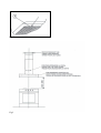
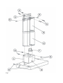
CHIMNEY HOOD
INSTALLATIONS INSTRUCTIONS
MODELS
K90CON1X
K122CONX
Fig. 1
Fig.2
Fig.3
Fig.4
Fig.5
Introduction
PLEASE READ ALL INSTRUCTlONS CAREFULLY BEFORE COMMENCING INSTALLATlON. CHECK THAT THE
ELECTRICAL SUPPLY DATA QUOTED ON THE RATlNG PLATE OF THE APPLIANCE AGREES WITH THAT OF
YOUR SUPPL Y. (SEE NOTE "SAFETY REQUIREMENTS")
These instructions are designed to tell you of the various technical details of your cooker hood and to make you familiar
with its use. Since these instructions cover more than one type of the hood within the same series, it may be that
reference is made to components that do not form part of the hood that you are installing. The hood may be used an
exhaust hood.
Suggestions for using the hood in exhaust position
When an exhaust hood and a heat source requiring ambient air (e.g. gas, oil, coal stoves, etc.) are used at the same
time, attention is required because the air necessary for combustion is exhausted from the room through the hood and,
this creates depression. There is no such danger when the maximum depression in the room is 0,04mbar. In this
condition no exhaust gas from the heat source is piped. There shall be adequate ventilation of the room when the range
hood is used at the same time as appliances burning gas or other fuels. To assure this condition, make openings in the
room which cannot be closed (doors, windows, etc. are not sufficient) and through which the air necessary for
combustion can freely flow.
Note: All the exhaust duct work in the apartment or house should be studied. In case of doubts, get advise or
authorization from the person or agents responsible for the building. When using gas burners, gas ovens, etc. as well as
when using the hood in the filter version, these precautions are not necessary.
Note: The efficiency of the exhaust hood decreases as the length of the ducts and number of elbows inerease. When
using the exhaust version, follow these rules: Do not connect the exhaust hood to chimney, flues, and air ducts serving
the room. Before venting into exhaust flues and ducts no longer in use, ask for the approval of the person or agency
responsible for the building. The evacuated air must not be let into a warm air duct. For the evacuation of the exhausted
air please note ufficial instructions.
Installatlon
The hood must be mounted over the centre of the cooking area. The minimum distances between the cooking area and
the underpart of the hood are 650 mm.
Warning: If the room contains a flued fuel burning appliance which is not of the "balance flue" type make sure these is
an adequate air inlet to the room at all times so that fumes are not drawn down the flue. The air must not be discharged
into a flue that is used for exhausting fumes from appliances burning gas or other fuels.
N.B. The distances, however, are subject to the safety rules in effect in the various countries. Before drilling the wall
make sure that no pipes or cables will be damages.
If there is no outer waste-pipe for the exhaust version, an air outlet with a diameter of Ø160mm, in case you use the
spigot reduction (pict.5/F) you need an exhaust outlet
Attention: Take attention that the wall will support the weight of the cooker hood (about 30 Kg). The serews supplied
with this rangehood are designed for fixing to reinforced concrete, masonry walls or hollow building blocks.
Wall fixing of the cooker hood
1) Set the dislance between the cooker hob and the hood (Pict.2-3-4 ).
2) If your hood is fitted with a metal filter frame the mounting operation can be made more easily by removing it (Pict. 1)
before beginning to work. The frame must be remounted when the operation is finished.
3) Drill the holes into the wall (Pict.5/N) at the right distance showen here after, and fix the cookerhood.
4) For a correct installation the hood is provided (in the rear side of its body) with one or two holes 8 mm diam. into which
one or two wall fixing screws mustI be inserted (Pict.5/O).
5) For the exhaust version, please connect the flange to an outlet ducting of 125 mm diameter (Pict 5/F)
- Insure that all parts are properly fixed and that it is impossible to touch moving parts.
Warning: Failure to install the screws or fixing device in accordance with these instructions may result in electrical
hazards.
Warning: DO NOT penetrate any screws into the range hood as this may result in electrical hazards.
N.B.: When using a 150 mm air outlet, do not fasten the air outlet pipe with the screws, as this might cause the metal
valve to malfunction.
Installation ofthe pipes
1) Fix the bracket (Pict.5/C) with 2 plugs and screws (Pict.5/A) in the required hight for the pipe.
2) Screw the short pipe (Pict.5/D) with 2 screws on the braeket (Pict.5/B).
3) Insert the 2 nuts in the holes on the lower part of the long pipe. Put the long pipe over the short one (Pict.5/E) by
pulling a part the laterals of the pipe.
4) Fix the long pipe wilh 2 serews on the hood (Pict. 5/Q).
Electrlc connectlon
Make sure the supply voltage ratings correspond with those stated on the appliance data plate
Attention: if the appliance is not provided with a plug or cannot be easily connected to a wall socket, then the electrical
circuit must incorporate a circuit breaker having at least a 3 mm separation between contacts. If the appliance is provided
wlth a supply cord and plug, the appliances must be positioned so that the plug is accessible.
Attentlon: the electrical supply cable must be connected as follow:
Green/Yellow=ground
Blue = neutral
Brown = line
Important: the hood manufacturer wllI not be responsible for any damage or loss caused by failure to observe these
instructions.
Important: If the supply cord is damaged, it must be replaced by the manufacturer, its service agent or similarly
qualified persons in order to avoid a hazard.
Operating instructions
The cooker hood should be switched on either before or at the same as cooking or frying commences. The grease and
carbon filters are more effective if the fan is not switched off immediately after cooking or frying is completed, but only
after a period of some 20-30 minutes. Before using the cooker hood please ensure that all plastic films like on metal
grease filter an stainless steel ducting are removed.
User instructions
Working instruction of the cooker hood
User Instructions
The cooker hood is equipped of the following functions:
the symbol
shows the ignition key for the oven light (ON / OFF)
the symbol
shows the key switch ON/OFF of the motor aspirant
shows the keys of the speeds of the motor. They increase and they decrease the
speed of the motor (there are 4 levels of possible speeds)
the symbols
the symbols
shows the key timer: the timer will run if the timer is pushed and will switch off the cooker
hood after 15 minutes.
Lamp Replacement
When the tubolar neon lamps need to be replaced this must only be done by a competent electrician because especiale
tool is required. To changes low energy neon lamps and incandescent bulbs please work from outside of the hood
means to pull off the lamp diffuser. If it has a halogen lamp look out not to touch it with your hands when you replace it.
Use a dry and not greasy protection (for example a cloth) in order to avoid a direct contact with skin which could make
the lamp break. Never use lamps with a wattage higher than the one shown on the label inside the hood.
Safety rules
Do not do any flambe cooking underneath the hood. When frying, never leave the pan alone because the cooking oil
could flare up.
CAUTION: Accessible parts may become hot when used with cooking appliances. Clean all the surfaces frequently to
avoid danger of fire. This can be done with a cloth or/and with a brush drenched with denatured alcohol or with any other
similar substances, except for the button area (pict. 5) and lamp diffuser. It is also important to remove and clean or
substitute frequently the filter installed in the hood. This appliance is not intended for use by people (including children)
with reduced physical, sensory or mental capabilities, or lack of experience and knowledge, unless they have been given
supervision and instruction concerning the use of the appliance by a person responsible for their safety.
Children should be supervised to ensure that they do not play with the appliance.
Maintenance
NOTE: Prior to any maintenance, switch off and disconnect from electrical supply.
1) Under normal cooking conditions the grease filter should be cleaned every 10-15 days in hot water, to which a suitable
detergent has been added. For reasons of efficiency and safety regular cleaning is advised. The grease filter may be
subject to a small amount of shrinkage initially.
2) The outer casing of the Cooker Hood should be cleaned with a damp cloth.
3) Once a year, (more frequently with heavy usage), cali a serviceman to clean the fan and air ducts to prevent build-up
of flammable fat deposits.
Warning: There is a fire risk if cleaning is not carried out in accordance with the instructions.
Grease fllter
This absorbs vapor-suspended grease particles and protects the kitchen and furniyure from greasy residues. The filter
should be washed every 10 to 15 days (in normaI operating conditions). Dip the filter into a de-greaser solution or put it
in the dish washer.
Make sure not to damage the filter, which is made of several layers ofthin alloy, by hitting or crushing it. The aluminium
filter will may change colour, that will have no influence of the efficiency of the filter, may it will improve it.
Replacing or cleaning the filters
To remove the aluminuim grease filter (pict.1). grab the opening tongue at the filter, pull it in your direction and move the
filter downwards. To reinstall it operate reversed.
Safety Requirements
Exhaust air must not be discharged into any chimney, or flue which may carry combustion products from other sources.
In addition, exhaust air must not be discharged into a wall cavity unless designed for the purpose. Note instructions for
cleaning fan as note «4» on «MAINTENANCE». Moreover it is important to clean regularly each filter of the hood or
replace it. N.B. THE RANGEHOOD IS DESIGNED FOR INDOOR USE ONLY. UNDER NO CIRCUMSTANCES
SHOULD THIS UNIT BE INSTALLED IN OUTDOOR CONDITION OR OVER A BARBECUE.
TECHNICAL SERVICE AND SPARE PARTS
Before leaving the factory, this appliance was tested and adjusted by specialist skilled staff to give the best operating
results. Any subsequent necessary repairs or adjustments must be carried out with the greatest care and attention by
authorised personnel. For this reason, we strongly advise you contact the Bertazzoni Service Center, specifying the
nature of the problem, the model of the equipment and the serial number. This data is provided on the data label adhered
to the base of the appliance and on the duplicate data label. Always use original Bertazzoni spare parts.
BERTAZZONI GROUP ABN 38 069 686 326
650 Bridge Road, Richmond, Victoria 3121
Service & Spare Parts: 1300 748 308
Bertazzoni After Sales Service - P.O. Box 543 SOMERTON VIC 3061
Email: [email protected]
310803