1
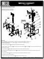
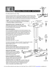
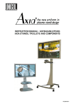
MEDIA CABINET
AVR - ASD
INSTALLATION INSTRUCTIONS
There are 3 models of cabinet only; AVR5, AVR7, AVR9.
3
There are 3 models of cabinet with mast; ASD5, ASD7, ASD9.
All series 5 and 7 have flat sides. All Series 9 have oval sides.
All have rack mounting and there are two sizes of optional shelf.
PARTS LIST
7
8
PARTS LIST
ITEM NO.
DESCRIPTION
1
2
8
SCREEN MOUNT
1500MM COLUMN
9
SIDE PANEL
BASE
10
TOP PANEL
3
COLUMN ADAPTOR
11
REAR PANEL
4
COLUMN BLANK PLATE
12
CASTOR
5
COLUMN STOPPERS
13
500mm(W) x 700mm(D) OPTIONAL SHELF
6
DOOR
14
500mm(W) x 500mm(D) OPTIONAL SHELF
7
MAST INSERT SET
15
OVAL SIDE PANEL PLUS OUTER
1
Examples:
ASD7 Shown
AVR5
500(W) X 700(H) X 500(D)
8
AVR7
M8 Screws
500(W) X 700(H) X 700(D)
AVR9
500(W) X 700(H) X 500(D)
15
9
13
ASD5
ASD7
11
ASD9
Inspect the unit before installing
Warning: Watch for pinch points. Do not put your fingers
between moveable parts. Do not tamper with or dis-assemble
any spring loaded items.
6
1. Carefully inspect the unit for shipping damage. If any damages
apparent, call your carrier claims agent and do not continue with the
installation until the carrier has reviewed the damage.
9
5
2. Lay out components to ensure you have all the required parts before
proceeding (see parts list).
2
12
Caution: To prevent damage to the unit, study all instructions and illustrations before you begin the installation.
Failure to do so could render the warranty for the unit and the equipment that attaches to it null and void.
Pay particular attention to the “warnings” displayed in these instructions.
Pay attention to the maximum weight that this unit will support. 60kg.
We recommend installation by a qualified tradesperson. If you have any questions about the installation,
contact Unicol, (uk +44 (0) 1865 767676) (europe +49 (0) 9131 9405 8013).
DRAWN BY: Andrew Griffiths
DRAWN BY DATE: 06 December 2013
REVISION:
A-001
DRAWING NO.
Ass--20018188
SHEET 1 OF 2
SHEET NAME: OVERVIEW
MEDIA CABINET
AVR - ASD
INSTALLATION INSTRUCTIONS
3
Assembly of all units is the same.
AVR9 and ASD9 have oval sides.
ASD7
7
8
1
ASD9
8
15
M8 Screws
4
9
13
14
11
6
9
15
2
12
5
Assembly:
Identify Base 2 . If you have the AVR5, 7 or 9 do not fit Column Stoppers 5 . For ASD5, 7 or 9
using columns, locate the 2 Column Stoppers 5 in the receptacles in the base to prevent
the columns hitting the floor.
1. and 2. Fix the side panels 9 to the base using the M8 screws provided.
3. and 4. Locate the rod on the door 6 in the hole in the corner of the base 2 and Top 8 . Fix the Top to the Side Panels using
the M8 screws provided.
5. Fix the Rear Panel 11 to the Base, Side Panels and Top using the M8 screws provided.
6. If columns are being used place the columns 1 through the Top and locate them into the holes in the Base, (resting on the
column stoppers).
7. Place column adaptor 3 down the columns at the desired height and tighten grub screws.
8. See separate Instructions to fit Screen.
9. Cable up unit then press in mast inserts 7 between columns (cut-outs to rear).
DRAWN BY: Andrew Griffiths
DRAWN BY DATE: 06 December 2013
REVISION:
A-001
DRAWING NO.
Ass--20018188
SHEET 2 OF 2
SHEET NAME: INSTRUCTIONS