1
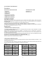
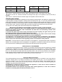
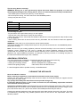
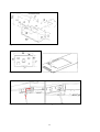
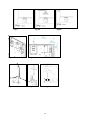
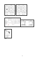
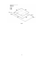
INSTRUCTIONS FOR THE INSTALLATION, MAINTENANCE AND USE OF FIXED HOBS WITH GAS OR MIXED SUPPLY DIMENSIONS: (605 mm)(W) x (520 mm)(D) (TYPE PM6V) ‘A’ Models PM6030X Models PM6040X (TYPE PM6V) ‘B’ 310733 Read this instruction booklet before installing and using the appliance. The manufacturer will not be responsible for any damage to property or to persons caused by incorrect installation or improper use of the appliance. The manufacturer reserves the right to make changes to its products when considered necessary and useful, without affecting the essential safety and operating characteristics. This appliance has been designed for non-professional, domestic use only. THIS APPLIANCE HAS BEEN DESIGNED FOR NON PROFESSIONAL USE IN HOUSEHOLDS. By ensuring this product is disposed of correctly, you will help prevent potential negative consequences for the environment and human health, which could otherwise be caused by inappropriate waste handling of this product. The symbol on the product indicates that this product may not be treated as household waste. Instead it shall be handed over to the applicable collection point for the recycling of electrical and electronic equipment. Disposal must be carried out in accordance with local environmental regulations for waste disposal. For more detailed information about treatment, recovery and recycling of this product, please contact your local city council office. This appliances is not indended to be used by people (children included) with reduced psychic and motor capacities, or with lack of experience and knowledge, unless there is supervision or instruction on the use of the appliance by a person responsible for their safety ‘’ Children must be supervised to make sure that they do not play with the appliance’’ TECHNICAL MANUAL FOR THE INSTALLER INFORMATION FOR THE INSTALLER The installation, all regulations, changes and maintenance referred to in this part must only be carried out by qualified staff. A wrong installation can cause damage to persons, animals or things which the manufacturer cannot be held responsible for. The safety and automatic regulation devices on the appliances can only ever be changed by the manufacturer or by the supplier which has been authorised to do so. INFORMATION FOR THE INSTALLER The installation, all regulations, changes and maintenance referred to in this part must only be carried out by qualified staff. A wrong installation can cause damage to persons, animals or things which the manufacturer cannot be held responsible for. The safety and automatic regulation devices on the appliances can only ever be changed by the manufacturer or by the supplier which has been authorised to do so. This appliance shall be installed only by authorised persons and in accordance with the manufacturer's installation instructions, local gas fitting regulations, municipal building codes, electrical wiring regulations, local water supply regulations, AS/NZS 5601.1-2010-Gas Installations– General installations and any other statutory regulations. This appliance is not intended to be operated by means of an external timer or separate remotecontrol system. NOT FOR USE IN MARINE CRAFT, CARAVANS OR MOBILE HOMES UNLESS EACH BURNER IS FITTED WITH FLAME SAFEGUARD. WHERE THIS APPLIANCE IS INSTALLED IN MARINE CRAFT OR IN CARAVANS, IT SHALL NOT BE USED AS A SPACE HEATER. WARNING: SERVICING SHOULD BE CARRIED OUT ONLY BY AUTHORISED PERSONNEL. 2 DO NOT MODIFY THIS APPLIANCE. Descriptions DESCRIPTIVE CAPTION FOR HOB DESCRIPTION OF HOBS 1. Dual burner 2. Rapid burner 3. Medium burner 4. Small Burner 5. Dual in burner control knob 6. Dual out burner control knob 7. Rapid burner control knob 8. Medium burner control knob 9. Small burner control knob Model ‘A’ Fig. 11 Model ‘B’ Fig. 12 Inserting the hotplate After having removed the various loose parts from the internal and external packing, make sure that the hotplate in not damaged and is suitable for the specific gas usage. The gas type label is on the underside of the hotplate base. In case of doubt, do not use the appliance and contact skilled personnel. Keep all the packing parts (polystyrene foam, cardboard, staples, etc.) away from children. Consider the critical dimensions of the appliance, before making an opening in the top surface of the bench top. (relative measurements as per Fig 1, 2 & 16). Requirements 1. Overhead clearances (Minimum values) The minimum overhead clearances shall be in accordance with the minimum values indicated in the table n.1 and are shown and in the fig. 1- 2 Range hoods and exhaust fans shall be installed in accordance with the manufacturer’s instructions. However, in no case shall the clearance between the top of the highest burner of the cooking appliance and the range hood be less than 650mm. Any other downward facing combustible surface less than 600mm above the top of the highest burner shall be protected for the full width and depth of the cooking surface area. However, in no case shall this clearance to any surface be less than 450mm. Maximum depth for the overheads cabinet is 330mm 2. Side clearances (Minimum values) The different side clearances shall be in accordance with the minimum values indicated in the table n.1 and are shown and in the fig. 1- 2 The cooking surface area is defined as that part of the appliance where cooking normally takes place and does not include those parts of the appliance containing control knobs. Table n.1 Type A - B Hobs models Type A - B (mm) Min. Clearances (mm) L1 500 L10 560 L2 40 L11 915 L3 70 W 605 L4 457 D 520 L5 610 B1 (*) 60 L6 330 B2 (*) 152 Hobs models Min. Clearances 3 L7 925 B3 (*) 60 L8 40 B4 (*) 152 L9 172 (*) Note: -B1 is the min. clearance between the front edge of the appliance and the front edge of the cabinet. -B2 and B4 are the min. clearance between the left/right side edge of the appliance and the side wall (if present). -B3 is the min. clearance between the back edge of the appliance and the back wall. Attaching the hotplate To prevent liquids from leaking accidentally into the underlying storage space, the appliance is equipped with a special gasket. To apply this gasket, carefully follow the instructions in Fig. 3. Lay out the protective sealing strips along the edges of the opening in the bench top and carefully overlap the strip end. (See Fig. 3). insert the hotplate into the bench top opening. With a screwdriver assemble the brackets to the hotplate bottom by means of the screws . (See Fig. 3A-3B). Slide the hooks into position and secure them with the screws. Trim the part of the sealing strips which extend beyond the hotplate base IMPORTANT INFORMATION CONCERNING THE INSTALLATION OF THE APPLIANCE The hob can be installed by itself, in an isolated position or inserted between two kitchen units or between one kitchen unit and a wall. Furthermore the back wall and surrounding surfaces must resist a temperature of 65 K. To prevent the plastic layer which covers the kitchen unit from ungluing, the glue used to join the two surfaces together must resist temperatures of up to 150 °C The installation of the appliance must be carried out according to the norms in force of the country concerned and the appliance must be installed in a well ventilated place. This appliance is not equipped with devices to remove the products of combustion. The appliance must therefore be connected following the norms for installation mentioned above. Special attention must be paid to the information below regarding aeration and ventilation of the premises. Data Label - The Data Label is located on the bottom of the appliance. A duplicate Data Label is supplied to adhere in an accessible area next to the appliance. This appliance is suitable for Natural Gas and Universal LPG; ensure that the available gas supply matches the Data Label and the gas type label. VENTILATION OF THE PREMISES To guarantee that the appliance works correctly it is necessary that the place where the appliance is installed is continuously ventilated. The volume of the premises must not be less than 25 m³ and the quantity of air needed must be based on the regular combustion of gas and on the ventilation of the premises. The natural flow of air will take place through permanent openings made in the wall of the premises to be ventilated: these openings will be connected to the outside and must have a minimum section of 100 cm² ( see Fig. 4 ). These openings must be made in such a way that they cannot be obstructed. POSITION AND VENTILATION The cooking appliances that use gas must always remove the products of combustion via a hood linked to chimneys, chimney flues or via a direct connection to the outside ( see Fig. 5A ). If it is not possible to fit a hood it is possible to use a fan, fitted on the window or facing directly outside, which operates when the appliance is in use. ( see Fig. 5B ). In this way the norms in force of the country concerned regarding the ventilation of premises are strictly followed. ATTENTION: An exhaust fan may be used with the appliance; in each case it shall be installed in conformity with the national standards in force. ATTENTION: Exhaust hood operation may affect other vented appliances; in each case it shall be installed in conformity with the national standards in force. 4 CONNECTING THE APPLIANCE TO THE GAS SUPPLY Before connecting the appliance to the gas supply you first need to remove the plastic protective plug for the gas supply which is inserted under pressure in the gas inlet connection. To remove the plug simply unscrew it. Then make sure that the details shown on the label on the lower part of the case are compatible with those of the gas supply. A label on the last page of this manual and on the lower part of the case indicates the conditions for regulating the appliance: type of gas and pressure used. IMPORTANT: This appliance must be installed in accordance with the norms in force of the country concerned and it must only be used in a well-ventilated place. ATTENTION: Remember that the gas inlet connection for the appliance is threaded 1/2 gas cylindrical male in accordance with the norms UNI-ISO 228-1. (Fig. 6-7) There are two ways to make the connection to the main gas line: A. The hotplate can be connected with rigid pipe as specified in AS5601 table 3.1. B. The hotplate can be connected with a Flexible Hose, which complies with AS/NZS 1869 (AGA Approved), 10mm ID, class B or D, no more than 1.2m long and in accordance with AS5601. WARNING: Ensure that the hose assembly is restrained from accidental contact with the flue or flue outlet of an underbench oven and it does not contact the hot surfaces of the hotplate, oven, dishwasher or other separate appliance that may be installed underneath or next to the hotplate. The hose should not be subjected to abrasion, kinking or permanent deformation and should be able to be inspected along its entire length. Unions compatible with the hose fittings must be used and connections tested for gas leaks. The supply connection point must be accessible with the appliance installed. Fit the supplied elbow and gasket as shown in Fig.15 The gas inlet connection has a 1/2" BSP male thread. When making the connection, take care not to apply excessive stress by counterbalancing tightening force. Ensure that the available gas supply is the same as the gas type label affixed to the base of the hob. If not, contact Technika for a Gas Conversion Kit. The gas supply pressure must be adjusted in accordance with the data label for the gas type. Natural Gas The natural gas regulator supplied must be fitted for natural gas. Ensure the arrow on the regulator points towards the direction of the gas flow. The test point pressure must be adjusted to 1.00 kPa with the largest burner operating on maximum flame. Propane Gas Fit the LPG test point assembly (supplied in the gas conversion kit). An AGA Approved gas regulator suitable for a supply pressure of 2.75kPa should be part of the gas tank supply. CHANGING THE NOZZLES FOR USE WITH OTHER TYPES OF GAS: To change the nozzles of the burners use the following procedure: Lift up the burners and unscrew the nozzles ( Fig. 9) using an adjustable spanner of 7 mm and change the nozzles with those designed for the new gas supply according to the information given in TABLE A shown below. TABLE N°2: Adaption to various types of gas Burner Types of Gas Semi-Rapid NG Propane Rapid NG Propane Dual NG Inner Propane Dual NG Outer Propane Pressure kPa 1.0 2.75 1.0 2.75 1.0 2.75 1.0 2.75 Nozzle Diameter mm. 1,17 0,73 1,50 0,92 0,80 0,50 2x1,14 2x0,73 Hourly Gas Consumption (MJ) 6,6 6,9 11.0 10.8 3.1 3.1 12.5 13.9 5 CAUTION: save the orifices removed from the appliance for future use Regulation of burners Regulation of the "MINIMUM" on the burners To regulate the minimum on the burners carry out the following procedure indicated below: 1) Turn on the burner and put the knob onto position MINIMUM ( small flame ). 2) Remove the knob ( Fig. 10) of the tap which is set for standard pressure. The knob is found on the bar of the tap itself. 3) Beside the tap bar on the work top, use a small screwdriver that fits the screw (gold) found on the lower part of the tap and turn the fixing screw to the right or left until the flame of the burner is regulated in the most suitable way to MINIMUM. 4) Make sure that that the flame does not go out when changing the position quickly from MAXIMUM to the MINIMUM position. ATTENTION: The regulation described above can be carried out only with burners using natural gas, while with burners using propane gas the screw must be fully screwed in, in a clockwise direction. CONNECTION OF THE APPLIANCE TO THE ELECTRICITY SUPPLY: Connection to the electricity supply must be carried out according to the norms and indications of the law in force. Before carrying out the connection check that: - The electric charge of the system and the sockets are suitable for the maximum power of the appliance ( see label on the lower part of the case ). - The socket or system is equipped with an efficient earth connection according to the norms and indications of the law currently in force. No responsibility can be held if these indications are not respected. When the connection to the electricity supply is made with a socket. Fit onto the electric cable a standard plug ( if it is not provided ) which is appropriate for the charge indicated on the label. Connect up the wires according to the diagram in Fig. 8 taking care to respect the corresponding pairs listed below: letter L (phase) = brown coloured wire; letter N (neutral) = blue coloured wire; symbol” ” earth = green-yellow coloured wire; - The electric cable must be positioned so that it cannot reach a temperature of over 75 K at any point. - Do not use reducers, adapters or shunts for the connection as they could cause false contacts and subsequent dangerous overheating. WARNING: The plug must be made accessible after installation for easy servicing and maintenance. WARNING: If the supply cord is damaged, it must be replaced by the manufacturer or its service agent or a similarly qualified person in order to avoid a hazard. When the connection is made directly with the electricity supply: - To connect the appliance directly to the supply mains, a means for disconnection having a contact separation in all poles that provide full disconnection under overvoltage category III conditions, must be incorporated in the fixing wiring, according with the wiring rules. - Remember that the earth wire must not be interrupted by the switch. - Alternatively the electrical connection can also be protected by a differential switch of high sensitivity. - You are strongly advised to fix the special yellow-green earth wire to an efficient earthing system Wiring diagrams For hotplate see Fig. 13. Wiring diagram description 1. Cable terminal 2. Ignition switch 3. Spark generator 4. Ignition spark 6 L. Black N. White T. Green (earth) BEFORE LEAVING When the installation is complete, always check for gas leaks using a soapy solution. Never use a flame to make this check. Ignite all burners on high flame to ensure correct operation of gas valves, burners and ignition. Turn gas taps to low flame position and observe each burner to ensure they ignite completely at all ports and that the flame is stable. Conduct these checks for each burner individually and concurrently. When satisfied with the hotplate, please instruct the user on the correct method of operation. In case the appliance fails to operate correctly after all checks have been carried out, please call the Bertazzoni Service Centre. USER INSTRUCTIONS WARNINGS: Keeping appliance area clear and free from combustible materials, gasoline and other flammable vapors and liquid. Do not store dangerous or flammable material in the cabinet areas above appliance; store them in a safe place in order to avoid potential hazards. DO NOT USE OR STORE FLAMMABLE MATERIALS NEAR THIS APPLIANCE. DO NOT SPRAY AEROSOLS IN THE VICINITY OF THIS APPLIANCE WHILE IT IS IN OPERATION. DO NOT STORE OR USE FLAMMABLE LIQUIDS OR ITEMS IN THE VICINITY OF THIS APPLIANCE. DO NOT MODIFY THIS APPLIANCE. WHERE THIS APPLIANCE IS INSTALLED IN MARINE CRAFT OR IN CARAVANS, IT SHALL NOT BE USED AS A SPACE HEATER. WARNING: SERVICING SHOULD BE CARRIED OUT ONLY BY AUTHORISED PERSONNEL. For description of hotplates refer to installation instructions. Using burners A diagram is etched on the control panel above each knob which indicates which burner corresponds to that knob. Manual ignition: Manual ignition is always possible even when the power is cut off or in the event of prolonged power failure. Turn the knob that corresponds to the burner selected counterclockwise to the MAXIMUM position at the etched star (large flame) and place a lit match up to the burner. Burners fitted with a safety device (thermocouple): Turn the knob that corresponds to the burner selected counterclockwise to the MAXIMUM position at the etched star (large flame) and then press the knob down to activate the spark ignition. Once ignited, keep pressing the knob for about 10 seconds to allow the flame to heat the thermocouple. If the burner does not remain alight after releasing the knob repeat the above procedure. If the flame does not light after the first attempt, wait 5 minutes for the gas to dissipate before attempting to re-light the burner. Note: Dual burner is composed by two burner (inside and outside); each one operates under the relative gas valve independently from the other one. Note: It is recommended not to try to ignite the burner if the relative flame cap is not in the correct position 7 Tips for using burners correctly: WARNING: During use of each gas burner(s) adjust the burner flame size properly so it does not extend beyond the edge of the cooking utensil. This is an instruction based on safety considerations - Use suitable pots for each burner (see Fig. 14 and Table B) - When the liquid is boiling, turn down the knob to the MINIMUM position. - Always use pots with a cover. Table B Burner Small Medium Large Dual Recommended pan diameters (mm) 120 – 140 140 – 260 180 – 260 220 – 260 Correct usage of pans: - Dry the bottom of the pan before placing it on the hotplate. - Use pots with a flat, thick bottom, except for wok cooking. - When using the burners, ensure that the handles of the pans are correctly positioned. Keep children away from the appliance. - When cooking foods with oil and fat, which are very flammable, the user should not leave the appliance unattended. WARNING: If the power is cut off, the burners can be lit with matches. The burners equipped with a safety thermocouple can only be lit when the knob is in the MAXIMUM position (large flame etching). Note: The use of a gas cooking appliance produces heat and humidity in the room where it is installed. Therefore, proper ventilation in the room is needed and natural ventilation openings must remain unobstructed and activating the mechanical exhaust fan/range hood. Intensive and continuous use of the appliance may require additional ventilation, for example by opening a window, or increasing the power of the mechanical exhaust fan/range hood, if installed. ABNORMAL OPERATION Any of the following are considered to be abnormal operation and may require servicing: • Yellow tipping of the burner flame. • Burners failing to remain alight. • Sooting up of cooking utensils. • Burners extinguished by cupboard doors. • Burners not igniting properly. • Gas valves, which are difficult to turn. In case the appliance fails to operate correctly, contact Bertazzoni. CLEANING THE APPLIANCE Never use abrasive cleaners Before cleaning the appliance it should be disconnected from the power supply. Cleaning the work surface: periodically clean the burner heads, the enamelled steel pan supports and the burner caps using warm water. Any spillage must always be removed as soon as possible using a rag. If it become difficult to open or close a valve, do not force it, but immediately request the assistance of the technical service personnel. Cleaning the enamelled parts: Enamelled parts should be cleaned frequently with soapy water. Never use abrasive powder. Do not leave acidic or alkaline substances on the enamelled parts (such as vinegar, lemon juice, salt, tomato sauce, etc.) and do not wash the enamelled parts while they are still hot. Cleaning the stainless steel parts: Clean the parts with soapy water and dry them with a soft cloth. The shine is maintained by periodically using suitable products which can be found in the supermarket. Never use abrasive powders. 8 Cleaning the burner caps: Lift the burner caps from the burner heads and wash them in soapy water and dry thoroughly. Before replacement on the burner head ensure that the holes are not clogged. SERVICE & MAINTENANCE INSTRUCTIONS Service and maintenance only to be carried out by an authorised person Routine maintenance Have the condition and efficiency of the gas pipe and the pressure regulator (if installed) checked periodically. If anomalies are found, do not repair components but have the faulty component replaced. To ensure good performance and safety, the gas regulator taps must be greased periodically. Periodic lubrication of the taps and any other appliance service must only be carried out by Authorised Personnel. To replace parts such as burners, valves and electric components, the hotplate must be removed from the bench top by releasing the attachment hooks, loosening the attachment screws of each burner, unscrewing the hotplate attachments nuts which are visible at the bottom of the surface, removing the hotplate top and finally replacing the defective parts. Note: if the valves must be replaced, first disassemble the ignitions switches wires. It is recommended to replace the valve gaskets each time the valve is replaced, thus ensuring a perfect seal between the body and the gas train. WARNING: Disconnect power before servicing unit. For the location of the wall receptacle for the connection of the three-pin earthed plug of the appliance, see indications given in Fig. 1- 2 WARNING: After first installation of the appliance or after any service intervention concerning main gas parts of the appliance, make the leak test using water with soap on the gas connections in order to verify the correct installation. Do not use fire for gas leak testing. CHANGING THE PARTS Before carrying out any maintenance work, disconnect the appliance from the gas and electric supply. To replace different components such as burners, taps and electrical parts you must take out the hob from the kitchen unit by releasing the fixing hooks, unscrew the fixing screws of the burners on the work top, unscrew the fixing nuts of the electric plates which are visible on the lower part of the hob and remove the worktop in order to carry out the replacement of the defective parts. NOTE: If the taps need replacing you also need to unscrew the two fixing screws of the gas ramp at the bottom of the hob which are found on the upper part of the latter. For appliances equipped with automatic “ON” switches you must dismantle the “ON” switch chain before replacing the taps. You are advised to change the seal on the tap every time you replace a tap in order to ensure a perfect hold between the body and ramp. WARNING: The power cord supplied with the appliance is connected to the appliance with a type Y connection (in compliance with standards EN 60335-1, EN 60335-2-6 and subsequent amendments) for which it must be replaced by the manufacturer or its service agent or a similarly qualified person in order to avoid a hazard. In the event of wear or damage to the mains cable, replace it with : Type/ section of mains cable H05VV-F 3x0,75 mm2 or H05RR-F 3x0,75 mm2 WARNING: If you replace the electric mains cable the installer must have the earth conductor about 2 cm longer than the phase conductors and must also take heed of the warnings regarding electric connection. 9 After-sales technical service and spare parts Before leaving the factory, this appliance was tested and adjusted by specialist skilled staff to give the best operating results. Any subsequent necessary repairs or adjustments must be carried out with the greatest care and attention by authorised personnel. For this reason, we strongly advise you contact the Bertazzoni Service Center, specifying the nature of the problem, the model of the equipment and the serial number. This data is provided on the data label adhered to the base of the appliance and on the duplicate data label. Always use original Bertazzoni spare parts. BERTAZZONI GROUP ABN 38 069 686 326 650 Bridge Road, Richmond, Victoria 3121 Service & Spare Parts: 1300 748 308 Bertazzoni After Sales Service - P.O. Box 543 SOMERTON VIC 3061 Email: [email protected] 10 Fig 1 Fig 2 Fig.3 Fig. 3A Fig. 3B 11 Fig.4 Fig.5A Fig.6 Fig.7 Fig.8 Fig.9 Fig.5B Fig.10 12 Fig.11 Fig.13 Fig.12 Fig.14 Fig.15 13 Fig.16 14