1
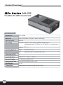
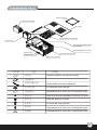
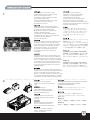
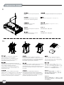
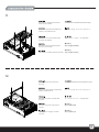
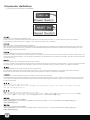
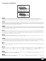
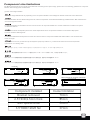
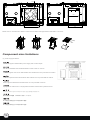
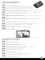
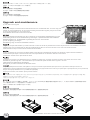
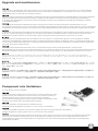
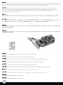
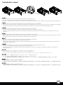
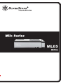
ML05
ML05
Product Overview
ML05
The Mini-ITX HTPC benchmark
Specification
Model No.
SST-ML05B
Material
Acrylic and plastic front panel, 0.8mm steel body
Motherboard
Mini-ITX
Drive Bay
Exposed 9.5mm/12.7mm slim slot-loading optical drive x 1
(replaceable with 3.5” HDD x 1 or 2.5” HDD x 2 or 120mm fan x 1)
Cooling System
1
Internal
2.5” x 4
Right
2 x 80mm fan slot
Top
120mm fan slot / oversized PSU vents
Expansion Slot
1
Front I/O Port
USB 3.0 x 2、audio x 1、MIC x 1
Power Supply
1 x Optional standard SFX
Expansion Card
1x low profile width restriction-2.95"
Net Weight
2.1 kg
Dimension
350mm (W) x 99 mm (H) x 204 mm (D), 7liter
TOP FILTER (FF143)
2.5” HDD (NOT INCLUDED)
TOP COVER
SXF PSU (SOLD SEARATELY)
MULTIPURPOSE 4+IN-1 BRACKET
2.5” HDD CAGE
LOW PROFILE EXPANSION CARD
(NOT INCLUDE)
MOTHERBOARD (NOT INCLUDE)
RESET BUTTON
POWER BUTTON
8025 FAN X2 (NOT INCLUDE)
USB 3.0 X2 + SPK + MIC
PICTURE
ITEM
MANUAL
PURPOSE
MANUAL Installation and maintenance guide
ZIPPER BAG
BUNCH WIRE TIES
BUNCH WIRE TIES Cable management
FF143-FILTER
FF143-FILTER 140mm fan filter
ZIPPER BAG
RUB-FAN Spacer for 120mm fan on multipurpose bracket
RUB-FAN
SCW-6-32 Secure motherboard, PSU and 3.5” drives
SCW-6-32
SCW-M3 Secure 2.5” drives
SCW-M3
FF143-FILTER 140mm fan filter
SCW-M2
RUB-FAN Spacer for 120mm fan on multipurpose bracket
RUBBER
RUB-FAN Spacer for 120mm fan on multipurpose bracket
2
1.
Unscrew the three screws from the
rear of the chassis then remove the
top cover.
Отвинтите три винта с задней части
корпуса, затем снимите верхнюю
крышку..
Lösen Sie die drei Schrauben von
der Rückseite des Gehäuses,
entfernen Sie dann die obere
Abdeckung.
케이스 뒷편의 3개의 나사를 풀은뒤
상부 커버를 제거합니다.
Dévissez les trois vis à l'arrière de
boîtier et ensuite retirez le panneau
supérieur.
ケースの後ろからネジ3本を外し、
それから上部カバーを取り外します。
Destornille los tres tornillos de la
parte posterior del chasis y luego
retire la cubierta superior.
先用螺絲起子鬆開三顆螺絲,再取下上蓋板.
Svitare le tre viti sul retro dello
chassis per rimuovere il cover
superiore.
先用螺丝起子松开三颗螺丝,再取下上盖板.
Unscrew two screws from the
center brace to remove it.
Отвинтите два винта с центральной
скобы, чтобы снять ее.
Lösen Sie die beiden Schrauben
von der mittleren Verstärkung,
nehmen Sie sie heraus.
중심 브레이스에서 두개의 나사를
풀어 제거합니다..
Dévissez les deux vis fixant la barre
centrale pour la retirer.
センターブレースからネジ2本を外して、
取り外します。
Destornille los dos tornillos del
soporte central para retirarlo.
鬆開中支架2顆螺絲,卸下中支架
Svitare le due viti dal sostegno
centrale per rimuoverlo.
松开中支架2颗螺丝,卸下中支架
Unscrew screws from the hard
drive bracket to remove it.
Отвинтите винты с держателя
жесткого диска, чтобы снять его.
Lösen Sie die Schrauben der
Festplattenhalterung,
entfernen Sie sie.
하드 드라이브 브라켓을 제거하기 위해
나사를 제거합니다.
Dévissez les vis du casier à disques
durs pour le retirer.
ハードドライブブラケットのネジを
外して、取り外します。
Quite los tornillos del bracket del
disco duro para retirarlo.
鬆開硬碟架螺絲,卸下硬碟架
Svitare le viti del supporto hard
drive per rimuoverlo.
松开硬盘架螺丝,卸下硬盘架
繁体中文
简体中文
2.
繁体中文
简体中文
3.
繁体中文
简体中文
3
4.
Install power supply into the case. Please note the case supports mounting power supply in two different orientations. If you use SilverStone’s SFX
power supply, you must install it with the 80mm fan facing up.
(For more information regarding power supply size limitations, please refer to the component guide in later pages)
Installieren Sie das Netzteil im Gehäuse. Bitte beachten Sie, dass das Gehäuse die Montage des Netzteils in zwei verschiedenen Ausrichtungen
unterstützt.
Wenn Sie SilverStones SFX-Netzteil verwenden, müssen Sie dieses mit dem 80-mm-Lüfter nach oben installieren.
(Weitere Informationen zur Beschränkung der Netzteilgröße entnehmen Sie bitte der Komponentenanleitung weiter hinten)
Installez l'alimentation dans le boîtier. Veuillez noter que le boîtier permet le montage des alimentations dans les deux sens.Si vous utilisez une
source d'alimentation SIlverStone SFX, vous devez l'installer avec le ventilateur de 80 mm face vers le haut.
(Pour plus d'informations sur les limitations des tailles des alimentations, veuillez-vous référer au guide des composant dans les pages à venir)
Instale la fuente de alimentación en la carcasa. Por favor, tenga en cuenta que la carcasa monta la fuentes de alimentación orientada de dos
modos distintos. Si usa la fuente de alimentación SFX de SilverStone, deberá instalarla con el ventilador de 80mm hacia arriba.
(Para más información sobre las limitaciones de tamaño de la fuente de alimentación, consulte por favor la guía de componentes en páginas
posteriores).
Installare l’alimentatore nel case. L’alimentatore può essere orientato in due modi differenti.Se si usa l’alimentatore SFX SilverStone, è necessario
installarlo con la ventola da 80 mm rivolta verso l'alto.
(per maggiori informazioni in merito alle limitazioni di misura degli alimentatori, fate riferimento a quanto esposto nelle pagine successive)
Установите источник питания в корпус. Обратите внимание, что можно установить источник питания в двух разных направлениях.При использовании
блока питания SilverStone SFX 80mm вентилятор охлаждения следует установить лицевой стороной вверх.
(для получения дополнительной информации относительно ограничений размера источников питания см. руководство к компонентам далее).
파워 서플라이를 케이스에 설치합니다. 이 케이스는 파워 서플라이를 두개의 방향을 설치 가능합니다. SilverStone의 SFX 전원 공급장치를 설치할
경우, 80mm 팬이 위를 향하도록 하여 전원 공급장치를 설치해야 합니다.
(만약 파워 서플라이의 크기 및 제한에 대한 자세한 정보를 확인하려면, 뒤에 나오는 부품 가이드를 참조 바랍니다. )
ケースに電源をインストールします。ケースは2つの異なる方向での電源設置をサポートしていることにご注意ください。SilverStone製SFX電源を
使用される場合、80mmファンを上向きに装着してください。
(電源サイズ制限の詳細については、後のページに記載のコンポーネントガイドをご参照ください。)
繁体中文
安裝電源供應器,請注意此機殼的正反裝設計, 如果使用銀欣的SFX電源,8cm風扇請朝上(關於電源供應器長度規格,請參考元件尺寸限制)
简体中文
安装电源供应器,请注意此机壳的正反装设计, 如果使用银欣的SFX电源,8cm风扇请朝上(关于电源供应器长度规格,请参考组件尺寸限制)
4
5.
Remove the multipurpose bracket.
Nehmen Sie die Mehrzweckhalterung
heraus.
Снимите многоцелевой кронштейн.
다목적 브래킷을 분리합니다.
Retirez le crochet multifonction.
多目的ブラケットを取り外します。
Retire el bracket multipropósito.
拆卸多功能磁架
Rimuovere la staffa multiuso.
拆卸多功能磁架
Insert the I/O shield included with your
motherboard, then install the
motherboard into the case.
Установите панель ввода/вывода
материнской платы, затем установите
материнскую плату в корпус.
Bringen Sie die bei Ihrem Motherboard
mitgelieferte Anschlussblende an,
installieren Sie dann das Motherboard
im Gehäuse.
메인보드와 동봉된 I/O 커버를 삽입한 후,
메인보드를 케이스에 설치합니다.
Insérez la plaque des ports E/S inclus
avec votre carte mère, puis mettez la
carte mère dans le boîtier.
マザーボードに付属のI/Oシールドを
装着してから、ケース内にマザーボー
ドを取り付けます。
Inserte el escudo de E/S incluido con
su placa base, luego instale la placa
base en la carcasa.
塞入I / O彈片,裝入主機板
Installate il pannello I/O della scheda
madre, quindi la scheda madre stessa.
塞入I/O弹片,装入主机板
繁体中文
简体中文
6.
繁体中文
简体中文
5
7.
We recommend at this point to start
thinking about routing the cables cleanly
before connecting them to the
motherboard, cables include fan cables,
power supply 24pin cable,
CPU ATX 4pin/EPS12V 8pin, front panel
connectors, front I/O connectors,
and USB 3.0 connector.
На этом шаге рекомендуется
продумать, как будут проложены
кабели до их подсоединения к
материнской плате: кабели
вентилятора, 24-контактный кабель
источника питания, 4-контактный
кабель ЦП ATX/8-контактный EPS 12 В,
разъемы на передней панели и передние
разъемы ввода/вывода.
Bereits ab diesem Schritt sollten Sie sich
Gedanken über eine saubere Kabelführung
machen, bevor Sie Anschlüsse am
Motherboard vornehmen; beachten Sie
sämtliche Kabelanschlüsse
(Lüfterkabel, 24-poliges Netzteilkabel,
CPU-Kabel (4-polig, ATX / 8-polig, EPS12V),
Anschlüsse der Frondblende,
E/A-Frontanschlüsse).
Nous vous recommandons de commencer dés
à présent à réfléchir au routage des câbles
avant de les branchez à la carte mère, câbles
incluant les câbles de ventilateurs, le câble
24 pin de l'alimentation, le connecteur de
processeur ATX 4pin/EPS12V 8pin, les
connecteurs du panneau frontal, et les
ports d'E/S.
Llegados a este punto le recomendamos que
empiece a pensar sobre enrutar los cables de
un modo limpio antes de conectarlos a la placa
base. Los cables incluyen los de los ventiladores,
el de 24 pines de la fuente de alimentación, el
de la CPU 4 pines ATX/8 pines EPS 12V, los
conectores del panel frontal y los conectores
frontales de E/S.
이 시점에서 메인보드에 케이블 연결을
어떻게 해야 할지 잘 고려해 봐야 합니다.
케이블은 팬 케이블, 파워 서플라이 24핀
케이블, CPU ATX 4Pin/EPS12V 8V 핀,
전면 패널 커넥터 및 전면 I/O 커넥터
등입니다.
この時点でマザーボード、ファンケーブル、
電源24ピンケーブル、CPU ATX
4ピン/EPS12V 8ピン、フロントパネルコネ
クタ、およびフロントI/Oコネクタと接続す
る前にケーブル取り回しをすっきりさせる
ことを考慮し始めるようお勧めします。
繁体中文
我們建議你在安裝主機板之前即開始準備
整線動作。包含風扇電源線, PSU 24Pin接
線 , CPU ATX 4Pin/EPS 8Pin接線,Front
Panel Connectors與Front I/O Connectors。
简体中文
我们建议你在安装主机板之前即开始准备
整线动作。包含风扇电源线, PSU 24Pin接
线 , CPU ATX 4Pin/EPS 8Pin接线,Front
Panel Connectors与Front I/O Connectors。
A questo punto vi raccomandiamo di iniziare a
pensare a come sistemare I cavi dell’alimentatore
prima di connetterli alla scheda madre. Nello
specifico i cavi delle ventole, il connettore a 24pin,
il connettore ATX 4pin/EPS12V 8pin, I connettori
del pannello frontale e quelli I/O sempre frontali.
.
8.
Remove 2.5” drive cage and
install 2.5” hard drives into the drive
cage.
Извлеките кронштейн для 2,5-дюймовых жестких дисков.
Установите 2,5-дюймовые жесткие диски в
кронштейн для жестких дисков.
Nehmen Sie die 2,5
Zoll-Laufwerkhalterung heraus.
Bauen Sie 2,5-Zoll-Festplatten in
die Laufwerkhalterung ein.
2.5” 드라이브 케이지를 제거합니다. 2.5” 하드
드라이브를 드라이브
케이지에 설치합니다.
.
Retirez le casier des lecteurs 2.5”.
Installez les disques durs 2.5”dans
le casier.
2.5インチドライブケージを取り外します。
ドライブケージに2.5インチハードドライブを
装着します。
繁体中文
安裝2.5”硬碟到2.5”硬碟架上,安裝2.5”硬碟架
Quite la carcasa para dispositivos
de 2,5”. Instale discos duros de
2,5” en la carcasa para dispositivos.
Rimuovere il supporto hard drive
da 2,5”. Installare gli hard drive
da 2,5” nel supporto.
简体中文
安装2.5”硬盘到2.5”硬盘架上,安装2.5”硬盘架
6
9.
Install and secure required expansion
cards.
Установите и закрепите необходимые платы расширения.
Installieren und befestigen Sie die
erforderlichen Erweiterungskarten.
필요한 확장카드를 설치하고 고정시킵니다.
.
Installez et fixez les cartes
d'extension requises.
必要とされる拡張カードをインストールし、
固定します。
Instale y fije las tarjetas de expansión
necesarias.
移除介面卡檔片,安裝介面卡
Installare ed assicurare le schede
di espansione necessarie.
移除适配卡档片,安装适配卡
繁体中文
简体中文
10.
Depending on requirement, install either
slim optical drive, a 3.5” hard drive,
two 2.5” hard drive, or a 120mm fan onto
the multipurpose bracket. Remember to
install rubber padding for the fan.
Dependiendo de los requisitos, instale bien
un dispositivo óptico delgado, un disco duro de 3,5”,
dos discos duros de 2,5” ó un ventilador de 120mm
en el bracket multipropósito. Recuerde instalar la
almohadilla de goma para el ventilador.
요구사항에 따라 슬림형 광드라이브,
1개의 3.5” 하드 드라이브, 2개의 2.5”
하드 드라이브 또는 1개의 120mm 팬을
다목적 브래킷에 설치합니다. 반드시 고무
패딩을 팬에 설치하십시오.
Installieren Sie je nach Bedarf entweder ein
optisches Slim-Laufwerk, eine 3,5-Zoll-Festplatte,
zwei 2,5-Zoll Festplatten oder einen
120-mm-Lüfter in der Mehrzweckhalterung.
Vergessen Sie bei der Lüfterinstallation die
Gummipolster nicht.
In base alle necessità, installare sulla staffa multiuso
una unità ottica slim, un disco rigido da 3,5”,
2 dischi rigidi da 2,5”, oppure una ventola da 120 mm.
Ricordarsi di installare l’imbottitura di gomma per
la ventola.
必要に応じてスリム光学ドライブ、3.5”
ハードディスクドライブ1台、2.5”ハード
ディスクドライブ2台または120mmファンが
多目的ブラケットに装着可能です。ファン
にはゴムパッドの装着をお忘れなく。
Suivant les besoins, installez soit le disque
optique mince, un disque dur de 3,5”, deux disques
durs de 2,5”, ou un ventilateur de 120 mm sur le
crochet multifonction. Rappelez-vous d'installer le
coussinet en caoutchouc pour le ventilateur.
В зависимости от требований установите на
многоцелевой кронштейн тонкий оптический привод,
3,5-дюймовый жесткий диск, два 2,5-дюймовых жестких
диска или 120-мм вентилятор. Не забудьте установить
резиновые прокладки для вентилятора.
視需求,安裝薄型光碟機,3.5”硬碟 2.5”
硬碟,或是風扇到多功能磁架上,安裝風扇
請記得額外安裝橡膠墊片
繁体中文
简体中文
视需求,安装薄型光驱,3.5”硬盘 2.5”硬盘,
或是风扇到多功能磁架上,安装风扇请记得额
外安装橡胶垫片
7
11.
Reinstall the multipurpose bracket
back into the chassis.
Установите многоцелевой кронштейн в корпус.
Bauen Sie die Mehrzweckhalterung
wieder in das Gehäuse ein.
다목적 브래킷을 섀시에 도로 설치합니다.
.
Réinstallez le crochet multifonction
à l'arrière du châssis.
多目的ブラケットをケースに戻します。
Reinstale el bracket multipropósito
de nuevo en el chasis.
將多功能磁架裝回機殼
繁体中文
简体中文
Reinstallare la staffa multiuso nel telaio. 将多功能磁架装回机壳
12.
Reinstall center brace back into
the case.
Установите центральную скобу обратно в корпус.
Bringen Sie die mittlere Verstärkung
wieder im Gehäuse an.
중심 브레이스를 케이스에 재 설치합니다.
.
Réinstallez la barre centrale dans
le boîtier.
ケースにセンターブレースを戻します。
Reinstale el soporte central en la
carcasa.
將中支架裝回機殼
Reinstallare il sostegno centrale
nel case.
将中支架装回机壳
繁体中文
简体中文
8
13.
Place the top cover back onto the case and secure with three
screws to complete installation.
Platzieren Sie die obere Abdeckung auf dem Gehäuse und
befestigen Sie sie zum Abschluss der Installation mit drei
Schrauben.
Remettez le panneau supérieur sur le boîtier et fixez le
avec trois vis pour terminer l'installation.
Vuelva a poner la cubierta superior en la carcasa y
fíjela con tres tornillos para completar la instalación.
Riposizionare quindi il cover superiore ed assicurarlo allo
chassis con le tre viti rimosse in precedenza per completare
l’installazione.
Завершите установку, установив верхнюю крышку обратно на корпус
и закрепив тремя винтами.
상부 커버를 케이스에 재 장착후 3개의 나사로 고정시켜
설치를 마칩니다.
ケースに上部カバーを戻し、3つのネジ3本で固定すると、
インストールは完成です。
繁体中文
將上蓋裝回機殼,完成組裝.
简体中文
将上盖装回机壳,完成组装.
9
Connector definition
(1) Front panel connector installation
Power switch and reset switch installation guide:
Please refer to the motherboard manuals for the motherboard’s “Front Panel Connector” or “System Panel Connector” pin definition.
Power switch and reset switch have no polarity, so they can be connected in any orientation.
Ein-/Ausschalter und Rücksetztaste (Reset) installieren:
Bitte suchen Sie in der Motherboard-Dokumentation nach der Pinbelegung der Anschlüsse des Frontbedienfeldes („Front Panel Connectors“
oder „System Panel Connectors“). Ein-/Austaste und Rücksetztaste benötigen keine bestimmte Polarität, können daher beliebig (ohne auf +
und - zu achten) angeschlossen werden.
Guide d'installation des interrupteurs d'allumage et de réinitialisation :
Veuillez-vous référer au manuel de votre carte mère pour la description des broches "des connecteurs du panneau frontal" et des broches "des
connecteurs du panneau système". Les interrupteurs d'allumage et de réinitialisation ne possède pas de polarité, donc ils peuvent être branché
dans les deux sens.
Guía de instalación de los interruptores de encendido y reseteo:
Por favor, consulte en los manuales de la placa base la configuración de pines del “Conector de panel frontal” ó “Conector de panel de sistema”
de su placa base. Los interruptores de encendido y reseteo no tienen polaridad, luego se pueden conectar con cualquier orientación.
Guida all’installazione dei connettori Power Switch e Reset Switch:
Fare riferimento al manuale della scheda madre nella sezione “Connettori del pannello frontale” o “Connettori del pannello di sistema”.
Power switch e reset switch non hanno polarità, posso essere pertanto connessi con qualsiasi orientamento.
Инструкция по подключению выключателя питания и кнопки перезагрузки (reset):
Описание контактов разъемов приведены в разделах “Разъемы передней панели” или “Разъемы системной панели” руководства
пользователя материнской платы. Выключатель питания и кнопка перезагрузки не имеют полярности, поэтому их можно подключать
в любой ориентации.
파워 스위치 및 리셋 스위치 설치 가이드
메인보드 매뉴얼의 전면패널 커넥터 혹은 시스템패널 커넥터 핀을 참조하기 바랍니다. 파워 스위치와 리셋 스위치는 극성이 없어
어떤 방향으로 설치해도 무방합니다.
電源スイッチおよびリセットスイッチのインストールガイド:
マザーボードの「フロントパネルコネクタ」または「システムパネルコネクタ」のピン配列についてはマザーボードマニュアルを参照
してください。電源スイッチとリセットスイッチに極性はないので、いずれの方向でも接続できま。
Power Switch 與Reset Switch安裝說明:
請參考主機說明書的Front Panel Connectors安裝Pin Define,將Connector插上;Power Switch 與Reset Switch並無正負極性之分,
反插正插都不影響功能性。
Power Switch 与Reset Switch安装说明:
请参考主机说明书的Front Panel Connectors 安装Pin Define,将Connector插上;Power Switch与Reset Switch并无正负极性之分,
反插正插都不影响功能性。
10
Connector definition
Please refer to the motherboard :
manuals for the motherboard’s “Front Panel Connector ” or “System Panel Connector” pin definition.;
the white/black wires are negative while other colors are positive wires. The Power LED wires are separate pins for compatibility with different
motherboard pin definition so please make sure they are connected in the right polarity by referring to your motherboard manual.
Bitte suchen Sie in der Motherboard-Dokumentation nach der Pinbelegung der Anschlüsse des Frontbedienfeldes („Front Panel Connectors“ oder „
System Panel Connectors“). Die weißen/ schwarz Adern sind negativ (-), die farbigen Adern positiv (+).Die Kabel für die Betriebsanzeige-LED
sind zur Kompatibilität mit unterschiedlichsten Motherboards einzeln, nicht als kompletter Stecker ausgeführt. Achten Sie hier bitte auf die richtige
Polarität, lesen Sie in der Dokumentation Ihres Motherboards nach.
Veuillez-vous référer au manuel de votre carte mère pour la description des broches "des connecteurs du panneau frontal" et des broches "des
connecteurs du panneau système". Les câbles colorés en blanc/noir sont négatifs alors que ceux d'une autre couleur sont positifs. Les câbles de
la LED Power sont séparés afin d'être compatible avec différentes cartes mères, donc vérifiez bien qu'ils sont branchés avec la bonne polarité en
vous référant au manuel de votre carte mère
Por favor, consulte en los manuales de la placa base la configuración de pines del “Conector de panel frontal” ó “Conector de panel de sistema”
de su placa base. Los cables de color blanco/negro son negativos mientras que los de color son positivos. Los cables LED de potencia tienen
pines separados para compatibilidad con diferentes definiciones de pines de la placa base luego por favor, asegúrese de que están conectados
en la polaridad correcta consultando el manual de su placa base.
Fare riferimento al manuale della scheda madre nella sezione “Connettori del pannello frontale” o “Connettori del pannello di sistema”. I cavi di
colore bianco/nero sono il polo negativo, mentre quelli di colore diverso il positivo.
Описание контактов разъемов приведены в разделах “Разъемы передней панели” или “Разъемы системной панели” руководства
пользователя материнской платы. Белые/черный провода - отрицательной полярности, цветные провода - положительной полярности.
Провода светодиодного индикатора питания имеют отдельные контакты для совместимости с различными типами контактов материнских
плат, поэтому обратитесь к руководству пользователя материнской платы и убедитесь, что полярность соблюдена.
메인보드 매뉴얼의 전면패널 커넥터 혹은 시스템패널 커넥터 핀을 참조하기 바랍니다. 하얀/검은선의 경우 음극이며, 다른 색의 경우
양극입니다. 파워 LED 선은 분리되어 다양한 메인보드에서 동작할 수 있도록 되어 있습니다. 그러므로 메인보드 매뉴얼을 참조하여 올바를
극성을 주의해 선택하시기 바랍니다.
マザーボードの「フロントパネルコネクタ」または「システムパネルコネクタ」ピン配列についてはマザーボードマニュアルを参照してください。
白/黑色のリード線はマイナスで、色の着いたリード線がプラスです。電源LEDリード線は種々のマザーボードピン定義と互換性を持たせるため
分離されたピンとなっているので、ご使用のマザーボードマニュアルを参照して、適切な極性に接続されるようお確かめください。
請參考主機說明書的Front Panel Connectors安裝Pin Define,將Connector插上; 白/黑色線的部分為負極,彩色線的部分是正極。Power LED為
了適應各主機板的不同, 特別設計為散Pin樣式,請安心使用。
请参考说明书的Front Panel Connectors安装Pin Define,将Connector插上;白/黑色线的部份为负极,彩色线的部份为正极。Power LED为了适应
主机板的不同, 特别设计为散Pin样式,请安心使用。
11
Front I/O connector guide
Below are the front I/O connectors pin definition, please also check your motherboard manual to cross reference with motherboard’s
front I/O pin headers. SilverStone’s I/O connectors are in block type to simplify installation.
Nachstehend finden Sie die Pinbelegung der vorderen E/A-Anschlüsse; bitte gleichen Sie zudem das Handbuch Ihres Motherboards mit
den vorderen E/A-Pinzuweisungen ab. SilverStones E/A-Anschlüsse befinden sich zur Vereinfachung der Installation in Blockart.
Au dessous de la description des broches des ports d'E/S, veuillez aussi vérifier sur le manuel de votre carte mère de manière croisée
que les broches sont correctement placées. Les connecteurs d'E/S de SilverStone sont en bloc pour en simplifier leur installation.
A continuación se detallan los pines para conectores E/S frontales, compruebe también por favor el manual de su placa base para
cotejar los pines E/S frontales de la misma. Los conectores E/S de SilverStone son del tipo bloque para simplificar la instalación.
Ниже приведено описание контактов передних разъемов ввода/вывода. Обратитесь также к руководству пользователя материнской
платы за описанием передних разъемов ввода/вывода типа "пин-хедер". Разъемы ввода/вывода "SilverStone" - блочного типа, что
облегчает сборку.
Di seguito lo schema delle connessioni I/O frontali, confrontare lo schema con quanto riportato sul manuale della scheda madre per
effettuare un controllo incrociato. I connettori I/O Silverstone, per semplificare l’installazione, sono del tipo “a blocco”.
아래는 전면 I/O 커넥터의 핀 사양입니다. 메인보드 매뉴얼을 참조해, 메인보드의 전면 I/O 핀사양을 재 확인한 후 설치합니다.
SilverStone의 I/O 커넥터는 블록 타입으로 구성되어 있어 간편한 설치가 가능합니다.
以下はフロントI/Oコネクタピン配列ですが、お持ちのマザーボードのフロントI/Oピンヘッダは、マザーボードマニュアルをご参照
ください。シルバーストーンのI/Oコネクタは、インストールの容易なブロックタイプになっています。
下表為Front I/O Connectors的Pin Define,請參閱主機板說明書的各Front I/O Connectors Pin Define一一核對。
ML05的Front I/O Connectors完全採用集合Pin方式以簡化安裝。
下表为Front I/O Connectors的Pin Define,请参阅主机板说明书的各Front I/O Connectors Pin Define一一核对。
ML05的Front I/O Connectors完全采用集合Pin方式以简化安装。
USB 3.0 CONNECTOR
ID
INTA_P2_D+
INTA_P1_D+
INTA_P2_D-
INTA_P1_D-
GND
GND
INTA_P2_SSTX+
INTA_P1_SSTX+
INTA_P2_SSTX-
INTA_P1_SSTX-
GND
GND
INTA_P2_SSRX+
INTA_P1_SSRX+
INTA_P2_SSRX-
INTA_P1_SSRX-
VBUS
VBUS
HD AUDIO CONNECTOR
AUD GND
PRESENCE
SENSE1_RETURN
PIN
SENSE2_RETURN
PORTIL
PORT1R
PORT2R
SENSE_SEND
PORT2R
PIN
12
Component size limitations
The ML05 was designed to be as small as possible while maximizing interior space usage, please refer to the following guidelines for component
selection and future upgrade considerations.
(1) CPU cooler height limitation
CPU Cooler height limitation will vary depending on the component installed on the multipurpose bracket. Please refer to the table below
Die maximale Höhe des CPU-Kühlers hängt davon ab, welche Komponenten in der Mehrzweckhalterung installiert wurden. Bitte orientieren Sie
sich an der folgenden Tabelle
La limite de la hauteur du refroidisseur de CPU varie en fonction du composant installé sur le crochet multifonction. Veuillez vous reporter
au tableau ci-dessous
La limitación de altura del disipador para la CPU variará dependiendo de los componentes instalados en el bracket multipropósito.
Por favor consulte la tabla siguiente
La limitazione dell’altezza del dispersore di calore CPU varierà in base ai componenti installati sulla staffa multiuso. Fare riferimento alla
tavola che segue
Ограничение по высоте для вентилятора охлаждения процессора зависит от установленных компонентов на многоцелевом
кронштейне. См. таблицу ниже
CPU 쿨러 높이 한계는 다목적 브래킷에 설치된 구성부품에 따라 다릅니다. 아래의 표를 참조하십시오.
CPUクーラー高さ限界は多目的ブラケットに装着されたコンポーネントに依存します。下表をご参照ください。
ML05 CPU Cooler限高會根據多功能磁架的裝置不同,而有所改變。請參考下表來選購CPU Cooler
ML05 CPU Cooler限高会根据多功能磁架的装置不同,而有所改变。请参考下表来选购CPU Cooler
TOP-COVER
2.5” HDD
Cooler
Slim optical drive
55
Cooler
Motherboard
50
Cooler
Motherboard
Motherboard
Ml05only supports slim “slot-loading” optical drives
12025FAN
3.5” HDD
37
Cooler
Cooler
Motherboard
Component installed
Bracket removed
2.5”HDD,9.5mm thick
Slim optical drive
3.5”HDD/12025 fan
37
Motherboard
Cooler limitation
70mm
55mm
50mm
37mm
13
35.6
120.0
34
28
102
18.7
138.7
130
Please note 3.5” hard drive and 120mm x 25mm fan are thicker and might interfere with USB 3.0 connector.
3
1
2
Component size limitations
(2) Power supply limitations
The ML05 supports standard SFX power supply with a 100mm depth.
Der ML05 unterstützt SFX-Standardnetzteile mit einer Tiefe von 100 mm.
Le ML05 supporte une source d'alimentation SFX standard avec une profondeur de 100mm.
La ML05 acepta fuentes de alimentación SFX estándar con una profundidad de 100mm.
ML05 supporta l’alimentatore standard SFX con una profondità di 100 mm.
Корпус ML05 совместим со стандартными блоками питания SFX глубиной 100 мм.
ML05는 100mm 깊이의 표준 SFX 전원 공급장치를 지원합니다.
ML05は標準SFX電源(100㎜深)に対応しています。
ML05限定使用長度為100mm的標準SFX電源
ML05限定使用长度为100mm的标准SFX电源
14
Component size limitations
(3) Graphics card/expansion card length limitation
The ML05 can accommodate low profile expansion cards up to 7.6” long.
Standard low profile cards usually are only 6.6” long so the ML03 should fit nearly all types of low profile cards.
Das ML05 Low-Profile-Erweiterungskarten mit einer Länge von bis zu 19,3 cm aufnehmen. Standard-Low-Profile-Karten
sind üblicherweise nur 16,76 cm lang - dadurch passen nahezu alle Arten von Low-Profile-Karten in das ML05.
Le ML05 peut accueillir des carte d'extension low profile jusqu'à 7.6” de long. Les cartes low profile standard ont habituellement une longueur
de seulement 6.6” long donc le ML05 pourra accueillir tous les types de cartes low profile.
La ML05 puede acomodar tarjetas de expansión de perfil bajo de hasta 7,6” de longitud. Las tarjetas normales de perfil bajo suelen tener
solo 6,6” de longitud, luego la ML05 debería poder instalar cualquiera de estas tarjetas.
ML05 può alloggiare schede di espansione a basso profilo lunghe fino a 193mm.
Le schede low profile standard sono generalmente lunghe soltanto 167,6mm quindi, all’interno di ML05, possono essere installate quasi
tutte le schede low profile.
ML05 можно установить платы расширения малых размеров длиной до 7,6 дюймов.
Стандартные платы малого размера обычно имеют длину 6,6 дюйма, поэтому ML05 должен поддерживать практически все типы
плат малого размера.
ML05은 7.6”까지 LP 형태의 확장 카드를 지원합니다.
일반적인 LP 카드의 경우 대부분 6.6” 의 길이를 갖고 있어 ML05은 거의 대부분의 LP 카드 장착이 가능합니다.
ML05は長さ最大7.6インチのロープロファイル拡張カードを装着できます。標準のロープロファイル拡張カードは通常、
長さ6.6インチに過ぎないので、ML05にはほとんど全てのタイプのロープロファイルカードが搭載可能です。
ML05 支援最長7.6”長的Low profile介面卡。
請注意一般規範的Low profile介面卡長度只有6.6”,所以任何的Low profile介面卡應當都可以安裝
ML05 支持最长7.6”长的Low profile适配卡。
请注意一般规范的Low profile适配卡长度只有6.6”,所以任何的Low profile适配卡应当都可以安装
193
Please note 3.5” hard drive and 120mm x 25mm fan are thicker and might interfere with USB 3.0 connector.
Component size limitations
(4) Optical drive limitation
The ML05 only supports slim“slot-loading” optical drives.
Below are examples of 12.7mm and 9.5mm optical drives.
Das ML05 unterstützt nur schmale optische Laufwerke („Slot-In“).
Nachstehend finden Sie Beispiele zu optischen 12,7 mm- und 9,5 mm-Laufwerken.
Le ML05 est compatible seulement avec le les lecteur optique slim sans tiroir (mange-disque aka “slot-loading”).
Quelques exemples de lecteurs optiques de 12,7 mm et de 9,5 mm sont présentés.
La ML05 sólo acepta dispositivos ópticos delgados de carga mediante ranura.
Más abajo hay ejemplos de dispositivos ópticos de 12,7mm y 9,5mm.
ML05 supporta soltanto drive ottici slim “slot-loading”.
Di seguito vengono illustrati esempi di unità ottiche da 12,7 mm e 9,5 mm.
Корпус ML05 допускает только установку тонких оптических приводов со «щелевой загрузкой».
Ниже приведены примеры оптических приводов толщиной 12,7 мм и 9,5 мм.
ML05은 슬립 슬롯 방식의 광드라이브만 지원합니다.
아래의 예는 12.7 mm 및 9.5 mm 광학 드라이브의 예입니다.
15
ML05はスリムタイプ「スロットローディング」光学ドライブのみをサポートします。
下図は、12.7mmと9.5mmの光学ドライブの例です。
ML05 只能使用吸入式薄型光碟機。
以下是12.7mm與9.5mm的光碟機範例供您做參考。
ML05 只能使用吸入式薄型光驱。
以下是12.7mm与9.5mm的光驱范例供您做参考。
Upgrade and maintenance
(1) Fan filter removal guide
Picture: An example of a PSU that has malfunctioned due to it overfilled with dust. To ensure long and
optimal use of the installed PSU, we recommend cleaning the PSU filters regularly every three months
or half a year (depending on your environment).
The illustration shows how to remove the PSU filter.
Abbildung: Beispiel eines Netzteils, bei dem es aufgrund von übermäßiger Staubablagerung zu einer
Fehlfunktion gekommen ist.Zur Gewährleistung eines langen, optimalen Einsatzes des installierten
Netzteils empfehlen wir, die Netzteilfilter regelmäßig alle drei bzw. sechs Monate
(je nach Umgebung) zu reinigen.
Die Abbildung zeigt, wie Sie den Netzteilfilter entfernen.
Image : un exemple d'alimentation qui a mal fonctionné à cause de l’excès de poussière.Pour assurer la pérennité de votre installation de manière
optimale nous vous recommandons de nettoyer régulièrement les filtres, à savoir tous les trois ou six mois selon l’environnement.
Cette illustration indique comment retirer les filtres de l'alimentation.
Imagen: Un ejemplo de una FA que ha fallado debido a estar llena de suciedad.Para asegurar una vida larga y óptima de la FA instalada, le
recomendamos que limpie a menudo los filtros de la FA, dependiendo de su ubicación cada tres ó seis meses.
La ilustración muestra cómo quitar el filtro de la FA.
Immagine: Un esempio di un alimentatore che si è guastato a seguito di un eccessivo accumulo di polvere. Per essere sicuri che il vostro
alimentatore godrà di lunga vita, vi raccomandiamo di provvedere alla pulizia dei filtri almeno ogni tre o sei mesi
(dipendentemente dalla tipologia di ambiente).
Di seguito la procedura di rimozione dei filtri delle ventole.
Рисунок: пример блока питания, неисправность которого вызвана загрязнением фильтров пылью. Для обеспечения длительного и
эффективного использования блока питания рекомендуется регулярно выполнять очистку его фильтров с периодичностью раз в три месяца
или раз полгода (в зависимости от условий эксплуатации).
На рисунке показано, как снимать фильтр блока питания.
그림 : 먼지로 가득차 오동작을 하고 잇는 PSU의 예. 장착된 PSU을 장기간 최적화되게 사용하려면, PSU 사용환경에 따라 필터를 매 3개월 혹은
6개월마다 정기적으로 청소해주기 바랍니다.
그림은 PSU 필터를 제거 하는 방법이 나타나 있습니다.
図: ホコリが一杯になり故障したPSUの例。インストールされたPSUが長く最適の使用状態を保てるよう、3ヶ月または半年(ご使用の環境に依存)
ごとに規則的にPSUフィルタを清掃するようお勧めします。
PSUフィルタの取り外し方は図に示されています。
圖:被灰塵卡死的電源供應器
視環境而定,我們建議您每3個月~半年必須清理電源濾網,以下是濾網的拆卸步驟。
图:被灰尘卡死的电源供应器
视环境而定,我们建议您每3个月~半年必须清理电源滤网,以下是滤网的拆卸步骤。
The illustration shows how to remove the PSU filter.
16
Upgrade and maintenance
The ML05 has an oversized CPU venting area on the top cover to ensure great cooling performance over the CPU area. If you require additional
cooling, we recommend installing two low speed 80mm fans such as SilverStone’s SUSCOOL81 to the right side of the case. You can purchase
additional FF81 filter to prevent dust from entering the chassis.
Das ML05 verfügt zur Optimierung der Kühlleistung oberhalb der CPU über eine überdimensionierte CPU-Belüftungsfläche an der oberen Abdeckung.
Wenn Sie die Kühlung noch weiter optimieren möchten, empfehlen wir die Installation von zwei 80 mm-Lüftern mit geringer Geschwindigkeit
(z. B. SilverStones SUSCOOL81) auf der rechten Seite des Gehäuses. Sie können einen zusätzlichen FF81-Filter gegen Eindringen von Staub
in das Gehäuse erwerben.
Le ML05 possède des aération surdimensionnées pour le processeur pour assurer une bonne performance de refroidissement. S’il vous
est nécessaire de refroidir plus nous vous recommandons d’installer 2 petits ventilateurs de faible vitesse de rotation de 80 mm comme le SUSCOOL81
de Silverstone sur le coté droit du boitier. Vous pouvez acheter un filtre supplémentaire FF81 pour éviter que la poussière ne pénètre dans le châssis.
La ML05 tiene una amplia zona de ventilación para la CPU en la cubierta superior para asegurar un alto rendimiento de la refrigeración sobre la zona
de la CPU. Si precisa de refrigeración adicional, le recomendamos que instale dos ventiladores de 80mm de baja velocidad como el Silverstone
SUSCOOL81 en el lado derecho de la carcasa. Puede comprar un filtro adicional FF81 para evitar que el polvo entre en el chasis.
ML05 possiede una sovradimensionata area di ventilazione sul cover superiore, in corrispondenza della CPU, al fine di garantire le massime
performance di raffreddamento. Qualora aveste bisogno di migliorare ulteriormente il sistema di ventilazione interno, vi consigliamo di installare due
ventole a bassa velocità nelle predisposizioni. Ad esempio potreste utilizzare quattro SilverStone SUSCOOL81. È possibile acquistare altri filtri FF81
per evitare che la polvere penetri nel telaio
На верхней крышке ML05 имеется большой участок для вентиляции ЦП для обеспечения эффективного охлаждения ЦП.
При необходимости дополнительного охлаждения рекомендуется установить в правую часть корпуса два вентилятора 80 мм малой скорости,
например SUSCOOL81 SilverStone. Вы можете дополнительно приобрести фильтр FF81 для предотвращения попадания пыли в корпус.
ML05은 오버사이즈 CPU 통기구가 상부에 있어 우수한 냉각 CPU주변에 우수한 냉각 성능을 보장합니다. 만약 추가로 냉각이 필요하다면,
SilverStone의 SUSCOOL81 과 같은 80mm 팬을 2개 까지 케이스 오른편에 추가 장착 가능합니다. 먼지가 섀시로 들어오지 못하도록 하는 FF81
필터를 추가로 구매할 수 있습니다.
ML05は、CPUエリア上方の大きな冷却性能を確保するため、上部カバーに特大のCPU換気口を有しています。さらなる冷却が必要であれば、ケース右
側にSilverstone製SUSCOOL81などの低速度80mmファン2台をインストールするようお勧めします。ホコリがケースに侵入するのを防ぐには、FF81フィ
ルターを別途ご購入いただけます。
SilverStone已經在CPU上方有開專用進風孔,以確保系統在任何配置下都能達到優良的散熱效能。如果您還想要增加CPU區塊的散熱效能,我們建議您可
以選購2顆SilverStone SUSCOOL 81,並安置在機殼右方。必要的時候可以額外選購FF81濾網。
SilverStone已经在CPU上方有开专用进风孔,以确保系统在任何配置下都能达到优良的散热效能。如果您还想要增加CPU区块的散热效能,我们建议您可
以选购2颗SilverStone SUSCOOL 81,并安置在机壳右方。必要的时候可以额外选购FF81滤网。
Component size limitations
(3) VGA (D-sub) connector installation
Located near the first expansion slot of the case, there is a cutout in the shape of a VGA
(D-sub) connector, this is designed to help save the use of an expansion slot that may
otherwise be taken up by the connector in a two slot low profile configuration.
We recommend selecting a graphics card with single low profile slot configuration to take
advantage of the VGA (D-sub) cutout implemented in the ML05.
Das ML05 unterstützt nur schmale optische Laufwerke („Slot-In“).
Nachstehend finden Sie Beispiele zu optischen 12,7 mm- und 9,5 mm-Laufwerken.
Le ML05 est compatible seulement avec le les lecteur optique slim sans tiroir (mange-disque aka “slot-loading”).
Quelques exemples de lecteurs optiques de 12,7 mm et de 9,5 mm sont présentés.
Localizado cerca del primer zócalo de expansión de la carcasa, existe un agujero en forma de conector VGA (D-sub) diseñado para ayudarle a
evitar el uso de un zócalo de expansión que de otro modo podría ser necesario para el conector en una configuración de dos zócalos. Le
recomendamos que seleccione una tarjeta gráfica con configuración de un único zócalo de perfil bajo para aprovechar el corte VGA (D-sub)
implementado en la ML05.
17
Situato nei pressi del primo slot di espansione, troviamo un pre taglio della forma di un connettore VGA (D-sub), è stato progettato per poter salvare
uno slot di espansione che sarebbe stato occupato da una VGA low profile in configurazione dual slot. Si raccomanda di selezionare una scheda
video con una configurazione singolo alloggio a basso profilo per sfruttare il vano VGA (D-sub) implementato in ML05.
Паз в форме разъема VGA (D-sub) расположен рядом с первым слотом расширения в корпусе и предназначен для обеспечения
возможности использования слота расширения, который может быть закрыт разъемом при конфигурации с двумя слотами малого
размера. Для использования выреза под разъем VGA (D-sub) в корпусе ML05 мы рекомендуем выбирать графическую карту с
низкопрофильным гнездом для установки.
첫번째 확장슬롯 근처에, VGA (D-SUB) 커텍더 모양의 구멍이 있어 LP 두개의 슬롯 사용시에 사용할 수 없는 확장슬롯을 사용할 수 있돌고 해
줍니다. ML05에서 구현되는 VGA(D-sub) 컷아웃을 활용할 수 있는 단일 로우 프로필 슬롯 구성의 그래픽 카드를 선택할 것을 권장합니다.
ケースの1番目の拡張スロットの近くに、VGA(D-sub)コネクタの形をした開口部がありますが、これは、異なる形状の2つのスロットでロープロ
ファイル構成を行った場合、拡張スロットが使用するコネクタを確保できるように設計されています。ML05に採用されたVGA (D-sub)カットアウ
トを活用するには、シングルロープロファイルスロット構成のグラフィックスカードを選択されるようお勧めします。
ML05在最靠近第一槽介面卡有多一個不斷孔以支援VGA插座,此設計可以在有需要用到此VGA插座時,儘量減少介面卡位置的佔用。我們建議選用提供
有單槽底矮擋板的單槽顯示卡。
ML05在最靠近第一槽适配卡有多一个不断孔以支持VGA插座,此设计可以在有需要用到此VGA插座时,尽量减少适配卡位置的占用。我们建议选用提供
有单槽底矮挡板的单槽显示卡。
ML05 can not support graphics card that comes with dual fixed low profile slot bracket.
Das ML05 nimmt keine Grafikkarten auf, die zwei Slotblechausschnitte belegen.
ML05 ne prend pas en charge les cartes graphiques qui ont un crochet de fente à profil bas pour fixation double.
La ML05 no puede aceptar tarjetas gráficas que vengan con un bracket de zócalo dual fijo de perfil bajo.
ML05 non può supportare schede video dotate staffa fissa doppio alloggio a basso profilo.
ML05 не поддерживает установку графических карт с двойным фиксированным низкопрофильным кронштейном.
ML05는 고정 듀얼 로우 프로필 슬롯 브래킷과 함께 제공된 그래픽 카드를 지원할 수 없습니다.
ML05は、デュアル固定ロープロファイルスロットブラケット付きグラフィックスカードには対応していません。
顯示卡配件的矮擋板是佔用雙槽式的,ML05無法支援。
显示卡配件的矮挡板是占用双槽式的,ML05无法支持。
18
Installation steps
1. Use a hex screwdriver to remove the standard sized slot from the graphics card.
2. Break the VGA (D-sub) cutout from the case and install the VGA (D-sub) connector.
The case’s cutout supports mounting of the connector in both orientations so you may choose one that best suit your graphics card’s requirement.
1. Entfernen Sie mit einem Sechskantschraubendreher den Standardsteckplatz von der Grafikkarte.
2. Durchstoßen Sie die VGA- (D-Sub-) Ausfräsung des Gehäuses und installieren Sie den VGA- (D-Sub-) Anschluss. Die Ausfräsung des Gehäuses
unterstützt die Montage des Anschlusses in beide Richtungen; wählen Sie die am besten für Ihre Grafikkarte geeignete Option.
1. Utilisez un tournevis hexagonal pour retirer les emplacements de la carte graphique.
2. Retirer le cache prédécoupé pour le connecteur VGA (D-sub) et installez le connecteur VGA (D-sub).
Le cache prédécoupé du boîtier peut subir n’importe quelle orientation de montage selon les nécessités dues aux contraintes de votre carte
graphique.
1. Use un destornillador hex para quitar el zócalo de tamaño estándar de la tarjeta gráfica.
2. Abra el agujero precortado para VGA (D-sub) de la carcasa e instale el conector VGA (D-sub). El agujero de la carcasa acepta montar el conector
en ambas direcciones, luego podría escoger la más adecuada para su tarjeta gráfica.
1. Utilizzare un cacciavite a testa esagonale per rimuovere la staffa standard dalla VGA.
2. Rompere il (D-sub) VGA ritaglio dal caso e installare il VGA (D-sub).
Ritaglio Il caso supporta il montaggio del connettore in entrambi gli orientamenti in modo da potete scegliere quella che meglio si adattano alle
necessità della scheda grafica.
1. Используйте шестигранную отвертку для снятия разъема стандартного размера графической карты.
2. Сделайте паз VGA (D-sub) в корпусе и установите разъем VGA (D-sub).
Паз в корпусе позволит установить разъем в обоих направлениях, поэтому можно выбрать необходимый вариант в зависимости от
графической карты.
1. 육각 드라이버를 이용해, 일반적인 크기의 슬롯을 그래픽 카드에서 제거합니다.
2. VGA(D-SUB)가 있는 곳의 철판을 제거해, VGA(D-SUB) 커넥터를 설치합니다.
케이스의 구멍은 커넥터 마운팅을 양쪽방향에서 모두 지원하기 때문에 그래픽 카드에 맞는 적절한 방향으로 설치 바랍니다.
1. 六角ドライバーで、標準サイズのスロットをグラフィックカードから取り外します。
2. ケースからVGA(D-sub)開口部を開け、VGA(D-sub)コネクタをインストールします。
ケースの開口部は両方の方向のコネクタ設置をサポートするので、グラフィックカードの必要条件に最適な向きを選ぶことができます。
1. 準備六角套筒起子,將顯示卡上原本的VGA插座拆下
2. 扭開機殼上的不斷孔,將VGA插座裝上去;機殼上的孔位是配合各種不同的顯示卡,可以正反安裝,請根據您的顯示卡需求,選一種最好的方向安裝。
1. 准备六角套筒起子,将显示卡上原本的VGA插座拆下
2. 扭开机壳上的不断孔,将VGA插座装上去;机壳上的孔位是配合各种不同的显示卡,可以正反安装,请根据您的显示卡需求,选一种最好的方向安装。
19
Warranty Information
This product has a limited 1 year warranty in North America and Australia.
For information on warranty periods in other regions, please contact your reseller or SilverStone authorized distributor.
Warranty terms & conditions
1. Product component defects or damages resulted from defective production is covered under warranty.
Defects or damages with the following conditions will be fixed or replaced under SilverStone Technology’s jurisdiction.
a) Usage in accordance with instructions provided in this manual, with no misuse, overuse, or other inappropriate actions.
b) Damage not caused by natural disaster (thunder, fire, earthquake, flood, salt, wind, insect, animals, etc…)
c) Product is not disassembled, modified, or fixed. Components not disassembled or replaced.
d) Warranty mark/stickers are not removed or broken.
Loss or damages resulted from conditions other than ones listed above are not covered under warranty.
2. Under warranty, SilverStone Technology’s maximum liability is limited to the current market value for the product (depreciated value, excluding
shipping, handling, and other fees). SilverStone Technology is not responsible for other damages or loss associated with the use of product.
3. Under warranty, SilverStone Technology is obligated to repair or replace its defective products. Under no circumstances will SilverStone
Technology be liable for damages in connection with the sale, purchase, or use including but not limited to loss of data, loss of business, loss of
profits, loss of use of the product or incidental or consequential damage whether or not foreseeable and whether or not based on breach of warranty,
contract or negligence, even if SilverStone Technology has been advised of the possibility of such damages.
4. Warranty covers only the original purchaser through authorized SilverStone distributors and resellers and is not transferable to a second hand
purchaser.
5. You must provide sales receipt or invoice with clear indication of purchase date to determine warranty eligibility.
6. If a problem develops during the warranty period, please contact your retailer/reseller/SilverStone authorized distributors or SilverStone
http://www.silverstonetek.com.
Please note that: (i) You must provide proof of original purchase of the product by a dated itemized receipt; (ii) You shall bear the cost of shipping
(or otherwise transporting) the product to SilverStone authorized distributors. SilverStone authorized distributors will bear the cost of shipping
(or otherwise transporting) the product back to you after completing the warranty service; (iii) Before you send the product, you must be issued a
Return Merchandise Authorization (“RMA”) number from SilverStone. Updated warranty information will be posted on SilverStone’s official website.
Please visit http://www.silverstonetek.com for the latest updates.
Additional info & contacts
For North America ([email protected])
SilverStone Technology in North America may repair or replace defective product with refurbished product that is not new but has been functionally tested.
Replacement product will be warranted for remainder of the warranty period or thirty days, whichever is longer. All products should be sent
back to the place of purchase if it is within 30 days of purchase, after 30 days, customers need to initiate RMA procedure with SilverStone Technology
in USA by first downloading the “USA RMA form for end-users” form from the below link and follow its instructions.
http://silverstonetek.com/contactus.php
For Australia only ([email protected])
Our goods come with guarantees that cannot be excluded under the Australian Consumer Law.
You are entitled to a replacement or refund for a major failure and for compensation for any other reasonably foreseeable loss or damage.
You are also entitled to have the goods repaired or replaced if the goods fail to be of acceptable quality and the failure does not amount to a major failure.
Please refer to above “Warranty terms & conditions” for further warranty details.
SilverStone Technology Co., Ltd. 12F No. 168 Jiankang Rd., Zhonghe Dist., New Taipei City 235 Taiwan R.O.C. + 886-2-8228-1238
(standard international call charges apply)
For Europe ([email protected])
For all other regions ([email protected])
February
G11218630