1
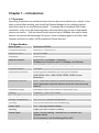
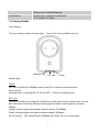
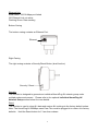
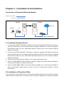
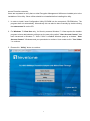
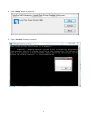
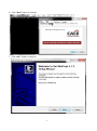
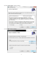
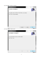
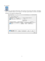
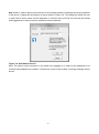
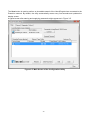
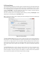
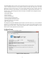
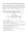
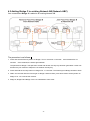
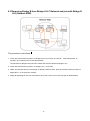
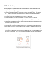
LevelOne
User Manual
PLI-4510
500Mbps Powerline Adapter
with Mains Pass-Through
Ver. 1.0
Table of Contents
Chapter 1 – Introduction ................................................................................................. 2
1.1 Overview ............................................................................................................ 2
1.2 Specification ...................................................................................................... 2
1.3 Casing Details .................................................................................................... 3
1.4 Package Contents ............................................................................................. 5
1.5 System Requirements........................................................................................ 5
Chapter 2 – Installation & Uninstallation ......................................................................... 6
2.1 Installing Powerline Device ................................................................................ 6
2.2 Installation of Powerline Utility ........................................................................... 6
2.3 Uninstallation of Configuration Utility ............................................................... 15
3.1 Main Tab .......................................................................................................... 16
3.2 Privacy Screen ................................................................................................. 21
3.3 Diagnostics Screen .......................................................................................... 22
3.4 About Screen ................................................................................................... 23
Chapter 4 – Individual HomePlug AV Network Stup(Optional....................................... 24
4.1 Creating a new individual HomePlug AV(networkAB) ...................................... 24
4.2 Adding Bridge C to existing Network AB (Network ABC) ................................. 25
4.3 Removing Bridge B from Bridge A & C Network and join with Bridge D & E
(Network BDE) ....................................................................................................... 26
4.4 Troubleshooting ............................................................................................... 27
Safety
FCC
This equipment has been tested and found to comply with Part 15 Class B of the FCC Rules.
Operation is subject to the following two conditions:
(1) This device may not cause harmful interference
(2) This device must accept any interference received, including interference that may cause
undesired operation.
CE
This equipment is in compliance with the requirements of the following regulations: CE Mark,
89/336/EEC
RoHS
This product is RoHS compliant.
1
Chapter 1 – Introduction
1.1 Overview
HomePlug Powerline is an excellent solution that can be used to extend your network. In the
home or small office building, use HomePlug Ethernet Bridges to link multiple locations
without the need to run long Ethernet cables. Combined with a broadband DSL/Cable
connection, every room with electrical power outlets will have easy access to high-speed
Internet connection. With the HomePlug AV speed of up to 500Mbps, this easy-to-setup
solution can provide fast streaming HD movies, online multiplayer games, and other data
intensive activities for today’s HD Entertainment Center demand.
1.2 Specification
Main Chipset
Qualcomm AR7420
Computer Interface
IEEE802.3 ; IEEE802.3u
Data PHY Rate
Up to 500 Mbps
Standards
HomePlug AV
Network Interface
One RJ-45 (10/100Base-T Ethernet)
500Mbps over Powerline and 10/100Mbps over Ethernet
Security
128-bit AES Link Encryption with Key Management
Frequency Band
2-50 Mhz
Modulation Schemes
OFDM Symbol Modulation on Line synchronization
1024/256/64/16/8—QAM, QPSK, BPSK, ROBO Carrier
Modulation
Additional Protocols
Mix of TDMA and CSMA/CA channel access scheme; CO
device generates a periodic beacon carrier for channel access
scheme
Operation Range
Estimated range of 300 meters in wall power lines
Cabling
100Base-T ; Cat. 5 UTP Cable
Operating Temperature
0° C to 40° C ambient temperature
Storage Temperature
-20° C to 70° C ambient temperature
Humidity
10% to 90% maximum (non-condensing)
Power Input
100 ~ 240V @ 50/60Hz Internal
Housing
Plastic (93.7mm x 62mm x 38mm)
Status Lights
Power: On/Off/Flashing 1 second ON, 14 seconds OFF
(Standby Mode)
PLC(Powerline) Link: Red/Orange/Green/Off
2
Ethernet Link: Solid/Off/Flashing
Certifications
HomePlug AV Powerline Certification
FCC Class B / CE Mark
1.3 Casing Details
Front Casing
The front casing contains 3 status lights:
Ethernet Link
Power, PLC Link, and Ethernet Link.
PLC Link
Power
Status Lights
Power
On: This HomePlug AV 500Mbps nano Pass Thru is receiving electrical power
Off: Power off
Flashing Green (1 second ON, 14 second OFF ) : Device in standby mode
PLC Link
The PLC (Powerline) Link light will indicate the overall speed of your network with 3 colors:
Red: Minimum connection indicates weak signal and slower network speed: less than
50Mbps
Orange: Normal signal with standard network speed: 50-99Mbps
Green: Excellent signal with optimal network speed: 100Mbps+
Off: No activity. This HomePlug AV 500Mbps nano Pass Thru is not connected
3
Ethernet Link
Solid Green: 10/100 Mbps port linked
Off: Ethernet Link not active
Flashing Green: Data sending
Bottom Casing
The bottom casing contains an Ethernet Port.
Ethernet
Right Casing
The right casing contains a Security/Reset Button (dual function)
Security / Reset
Security
This function is designed to generate an individual HomePlug AV network group under
multiple nodes environment. Please refer to the optional Individual HomePlug AV
Network Setup section below for more details.
Reset
This function is used to clear ALL data and restore ALL settings to the factory default values.
Note: The HomePlug AV 500Mbps nano Pass Thru must be plugged in to restore it to factory
defaults. Hold the Reset button for 13 sec then release.
4
1.4 Package Contents
Make sure that you have the following items:
- PLI-4510
- RJ-45 Ethernet LAN cable
- Quick Installation Guide
- CD User Manual / QIG/Utility
1.5 System Requirements
- Powerline Ethernet Adaptor can support any Operation System. But the Powerline Utility can only
support Windows 2000/XP/Vista/Windows 7.
- Pentium III 300 MHz or above
- Powerline device
- AC power outlet
5
Chapter 2 – Installation & Uninstallation
Connection of Powerline Ethernet Adapter
Ethernet Cable (RJ-45)
Powerline
Room 1
Room 2
Internet
Notebook
PC
ADSL / Cable Modem
2.1 Installing Powerline Device
1. If you have the SINGLE PACKAGE of Powerline,Connect the supplied RJ45 Ethernet cable from
your PC's Ethernet port to the Powerline Ethernet Adapter's LAN Ports or connect the supplied
RJ45 Ethernet cable from your xDSL/Cable Modem's Ethernet port to the Powerline Ethernet
Adapter's LAN Ports.
2. If you have the TWIN PACKAGE of Powerline, connect the supplied RJ45 Ethernet cable from
your PC's Ethernet port to the Powerline Ethernet Adapter's LAN Ports and connect the supplied
RJ45 Ethernet cable from your xDSL/Cable Modem's Ethernet port to the Powerline Ethernet
Adapter's LAN Ports.
3. Connect the Powerline Ethernet Adapter to your wall-mounted power outlet.
4. Check if the PLC LED of Powerline Ethernet Adapter is ON, the Powerline Ethernet Adapter is
connected and suitable for Internet Connections.
5. Check if the PLC LED is OFF, the Powerline Ethernet Adapter isn’t connected and suitable for
Internet Connections. Please follow next step to have it connected and suitable for Internet
Connections.
2.2 Installation of Powerline Utility
The Configuration Utility enables the users to identify HomePlug devices on the Powerline network;
measures data rate performance, ensures privacy and performs diagnostics by setting user defined
6
secure Powerline networks.
Users are requested to verify that no other Encryption Management Utilities are installed prior to the
installation of this utility. Other utilities should be uninstalled before installing this utility.
1. In order to install, insert Configuration Utility CD-ROM into the computer’s CD-ROM drive. The
program shall run automatically. Alternatively this can also be done manually by double clicking
the autorun.exe file on the CD.
2. For Windows 7 / Vista User only, for Security reasons Windows 7 / Vista requires the installer
program to have administrator privileges so the new policy called " User Account Control " has
been introduced in Windows 7 / Vista. If UAC is enabled Windows pops up a window " User
Account Control " Windows need your permission to continue. User needs to click " Yes / Allow
" to continue.
3. Please click “ Utility” button to continue.
7
4. Click “Setup” button to continue.
5. Click “Confirm” button to continue.
8
6. Click “Next” button to continue.
7. Click “Next ” button to continue.
9
8. Click “I Agree” button to continue
9. Click “Install ” button to continue.
10
10. Click “Flish ” button to continue.
11. Click “Next ” button to continue.
11
12. Click “I Agree & Next ” button to continue.
13. Click “Next ” button to continue.
12
14. Click “Next ” button to continue.
15. Click “Close ” button to exit
13
16. nnected lo
17. You can see your device working well. The top panel of the screen shot shows a Homeplug
device connected locally to your computer. The bottom panel shows one device connected
remotely to the computer running the utility.
14
2.3 Uninstallation of Configuration Utility
1. To uninstall the Configuration Utility, go to the “Control Panel” of your system.
2. Open the “Add/Remove Programs”.
3. Select and double click on the “Powerline Utility” in the Add/Remove Programs Properties.
4. Follow the on screen instructions to uninstall the Powerline Utility.
15
Chapter 3 – Configuration Utility Setup
Introduction
The Configuration Utility enables the users to identify HomePlug devices on the powerline network,
measures data rate performance, ensures privacy and performs diagnostics by setting user defined
secure powerline networks.
The Utility will use a Graphical User Interface (GUI) with limited user selectable options.
3.1 Main Tab
In order to start the utility, double-click the utility icon
on desktop. Figure 3-1 shows the
main screen of the Configuration Utility. The top panel of the screen shot shows a HomePlug AV
device connected locally to the host computer. The bottom panel shows four devices connected
remotely to the computer running the utility.
Figure 3-1: Main Screen with HomePlug AV device Local
16
The Main screen provides a list of all powerline devices logically connected to the computer when
the utility is running.The top panel shows all local HomePlug devices connected to the computer’s
NIC (Network Interface Card). In most cases, only one device will be seen. In situations where there
are more than one local device being connected, such as a USB or an Ethernet adapter, the user
can select the local device by clicking on it and then click the Connect button to its right. The status
area above the button indicates that your PC is connected to that same device. Once connected to
the local device, the utility will automatically scan the power line periodically for any other HomePlug
devices. If no local HomePlug devices are discovered, the status area above the connect button will
indicate with a message ‘NO HOMEPLUG ADAPTERS DETECTED’.
Figure 3-2 illustrates the presence of two local devices connected locally to the computer.
Figure 3-2: Multiple Local Device Connection
The lower panel displays all the HomePlug remote devices, discovered on the current logical
network. The total number of remote devices connected on the same network can be found on top of
the Remote device panel. The Network type (Public or Private) is also displayed based on the
network status of the local device. The scan status option is displayed on the top right corner above
the Remote devices panel showing whether the Autoscan functionality is turned ON or OFF. The
17
following information is displayed for all devices that appear in the lower panel.
Device Name column shows the default device name, which may be user re-defined. A user can
change the name by either using the rename button or by clicking on the name and editing in-place.
An icon is usually shown with the name. By default, the icon is always accompanied by a device
name.
MAC Address column shows the Remote device’s MAC address.
Password column by default is blank and ‘Enter Password’ button can be used to enter it.
To set the Password of the device (required when creating a private network), first select the device
by clicking on its name in the lower panel and then click on the Enter Password button. A dialog box
will appear as shown in Figure 3-3 to type the password. The selected device name is shown above
the password field and the password can be verified by hitting the OK button. The Password field
accepts the Device password in any case formats, with or without dashed between them. If a device
was not found, the user will be notified along with the suggestions to resolve common problems. This
process might take a few seconds to get completed.
Figure 3-3: Set Device Password
18
Add button is used to add a remote device to the existing network by entering the device password
of the device. A dialog box will appear as shown below in Figure 3-4. The dialog box allows the user
to enter both a device name and the password. If a device was not found, the user will be notified
and suggestions to resolve common problems will be presented.
Figure 3-4: Add Remote Device
Note: The device must be present on the power line (plugged in) in order for the password to be
confirmed and added to the network. If the device could not be located, a warning message will be
shown.
19
The Scan button is used to perform an immediate search of the HomePlug devices connected to the
Powerline network. By default, the utility automatically scans every few seconds and updates the
display screen.
A typical screen after naming and supplying passwords might appear as in Figure 3-5.
Figure 3-5: Main Screen of the Configuration Utility
20
3.2 Privacy Screen
The Privacy screen provides the user with an option to maintain security for their logical network and
also to select the devices that has to be included in the network. The appearance is shown in Figure
3-6. All HomePlug devices are shipped using a default logical network (network name), which is
normally “HomePlugAV”. The Privacy dialog screen allows user to change to a private network by
changing the network name (network password) of devices.
The user can always reset to the HomePlug network (Public) by entering “HomePlugAV” as the
network name or by clicking on the “Use Default” button.
Note: Changing the network name to anything other than HomePlugAV will show the network type
on the main screen as Private.
Figure 3-6: Privacy Screen
The Set Local Device Only button can be used to change the network name (network password) of
the local device. If a new network password is entered, all the devices seen on the Main panel prior
to this will be no longer present in the new network, effectively making the local devices not to
communicate to the devices who were in the old logical network. Devices previously set up with the
same logical network (same network name) will appear in the device list afterward selecting this
option.
The Set All Devices button is used to change the logical network of all devices that appear on the
Main panel whose Device’s Password had been entered for the same logical network. A dialog
window will appear to report the success of this operation. For devices whose device password’s
were not entered, this operation will fail and will report a failure message.
21
3.3 Diagnostics Screen
The Diagnostics screen shows System information and a history of all remote devices seen over a
period of time. The appearance is shown in Figure 3-7.
The Upper panel shows technical data concerning software and hardware present on the host
computer which were used to communicate over HomePlug on the Powerline network. It shall
include the following:
- Operating System Platform/Version
- Host Network Name
- User Name
- MAC Address of all NICs (Network interface card) connected to the host
- Identify versions of all Driver DLLs and Libraries used (NDIS) and optionally
- HomePlug chipset manufacturer name
- MAC Firmware Version
- MAC addresses of all devices connected locally to the host
- Version of the Configuration Utility
- Vendor name
Figure 3-7: Diagnostics Screen
22
The Lower panel contains a history of all remote devices seen on the computer over a certain period
of time. All devices that were on the powerline network are listed here along with a few other
parameters. Devices that are active on the current logical network will show a transfer rate in the
Rate column; devices on other networks, or devices that may no longer exist are shown with a “?” in
the Rate column. The following remote device information is available from the diagnostics screen:
- Device Alias Name
- Device MAC Address
- Device Password
- Device Last known rate
- Device Last Known Network name
- HomePlug chipset manufacturer name
- Date device last seen on the network
- MAC Firmware Version.
The diagnostics information displayed may be saved to a text file for later use, or can be printed for
reference for a technical support call. Devices, which are not part of the network anymore, can be
deleted using the delete button. A dialog window pops up with a confirmation message if we try to
delete a device whose password has been entered.
3.4 About Screen
The About screen shows the software version.
Figure 3-8: About dialog screen
23
Chapter 4 – Individual HomePlug AV Network Setup(Optional)
All HomePlug AV 500Mbps nano Pass Thru ship with a default security key so they will automatically
link to all other HomePlug AV 500Mbps nano Pass Thru or Ethernet Bridges sharing the same
electrical lines. If there are other HomePlug AV 500Mbps nano Pass Thru or Ethernet Bridges in
the building (such as in an office or apartment building), you may want to create your own individual
HomePlug AV network group so other HomePlug AV Ethernet Bridges cannot connect to your
network.
This section describes how to use the Security button for configuration in the following situations:
4.1 Creating a new individual HomePlug AV(networkAB)
Two unassociated Bridges (Bridge A and Bridge B) are forming a new network—Network AB
The procedure is as follows:
1. Press and hold the Security button on Bridge A for no more than 10 seconds.
seconds.
Must release after 10
Once released, the Power light will flash.
The password to Bridge A has just been erased and random security key has been generated. It must now
be linked to your network to adopt the new network security key.
2. Press and hold the security button on Bridge B for 10 seconds and release it when the Power light flashes.
The password to Bridge B has just been erased and random security key has been generated.
It must
now be linked to your network to adopt the new network security key.
3. Currently, Bridge A and Bridge B are not networked
4. Press and hold the Security button on Bridge A for 1~3 seconds then release.
5. The Power light on Bridge A starts to flash.
6. Within 120 seconds after the Power light on Bridge A starts to flash, press and hold the Security button on
Bridge B for 1~3 seconds then release.
7. Both Bridge A and Bridge B are now networked together.
24
4.2 Adding Bridge C to existing Network AB (Network ABC)
One unassociated Bridge C is added to an existing Network AB.
The procedure is as follows:
1. Press and hold the Security button on Bridge C for no more than 10 seconds.
seconds.
Must release after 10
Once released, the Power light will flash.
The password to Bridge C has just been erased and random security key has been generated. It must now
be linked to your network to adopt the new network security key.
2. Press and hold the security button on Bridge A for 1~3 seconds. The Power light on Bridge A starts to flash.
3. Within 120 seconds after the Power light on Bridge A starts to flash, press and hold the security button on
Bridge C for 1~3 seconds then release.
4. Bridge A, Bridge B and Bridge C are now networked to each other.
25
4.3 Removing Bridge B from Bridge A & C Network and join with Bridge D
& E (Network BDE)
The procedure is as follows:
1. Press and hold the Security button on Bridge B for no more than 10 seconds.
Must release after 10
seconds. Once released, the Power light will flash.
The password to Bridge B has just been erased and removes itself from Bridge A & C.
2. Press and hold the Security button on Bridge D for 1~3 seconds.
3. Within 120 seconds after the Power light on Bridge D starts to flash, press and hold the Security button on
Bridge B for 1~3 seconds then release.
4. Bridge B and Bridge D are now connected to each other, which in turn becomes part of Network BDE.
26
4.4 Troubleshooting
If your HomePlug AV 500Mbps nano Pass Thru have difficulty communicating with each
other, check the following:
• Try power cycling the unit by unplugging it from the wall for 10 seconds and plugging it in again.
• Hold the security/reset button down for more than 15 seconds to reset to default setting.
AV
The HomePlug
500Mbps nano Pass Thru’s light will flash, the units will reset and attempt to link using default
factory settings.
• Try plugging the HomePlug AV 500Mbps nano Pass Thru into an adjacent plug.
• HomePlug AV 500Mbps nano Pass Thru work better when plugged directly into the wall outlet.
Connecting these Pass Thru units or Ethernet Bridges to a power strip or surge protector may degrade
network performance or completely stop network signals.
• This HomePlug AV 500Mbps nano Pass Thru should not be used on GFI protected outlets as some outlets
will filter out HomePlug Powerline signal.
• This HomePlug AV 500Mbps nano Pass Thru should not be used in areas with excessive heat.
• Certain florescent or incandescent lights are noise sources on the electrical and can degrade performance.
• If your building has more than one circuit breaker box, your HomePlug AV 500Mbps nano Pass Thru may
not be able to connect between the different circuit breaker boxes.
In this case, connect one HomePlug
AV 500Mpbs nano Pass Thru or Ethernet Bridge to a power outlet located on each of the circuit boxes.
Connect Ethernet cable between each of HomePlug AV 500Mbps nano Pass Thru or Ethernet Bridge to link
the different circuits together.
This will allow the HomePlug AV 500Mbps nano Pass Thru from different
circuit breaker boxes to connect.
• To enter standby mode for this device, simply remove the Ethernet cable and wait about 3 minutes.
27