1
Operating Instructions
Included Installation Instructions
Wall Mount Bracket
Model No.
WV-Q122A
The camera in the illustration is separately sold.
Before attempting to connect or operate this product,
please read these instructions carefully and save this manual for future use.
The model number is abbreviated in some descriptions in this manual.
CONTENTS
Preface.......................................................................................................................................................................................3
Precautions................................................................................................................................................................................3
Precautions for installation.........................................................................................................................................................4
Major operating controls............................................................................................................................................................5
Installations/Connections...........................................................................................................................................................6
Specifications...........................................................................................................................................................................14
Standard accessories...............................................................................................................................................................14
2
Preface
This mount bracket is used for installing the color CCTV camera and network camera on a wall.
Refer to the catalog or operating instructions of the camera for further information about the compatible models.
Precautions
Refer installation work to the dealer.
Installation work requires technique and experiences.
Failure to observe this may cause fire, electric shock, injury,
or damage to the product.
Be sure to consult the dealer.
Avoid installing this bracket in the locations where
salt damage occurs or corrosive gas is produced.
Otherwise, the mounting portions will deteriorate and accidents such as a fall of this product may occur.
The screws and bolts must be tightened to the specified torque.
Loosening of mounting screws or bolts may cause a fall of
the product resulting in injury or accidents.
Do not use this bracket except with suitable cameras
Failure to observe this may cause a drop resulting in injury.
Select an installation area that can support the total
weight.
Selecting an inappropriate installation surface may cause
this product to fall down or topple over, resulting in injury or
accidents.
Installation work shall be started after sufficient reinforcement.
Do not strike or give a strong shock to this product.
Failure to observe this may cause fire or injury.
Install this product in a location high enough to avoid
people and objects from bumping the product.
Failure to observe this may cause injury.
Do not hang down from this product or use this product as a pedestal.
Failure to observe this may cause a drop resulting in accidents.
Do not install the product in a windy place.
Installation of the product in wind with a speed of 40 m/s or
more may cause a drop resulting in accidents.
The measures of protection against snowfall shall be
taken.
Weight of snow may cause a fall of the product resulting in
injury or accidents.
Protect the product against snowfall by installing under
eaves.
Do not rub the edges of metal parts with your hand.
Strong rubbing may cause injury.
Periodic inspections shall be conducted.
Rust on the metal parts or screws may cause a fall of the
product resulting in injury or accidents.
Consult the dealer for the inspections.
The measures of protection against a fall of this product shall be taken.
Failure to observe this may cause a drop resulting in injury
or accidents.
Be sure to install the safety wire.
Do not install this product in locations subject to
vibration.
Loosening of mounting screws or bolts may cause a fall of
the product resulting in injury or accidents.
3
Precautions for installation
Panasonic assumes no responsibility for injuries or property damage resulting from failures arising out of improper
installation or operation inconsistent with this documentation.
The installation should comply with local electrical
code.
Before start the installation/connection, check and prepare
the required devices and cables. Before starting the connection, turn the power of the devices including the camera
and the PC off.
Refer installation work to the dealer. Failure to
observe this may cause fire, electric shock, injury, or
damage to the product.
Power supply
Use a power supply device equipped with the ON-OFF
switch for servicing. When the power cord of the product is
connected to the power supply device, the power will be
supplied to the product. When the product is supplied, the
product will perform panning, tilting, zooming and focusing.
Before cleaning the product, make sure that the power
cable is not connected to the main power supply.
Installation area for this product
Consult the dealer about the installation area to select a
strong wall area.
• Screws used for installing this product on a wall are not
supplied. Prepare them according to the material and
strength of the area where the product is to be installed.
Recommended screw: M8 x 4 pcs.
Minimum pull-out strength (per 1 pc.): 823 N {185 lbf}
• Do not mount the product on a plaster board or a
wooden section because they are too weak. If the product is unavoidably mounted on such a section, the section shall be sufficiently reinforced.
Screw tightening
• The screws and bolts must be tightened with an appropriate tightening torque according to the material and
strength of the installation area.
• Do not use an impact driver. Use of an impact driver
may damage the screws or cause tightening excessively.
• When a screw is tightened, make the screw at a right
angle to the surface. After tightening the screws or
bolts, perform checks to ensure that the tightening is
sufficient enough so that there is no movement or looseness.
The protection cover attached to the camera unit
shall be removed after completion of the installation.
(rain wash coating model)
Make sure to remove this product if it will no longer
be used.
Mounting method for this product
This product is designed to be used as a pendant mount
camera. If the product is mounted on a desktop or at a
slant, it may not work correctly and its lifetime may be shortened.
Take notice of humidity.
Install this product when the humidity is low. If this product
is installed during rainfall or at a high humidity, the inside
may be exposed to moisture and the dome cover may
become foggy.
Protection from lightning
When cables are used outdoors, there is a chance that they
may be affected by lightning. In this case, install a lightning
arrester just before where the cables connect to the camera.
Matters you should know at installation work
Compatibility of devices are restricted. Before connections,
check the ratings and dimensions of the devices to be used.
Refer to "Panasonic CCTV System General Catalog" or contact your dealer for further information.
Do not place this product in the following places:
• Locations where a chemical agent is used such as a
swimming pool
• Locations subject to moisture or oil smoke such as a
kitchen
• Locations that have a specific environment that is subject to an inflammable atmosphere or solvents
• Locations where radiation, x-ray, intense radio wave, or
strong magnetism is produced
4
• Locations where corrosive gas is produced, locations
where it may be damaged by briny air such as seashores
• Locations where the temperature is not within the specified range (–50 °C to +55 °C {–58 °F to 131 °F})
• Locations subject to vibrations, such as on vehicles,
marine vessels, or above product lines (This product is
not designed for onvehicle use.)
• Locations subject to condensation as the result of
severe changes in temperature (In case of installing the
product in such locations, the dome cover may become
foggy or condensation may be caused on the cover.)
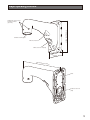
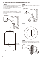
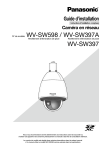
Major operating controls
220 mm {8-21/32 inches}
Hexagonal screw hole for
mounting camera
(4 points)
Camera mounting part
Wire hook section
Cable access hole (front)
m
120 m hes}
inc
2
3
/
3
{4-2
269 mm
{10-19
/32 inc
hes}
Plate
Cable access hole
(rear)
5
Installations/Connections
Be sure to read "Precautions" and "Precautions for installation" before installation.
Read the operating instructions for the camera to be installed as well. The Operating Instructions mainly describe for installing a
network camera.
The basic flow of the installation operation is the same as the one for the color CCTV camera.
The flow of how to install the wall mount bracket is described as follows.
[1] How to detach the housing base (☞ 6 page)
Remove the housing base and attachment pipe from the camera body.
[2] Attaching the mount bracket (☞ 8 page)
■ When laying cables through the cable access hole (front) (☞ 8 page)
■ When laying cables after drilling a hole through the wall (☞ 10 page)
[3] Mounting of the camera body on the mount bracket (☞ 12 page)
Secure the camera body to the housing base.
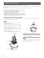
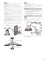
[1] How to detach the housing base
Before attaching the camera to the wall mount bracket, detach the housing base and attachment pipe from the camera so that
installation and connections can be performed.
Step 1
Remove the fixing screws (3 pcs.*) that are securing the
housing base and the camera.
The removed screws will be required when attaching the
camera to the housing base. Use caution not to lose these
screws.
*Special screw (fixing screw): These screws are hexagon
screws. Use an M5 hexagon wrench.
There are 2 types of wrenches to be used; one is hexagonal wrench "for M5" (WV-SW598) and the other is hexagonal wrench "for M6".
Refer to the Operating Instructions of the camera for the
wrench to be used, which depends on models.
Fixing screws (3 pcs.)
Protection cover
IMPORTANT:
• The protection cover attached to the camera unit shall
be removed after completion of the installation. (Only for
rain-wash coating model)
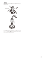
Step 2
Housing base
Camera
Protection cover
6
To separate the housing base from the camera, turn the
housing base to the direction of the arrow as illustrated.
(Refer to the illustration in Step 1.)
Step 3
Remove the attachment pipe from the upper base by loosening 4 screws.
Attachment pipe
Go to "■ When laying cables through the cable access hole
(front)" (☞ 8 page) or "■ When laying cables after drilling a
hole through the wall" (☞ 10 page).
7
[2] Attaching the mount bracket
The installation of the wall mount bracket is roughly divided into 2 methods.
Refer to the applicable description.
■W
hen laying cables through the cable access hole (front) (☞ 8 page)
■W
hen laying cables after drilling a hole through the wall (☞ 10 page)
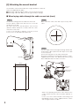
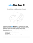
■ When laying cables through the cable access hole (front)
Step 1
Step 2
Decide the mounting position and drill a hole in the wall.
Procure 4 pieces of M8 screws and anchors to secure the
this bracket on the wall.
All screws and anchors shall be stainless steel. The hole
diameter shall be decided in accordance with the screws
and anchors to be used.
A hole on the wall with a diameter of 30 mm {ø1-3/16
inches} or less can be hidden with this bracket.
Make a slit in the center of the cable cap (accessory) with a
cutter.
Step 3
Pass the cables from the housing base through this bracket,
and mount the cable cap that was slit in Step 2 on the cable
access hole (front).
Secure the housing base to the wall mount bracket.
Attach the housing base to this bracket using the 4 screws*
supplied with the camera. The "REAR" mark of the housing
base shall be directed to the wire hook section.
80 mm
{3-5/32 inches}
Wire hook
section
180 mm
{7-3/32 inches}
Cable access
hole (front)
* Refer to the Operating Instructions of the camera for the
screws and the wrenches to be used, which depends on
models.
For the case of the camera with M5 screws being used
(WV-SW598): Use the screws supplied with the camera
and a hexagonal wrench "for M5".
8
For the case of the camera with M6 screws being used:
Use the screws supplied with the bracket and a hexagonal
wrench "for M6".
(Recommended tightening torque (for common use in M5
and M6): 2.45 N.m {1.81 lbf·ft})
Step 7
Connect the cables to the camera.
Connect the cables from the housing base with the cables
on the wall.
After cable connection, seal the connecting portion with
waterproof tape (locally procured).
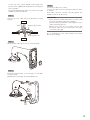
Step 4
Seal the slit of the cable cap for the prevention of water
leakage.
Outside
Sealant (locally procured)
Cable
Cable cap (with a slit)
IMPORTANT:
• These operations shall be performed in accordance with
the electric installation engineering standards.
Perform sealing to prevent the connecting portion of the
cables from being exposed.
Moisture may come into the camera from the gap
among the cables and cause the inside of the dome
cover to become foggy.
Go to "[3] Mounting of the camera body on the mount
bracket" (☞ 12 page).
Inside
Step 5
Mount another cable cap (accessory) on the rear plate.
Step 6
Mount the mount bracket on the wall with 4 screws (M8:
locally procured).
Minimum pull-out strength: 823 N {185 lbf}/per 1 pc.
9
■ When laying cables after drilling a hole through the wall
Step 2
Step 1
Decide the mounting position, and drill a hole for a screw or
an anchor and a hole for cable installation in the wall.
Procure 4 pieces of M8 screws and anchors to secure the
this bracket on the wall.
All screws and anchors shall be stainless steel. The hole
diameter shall be decided in accordance with the screws
and anchors to be used.
A hole on the wall with a diameter of 30 mm {ø 1-3/16
inches} or less for a screw or an anchor can be hidden with
this bracket.
Mount the cable cap (accessory) on the cable access hole
(front).
Step 3
Make a slit in the center of another cable cap (accessory)
with a cutter.
180 mm
{7-3/32 inches}
120 mm
{4-3/4 inches}
80 mm
{3-5/32 inches}
Hole for cable
installation: ø38 mm
{ø1-1/2 inches}
10
Step 4
Remove the 4 screws from the rear side of the bracket,
remove the plate, and mount the cable cap that was slit in
Step 3.
Step 5
Step 6
Lay the cables from the housing base via this blacket into
the slit cable cap.
Secure the housing base to the wall mount bracket.
Attach the housing base to the mount bracket using the 4
screws*.
The "REAR" mark of the housing base shall be directed to
the wire hook section.
*Refer to the Operating Instructions of the camera for the
screws and the wrenches to be used, which depends on
models.
For the case of the camera with M5 screws being used
(WV-SW598):
Use the screws supplied with the camera and a hexagonal
wrench "for M5".
For the case of the camera with M6 screws being used:
Use the screws supplied with the bracket and a hexagonal
wrench "for M6".
(Recommended tightening torque (for common use in M5
and M6): 2.45 N·m {1.81 lbf·ft})
Secure the plate with the 4 screws removed in Step 4 on
the rear side of the bracket, and seal the slit of the cable
cap.
(Recommended tightening torque: 0.78 N·m {0.58 lbf·ft})
Connect the cables to the camera.
Connect the cables from the housing base with the cables
coming through the wall.
After cable connection, seal the connecting portion with
waterproof tape (locally procured).
IMPORTANT:
• These operations shall be performed in accordance with
the electric installation engineering standards.
Perform sealing to prevent the connecting portion of the
cables from being exposed.
Moisture may come into the camera from the gap
among the cables and cause the inside of the dome
cover to become foggy.
Step 7
Mount this bracket on the wall with 4 screws (M8: locally
procured).
Minimum pull-out strength: 823 N {185 lbf}/per 1 pc.
Go to "[3] Mounting of the camera body on the mount
bracket" (☞ 12 page).
Outside
Sealant (locally procured)
Cable
Cable cap (with a slit)
Inside
11
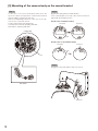
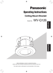
[3] Mounting of the camera body on the mount bracket
Step 1
Step 2
For the case of color CCTV camera, peel off the seal on the
top of the camera, and specify the communication method
and unit address using the DIP switches.
Refer to the Operating Instructions of the color CCTV camera for how to set the DIP switch.
Put the seal back after specifying them.
Communication method: specifying with SW2
Unit address: specifying with SW1
Align the flat spring with the START position.
If not, rotate the plate on the top of the camera clockwise to
align it with the "START" position.
For the case of network camera
Flat spring
Projections
Camera top
Plate
For the case of color CCTV camera
S TA R
T
Flat spring
Projections
5Set
1
SW
RS48
ting
SW2
S TA R T
Plate
S TA R
T
Seal
Step 3
ON
Engage the safety wire with the wire hook section.
1
2
3
4
5
DIP
6
7
8
1
SW
ON
1
3
2
4
2
P
DI
SW
DIP switch
Safety wire
12
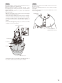
Step 4
Step 5
When attaching the camera to the housing base, the positioning pin shall be on the "REAR" side.
Make sure that the camera is securely attached to the
mount bracket by turning the bracket counterclockwise
(seen from below).
Tighten them firmly with the 3 screws* that have been
removed in Step 1.
*Special screw (fixing screw): These screws are hexagon
screws. Use a hexagon wrench.
There are 2 types of wrenches to be used; one is hexagonal wrench "for M5" (WV-SW598) and the other is hexagonal wrench "for M6". Refer to the Operating Instructions of
the camera for the wrench to be used, which depends on
models.
(Recommended tightening torque (for common use in M5
and M6): 2.45 N·m {1.81 lbf·ft})
Mount the front and rear sunshields, and then remove the
protection cover.
Refer to the Operating Instructions of the camera for further
information.
Removal of the protection cover is described only for rain
wash coating model.
Housing base
Fixing screws (3 pcs.)
START
Front/rear sunshields
(supplied with the camera)
Housing base
Positioning
pin
Camera
Protection cover
*The illustration above is provided for describing the top of
the camera, and therefore, this bracket is omitted.
13
Specifications
Ambient operating temperature:
Dimensions:
Mass:
Finish:
–50 °C to +55 °C {–58 °F to 131 °F}
120 mm (W) x 220 mm (H) x 269 mm (D)
{4-23/32 inches (W) x 8-21/32 inches (H) x 10-19/32 inches (D)}
Approx. 2 kg {4.42 lbs}
Aluminum die cast (coating color: fine silver (901))
Weight and dimensions indicated are approximate.
Specifications are subject to change without notice.
Standard accessories
Operating Instructions (this document)............................................... 1 set
The following are for installation
Cable cap........................................................................................ 2 pcs.
Camera mounting screw (Hexagon screw (M6))............................... 4 pcs.
14
15
For U.S. and Canada:
For Europe and other countries:
Panasonic System Communications Company of North America,
Unit of Panasonic Corporation of North America
Panasonic Corporation
www.panasonic.com/business/
For customer support, call 1.800.528.6747
Three Panasonic Way, Secaucus, New Jersey 07094 U.S.A.
Panasonic Canada Inc.
5770 Ambler Drive, Mississauga, Ontario, L4W 2T3 Canada
(905)624-5010
www.panasonic.ca
© Panasonic System Networks Co., Ltd. 2013
http://panasonic.net
Importer's name and address to follow EU rules:
Panasonic Testing Centre
Panasonic Marketing Europe GmbH
Winsbergring 15, 22525 Hamburg, Germany
Ns0913-0
PGQX1409ZA
Printed in China