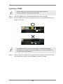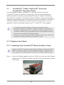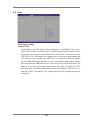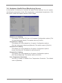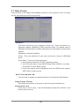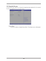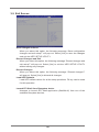
1
C216 WS
User Manual
Version 1.0
Published December 2012
Copyright©2012 ASRock INC. All rights reserved.
1
Copyright Notice:
No part of this manual may be reproduced, transcribed, transmitted, or translated in
any language, in any form or by any means, except duplication of documentation by
the purchaser for backup purpose, without written consent of ASRock Inc.
Products and corporate names appearing in this manual may or may not be registered trademarks or copyrights of their respective companies, and are used only for
identiication or explanation and to the owners’ beneit, without intent to infringe.
Disclaimer:
Speciications and information contained in this manual are furnished for informational use only and subject to change without notice, and should not be constructed
as a commitment by ASRock. ASRock assumes no responsibility for any errors or
omissions that may appear in this manual.
With respect to the contents of this manual, ASRock does not provide warranty of
any kind, either expressed or implied, including but not limited to the implied warranties or conditions of merchantability or itness for a particular purpose.
In no event shall ASRock, its directors, oficers, employees, or agents be liable for
any indirect, special, incidental, or consequential damages (including damages for
loss of proits, loss of business, loss of data, interruption of business and the like),
even if ASRock has been advised of the possibility of such damages arising from
any defect or error in the manual or product.
This device complies with Part 15 of the FCC Rules. Operation is subject to the following two conditions:
(1) this device may not cause harmful interference, and
(2) this device must accept any interference received, including interference that
may cause undesired operation.
CALIFORNIA, USA ONLY
The Lithium battery adopted on this motherboard contains Perchlorate, a toxic
substance controlled in Perchlorate Best Management Practices (BMP) regulations
passed by the California Legislature. When you discard the Lithium battery in California, USA, please follow the related regulations in advance.
“Perchlorate Material-special handling may apply, see
www.dtsc.ca.gov/hazardouswaste/perchlorate”
ASRock Website: http://www.asrock.com
2
Contents
1 Introduction ........................................................ 5
1.1
1.2
1.3
1.4
1.5
1.6
Package Contents .........................................................
Speciications ................................................................
Unique Features ............................................................
Motherboard Layout ......................................................
I/O Panel ......................................................................
Block Diagram .............................................................
5
6
10
11
12
14
2 Installation .......................................................... 15
2.1
2.2
2.3
2.4
2.5
2.6
2.7
Screw Holes...................................................................
Pre-installation Precautions .........................................
CPU Installation .............................................................
Installation of Heatsink and CPU fan .............................
Installation of Memory Modules (DIMM) ........................
Expansion Slots (PCI and PCI Express Slots) ....................
CrossFireXTM, 3-Way CrossFireXTM and Quad
CrossFireXTM Operation Guide .......................................
2.8 Surround Display Feature .............................................
2.9 Jumpers Setup ..........................................................
2.10 Onboard Headers and Connectors ............................
2.11 Dr. Debug ...................................................................
2.12 Teaming Function Operation Guide ............................
15
15
16
18
19
21
23
28
31
32
37
38
3 UEFI SETUP UTILITY .......................................... 42
3.1 Introduction ....................................................................
3.1.1 UEFI Menu Bar ....................................................
3.1.2 Navigation Keys ...................................................
3.2 Main Screen...................................................................
3.3 OC Tweaker Screen ......................................................
3.4 Advanced Screen...........................................................
3.4.1 CPU Coniguration ...............................................
3.4.2 North Bridge Coniguration...................................
3.4.3 South Bridge Coniguration ..................................
3.4.4 Storage Bridge Coniguration ...............................
3.4.5 Super IO Coniguration ........................................
3.4.6 ACPI Coniguration...............................................
3.4.7 USB Coniguration ...............................................
3.5 Tool ................................................................................
3.6 Hardware Health Event Monitoring Screen ...................
3.7 Boot Screen ...................................................................
3.8 Security Screen .............................................................
3
42
42
43
43
44
49
50
52
53
54
56
57
59
60
61
62
64
3.9 Exit Screen .................................................................... 65
4 Software Support ............................................... 66
4.1 Install Operating System................................................
4.2 Support CD Information .................................................
4.2.1 Running Support CD ............................................
4.2.2 Drivers Menu ........................................................
4.2.3 Utilities Menu........................................................
4.2.4 Contact Information ..............................................
66
66
66
66
66
66
5 Troubleshooting ................................................ 67
5.1 Troubleshooting Procedures .......................................... 67
5.2 Technical Support Procedures ....................................... 69
5.3 Returning Merchandise for Service ............................... 69
4
Chapter 1: Introduction
Thank you for purchasing ASRock C216 WS motherboard, a reliable motherboard
produced under ASRock’s consistently stringent quality control. It delivers excellent
performance with robust design conforming to ASRock’s commitment to quality and
endurance.
In this manual, chapter 1 and 2 contains introduction of the motherboard and stepby-step guide to the hardware installation. Chapter 3 and 4 contains the coniguration guide to BIOS setup and information of the Support CD.
Because the motherboard speciications and the BIOS software might be
updated, the content of this manual will be subject to change without notice. In case any modiications of this manual occur, the updated version
will be available on ASRock website without further notice. You may ind
the latest VGA cards and CPU support lists on ASRock website as well.
ASRock website http://www.asrock.com
If you require technical support related to this motherboard, please visit
our website for speciic information about the model you are using.
www.asrock.com/support/index.asp
1.1 Package Contents
ASRock C216 WS Motherboard
(ATX Form Factor: 12.0-in x 9.6-in, 30.5 cm x 24.4 cm)
ASRock C216 WS User Manual
ASRock C216 WS Support CD
6 x Serial ATA (SATA) Data Cables (Optional)
1 x I/O Panel Shield
ASRock Reminds You...
To get better performance in Windows® 8 / 8 64-bit / 7 / 7 64-bit, it is
recommended to set the BIOS option in Storage Coniguration to AHCI
mode.
5
1.2 Speciications
Platform
CPU
Chipset
Memory
Expansion Slot
Graphics
- ATX Form Factor: 12.0-in x 9.6-in, 30.5 cm x 24.4 cm
- Premium Gold Capacitor design (100% Japan-made
high-quality Conductive Polymer Capacitors)
- Intel® Socket 1155 for 3rd/2nd Generation CoreTM i7/CoreTM i5/
CoreTM i3 Processors
- Intel® Socket 1155 for Intel® E3-1200/12x5 v2 processors
- Supports Intel® 32 nm CPU
- Supports Intel® 22 nm CPU
- Digi Power Design
- 8 + 4 Power Phase Design
- Supports Intel® Turbo Boost 2.0 Technology
- Intel® C216
- Dual Channel DDR3 Memory Technology
- 4 x DDR3 DIMM slots
- Supports DDR3 1600/1333/1066 ECC/non-ECC,
un-buffered memory
* ECC memory is supported with Xeon® E3 CPU only.
- Max. capacity of system memory: 32GB (see CAUTION 1)
- 2 x PCI Express 3.0 x16 slots (PCIE2/PCIE4: Single at x16
(PCIE2) mode or dual at x8 (PCIE2) / x8 (PCIE4) mode)
(see CAUTION 2)
* PCIE 3.0 is only supported with Intel® Ivy Bridge CPU. With
Intel® Sandy Bridge CPU, it only supports PCIE 2.0.
- 1 x PCI Express 2.0 x16 slot (PCIE5: x4 mode)
- 2 x PCI Express 2.0 x 1 slots
- 2 x PCI slots
- Supports AMD Quad CrossFireXTM, 3-Way CrossFireXTM and
CrossFireXTM
* Intel® HD Graphics Built-in Visuals and the VGA outputs can
be supported only with processors which are GPU
integrated.
- Supports Intel® HD Graphics Built-in Visuals: Intel® Quick
Sync Video 2.0, Intel® InTruTM 3D, Intel® Clear Video HD
Technology, Intel® InsiderTM, Intel® HD Graphics 2500/4000
with Intel® Ivy Bridge CPU
- Supports Intel® HD Graphics Built-in Visuals: Intel® Quick
Sync Video, Intel® InTruTM 3D, Intel® Clear Video HD
Technology, Intel® HD Graphics 2000/3000, Intel® Advanced
Vector Extensions (AVX) with Intel® Sandy Bridge CPU
6
Audio
LAN
Storage
Rear Panel I/O
- Pixel Shader 5.0, DirectX 11 with Intel® Ivy Bridge CPU.
Pixel Shader 4.1, DirectX 10.1 with Intel® Sandy Bridge
CPU.
- Max. shared memory 1760MB with Intel® Ivy Bridge CPU.
Max. shared memory 1759MB with Intel® Sandy Bridge
CPU.
- Supports HDMI 1.4a Technology with max. resolution up to
1920x1200 @ 60Hz
- Supports Auto Lip Sync, Deep Color (12bpc), xvYCC and
HBR (High Bit Rate Audio) with HDMI (Compliant HDMI
monitor is required) (see CAUTION 3)
- Supports HDCP function with HDMI port
- Supports Full HD 1080p Blu-ray (BD) / HD-DVD playback
with HDMI port
- 7.1 CH HD Audio with Content Protection
(Realtek ALC892 Audio Codec)
- Premium Blu-ray audio support
- PCIE x1 Gigabit LAN 10/100/1000 Mb/s
- Broadcom BCM57781
- Supports Wake-On-LAN
- Supports Energy Eficient Ethernet 802.3az
- Supports Dual LAN with Teaming function
- Supports PXE
- 2 x SATA3 6.0 Gb/s connectors by Intel® C216, support
RAID (RAID 0, RAID 1, RAID 5, RAID 10, Intel Rapid
Storage and Intel Smart Response Technology), NCQ, AHCI
and “Hot Plug” functions
- 4 x SATA3 6.0 Gb/s connectors by ASMedia ASM1061,
support NCQ, AHCI and “Hot Plug” functions (SATA3_A4
connector is shared with eSATA3 port)
- 4 x SATA2 3.0 Gb/s connectors by Intel® C216, support
RAID (RAID 0, RAID 1, RAID 5, RAID 10, Intel Rapid
Storage and Intel Smart Response Technology), NCQ, AHCI
and Hot Plug functions
I/O Panel
- 1 x PS/2 Keyboard/Mouse Port
- 1 x HDMI Port
- 1 x Optical SPDIF Out Port
- 4 x Ready-to-Use USB 2.0 Ports
- 1 x eSATA3 Connector
- 6 x Ready-to-Use USB 3.0 Ports
7
USB3.0
Connector
BIOS Feature
Support CD
Hardware
Monitor
OS
- 2 x RJ-45 LAN Ports with LED (ACT/LINK LED and SPEED
LED)
- 1 x IEEE 1394 Port
- HD Audio Jack: Rear Speaker/Central/Bass/Line in/Front
Speaker/Microphone
- 2 x Rear USB 3.0 ports by Intel® C216, support
USB 1.1/2.0/3.0 up to 5Gb/s
- 4 x Rear USB 3.0 ports by Etron EJ188H, support
USB 1.1/2.0/3.0 up to 5Gb/s
- 1 x Front USB 3.0 header by Intel® C216 (supports 2 USB 3.0
ports), supports USB 1.1/2.0/3.0 up to 5Gb/s
- 1 x IR header
- 1 x COM port header
- 1 x HDMI_SPDIF header
- 1 x IEEE 1394 header
- 1 x Power LED header
- 2 x CPU Fan connectors (1 x 4-pin, 1 x 3-pin)
- 3 x Chassis Fan connectors (1 x 4-pin, 2 x 3-pin)
- 1 x Power Fan connector (3-pin)
- 24 pin ATX power connector
- 8 pin 12V power connector
- Front panel audio connector
- 2 x USB 2.0 headers (support 4 USB 2.0 ports)
- 1 x USB 3.0 header (supports 2 USB 3.0 ports)
- 1 x Dr. Debug (7-Segment Debug LED)
- 64Mb AMI UEFI Legal BIOS
- ACPI 1.1 Compliance Wake Up Events
- SMBIOS 2.3.1 Support
- CPU Core, IGPU, DRAM, 1.8V PLL, VTT, VCCSA Voltage
Multi-adjustment
- Drivers, Utilities, AntiVirus Software (Client OS, Trial
Version)
- CPU Temperature Sensing
- Chassis Temperature Sensing
- CPU/Chassis/Power Fan Tachometer
- CPU/Chassis Quiet Fan (Allows CPU Fan Speed AutoAdjust by CPU Temperature)
- CPU/Chassis Fan Multi-Speed Control
- Voltage Monitoring: +12V, +5V, +3.3V, CPU Vcore
- Microsoft® Windows® 8 / 8 64-bit / 7 / 7 64-bit compliant
8
Certiications
- FCC, CE, WHQL
- ErP/EuP Ready (ErP/EuP ready power supply is required)
* For detailed product information, please visit our website: http://www.asrock.com
WARNING
Please realize that there is a certain risk involved with overclocking,
including adjusting the setting in the BIOS, applying Untied Overclocking
Technology, or using third-party overclocking tools. Overclocking may
affect your system’s stability, or even cause damage to the components
and devices of your system. It should be done at your own risk and
expense. We are not responsible for possible damage caused by
overclocking.
CAUTION!
1. Due to the operating system limitation, the actual memory size
may be less than 4GB for the reservation for system usage under Windows® 8 / 7. For Windows® OS with 64-bit CPU, there is
no such limitation.
2. Only PCIE2 and PCIE4 slots support Gen 3 speed. To run the
PCI Express in Gen 3 speed, please install an Ivy Bridge CPU.
If you install a Sandy Bridge CPU, the PCI Express will run only
at PCI Express Gen 2 speed.
3. xvYCC and Deep Color are only supported under Windows® 8
64-bit / 8 / 7 64-bit / 7. Deep Color mode will be enabled only
if the display supports 12bpc in EDID. HBR is supported under
Windows® 8 64-bit / 8 / 7 64-bit / 7.
9
1.3 Unique Features
ASRock Instant Flash
ASRock Instant Flash is a BIOS lash utility embedded in Flash
ROM. This convenient BIOS update tool allows you to update
system BIOS without entering operating systems irst like MSDOS or Windows®. With this utility, you can press the <F6> key
during the POST or the <F2> key to enter into the BIOS setup
menu to access ASRock Instant Flash. Just launch this tool and
save the new BIOS ile to your USB lash drive, loppy disk or
hard drive, then you can update your BIOS only in a few clicks
without preparing an additional loppy diskette or other complicated lash utility. Please be noted that the USB lash drive or
hard drive must use FAT32/16/12 ile system.
ASRock Crashless BIOS
ASRock Crashless BIOS allows users to update their BIOS
without fear of failing. If power loss occurs during the BIOS update process, ASRock Crashless BIOS will automatically inish
the BIOS update procedure after regaining power. Please note
that BIOS iles need to be placed in the root directory of your
USB disk. Only USB2.0 ports support this feature.
10
1.4 Motherboard Layout
2
1
3
6
5
4
24.4cm (9.6 in)
PS2
Keyboard/
Mouse
USB 3.0
T: USB0
B: USB1
CPU_FAN2
CPU_FAN1
ATX12V1
ATXPWR1
DDR3_B2 (64 bit, 240-pin module)
DDR3_A2 (64 bit, 240-pin module)
Top:
RJ-45
37
DDR3_B1 (64 bit, 240-pin module)
USB 3.0
T: USB4
B: USB5
LAN
PHY
DDR3_A1 (64 bit, 240-pin module)
ESATA_1
IEEE 1394
USB 2.0
T: USB4
B: USB5
PCI Express 3.0
USB 2.0: USB3
USB 2.0: USB2
Top:
RJ-45
30.5cm (12.0 in)
HDMI1
USB 3.0
T: USB2
B: USB3
7
Center:
FRONT
Bottom:
MIC IN
Top:
LINE IN
Bottom:
Optical
SPDIF
Center:
REAR SPK
Top:
Central/Bass
8
LAN
PHY
PWR_FAN1 CHA_FAN2
36
USB3_6_7
PCIE1
9
34
SATA3_0_1 SATA3_A1_A2 SATA3_A3_A4
35
PCIE2
AUDIO
CODEC
PCI1
Super
I/O
SATA2_2_3
Intel
C216
CMOS
Battery
PCIE3
32
SATA2_4_5
33
PCIE4
31
30
PCI2
RoHS
10
11
12
13
14
15
C216 WS
29
28
1
HDMI_SPDIF1
USB8_9
CHA_FAN1
IR1
1
1
PLED PWRBTN
1
1
1
1
1
CHA_FAN3
27
6
7
8
9
10
11
12
13
14
15
16
17
18
PLED1
1
USB6_7
CLRCMOS1
1
1
2
3
4
5
SPEAKER1
1
FRONT_1394
COM1
HD_AUDIO1
64Mb
BIOS
Dr.
Debug
PCIE5
26
25
24
23
1155-Pin CPU Socket
ATX 12V Power Connector (ATX12V1)
CPU Fan Connector (CPU_FAN1)
CPU Fan Connector (CPU_FAN2)
2 x 240-pin DDR3 DIMM Slots
(DDR3_A1, DDR3_B1)
2 x 240-pin DDR3 DIMM Slots
(DDR3_A2, DDR3_B2)
ATX Power Connector (ATXPWR1)
USB 3.0 Header (USB3_6_7)
Intel C216 Chipset
SATA3 Connectors (SATA3_A3_A4)
SATA3 Connectors (SATA3_A1_A2)
SATA3 Connectors (SATA3_0_1)
SATA2 Connectors (SATA2_2_3)
SATA2 Connectors (SATA2_4_5)
Dr. Debug
Power LED Header (PLED1)
Chassis Speaker Header (SPEAKER1)
System Panel Header (PANEL1)
22
19
20
21
22
23
24
25
26
27
28
29
30
31
32
33
34
35
36
37
11
21
20
19
HDLED RESET
PANEL1
18 17 16
Chassis Fan Connector (CHA_FAN3)
USB 2.0 Header (USB_6_7)
USB 2.0 Header (USB_8_9)
Chassis Fan Connector (CHA_FAN1)
Clear CMOS Jumper (CLRCMOS1)
Front Panel IEEE 1394 Header
(FRONT_1394)
Infrared Module Header (IR1)
COM Port Header (COM1)
Front Panel Audio Header (HD_AUDIO1)
HDMI_SPDIF Header (HDMI_SPDIF1)
PCI Express 2.0 x16 Slot (PCIE5)
PCI Slot (PCI2)
PCI Express 3.0 x16 Slot (PCIE4)
PCI Express 2.0 x1 Slot (PCIE3)
PCI Slot (PCI1)
PCI Express 3.0 x16 Slot (PCIE2)
PCI Express 2.0 x1 Slot (PCIE1)
Power Fan Connector (PWR_FAN1)
Chassis Fan Connector (CHA_FAN2)
1.5 I/O Panel
17
1
*2
3
*4
5
6
7
8
** 9
3
2
1
16
15
14
PS/2 Keyboard/Mouse Port (Purple/Green)
LAN RJ-45 Port
USB 2.0 Ports (USB45)
LAN RJ-45 Port
Central / Bass (Orange)
Rear Speaker (Black)
Optical SPDIF Out Port
Line In (Light Blue)
Front Speaker (Lime)
13
10
11
12
*** 13
14
15
16
17
4
5
8
6
9
7
10
11
12
Microphone (Pink)
USB 3.0 Ports (USB3_45)
IEEE 1394 Port
eSATA3 Port (ESATA_1)
USB 3.0 Ports (USB3_23)
USB 2.0 Ports (USB23)
HDMI Port (HDMI1)
USB 3.0 Ports (USB3_01)
* There are two LED next to the LAN port. Please refer to the table below for the LAN port LED
indications.
LAN Port LED Indications
Activity/Link LED
Status
Description
Status
Off
No Link
Blinking Data Activity
On
Link
Off
Orange
Green
ACT/LINK
LED
SPEED LED
Description
10Mbps connection
100Mbps connection
1Gbps connection
SPEED
LED
LAN Port
** If you use 2-channel speaker, please connect the speaker’s plug into “Front Speaker Jack”.
See the table below for connection details in accordance with the type of speaker you use.
TABLE for Audio Output Connection
Audio Output Channels Front Speaker Rear Speaker
(No. 9)
(No. 6)
2
4
6
8
V
V
V
V
-V
V
V
12
Central / Bass
(No. 5)
--V
V
Line In or
Side Speaker
(No. 8)
---V
To enable Multi-Streaming function, you need to connect a front panel audio cable to the front
panel audio header. After restarting your computer, you will ind “Mixer” tool on your system.
Please select “Mixer ToolBox”
, click “Enable playback multi-streaming”, and click
“ok”. Choose “2CH”, “4CH”, “6CH”, or “8CH” and then you are allowed to select “Realtek HDA
Primary output” to use Rear Speaker, Central/Bass, and Front Speaker, or select “Realtek
HDA Audio 2nd output” to use front panel audio.
*** eSATA3 connector supports SATA Gen3 in cable 1M.
13
QDJ.F!Y27!TMPU
1.6 Block Diagram
WSE!23
po!Cpbse
239.cju!Evbm.Diboofm!Nfnpsz!y!5!Tmput
Joufm!Qspdfttps
PCI_E BUS
EES4!2177024440271103244
Diboofm!C
EES4!2177024440271103244
Ivy Bridge
100MHz
QDJ.F!Y9!TMPU
Diboofm!B
MHB.2266!Qjo!Tpdlfu
PCIE x1
QDJ.F!Y2
100MHz
ENJ
GEJ!MJOL
PCIE x1
QDJ.F!Y2
100MHz
PCIE x1
CSPBEDPN!68892
21021102111
100MHz
PCIE x1
24MHz
QDJFy2
Intel
C216
Panther Point
QDJ.F!Y5
CSPBEDPN!68892
21021102111
100MHz
100MHz
100MHz
Sfbmufl!BMD9:3
591Nc0t
PCIE x1
QMY9719
PCIE x1
Ijhi.Tqffe!VTC
9!qpsut
WU7441
100MHz
24:5!Qpsut!y!3
BTN2194
PCIE x4
PCH
3!Gspou!VTC4!qpsut
QDJ
33MHz
100MHz
14
QDJ!2
3!sfbs!VTC4!qpsut
TBUB!CVT
QDJ!3
TBUB3`5
TBUB3`3
TBUB3`6
TBUB3`4
TBUB4`1
TBUB4`2
100MHz
SPI FLASH
64Mb
SPI
QDJF!y2
Btnfejb!BN2172
TBUB!CVT
TBUB4`B2
TBUB4`B3
100MHz
IENJ!Dpoofdups
DIGITAL PORT D
QDJF!y2
Btnfejb!BN2172
100MHz
Etron EJ188
QDJF!y2
TBUB!CVT
100MHz
rvjdl!
txjudi
5!sfbs!VTC4!qpsut
33MHz
MQD!CVT
TJP
Ovwpupo!ODU7887
TBUB4`B4
TBUB4`B5!)tibsfe*
DPN!qpsu!'!JS
fTBUB4`2!)tibsfe*
Chapter 2: Installation
This is an ATX form factor (12.0" x 9.6", 30.5 x 24.4 cm) motherboard. Before you
install the motherboard, study the coniguration of your chassis to ensure that the
motherboard its into it.
Make sure to unplug the power cord before installing or removing the
motherboard. Failure to do so may cause physical injuries to you and
damages to motherboard components.
2.1 Screw Holes
Place screws into the holes indicated by circles to secure the motherboard to the
chassis.
Do not over-tighten the screws! Doing so may damage the motherboard.
2.2 Pre-installation Precautions
Take note of the following precautions before you install motherboard components
or change any motherboard settings.
1.
2.
3.
4.
5.
Unplug the power cord from the wall socket before touching any
components.
To avoid damaging the motherboard’s components due to static
electricity, NEVER place your motherboard directly on the carpet
or the like. Also remember to use a grounded wrist strap or touch a
safety grounded object before you handle the components.
Hold components by the edges and do not touch the ICs.
Whenever you uninstall any component, place it on a grounded antistatic pad or in the bag that comes with the component.
When placing screws into the screw holes to secure the motherboard to the chassis, please do not over-tighten the screws! Doing
so may damage the motherboard.
Before you install or remove any component, ensure that the power is
switched off or the power cord is detached from the power supply. Failure to do
so may cause severe damage to the motherboard, peripherals, and/or
components.
15
2.3 CPU Installation
In order to provide the LGA 1155 CPU sockets more protection and make the installation process easier, ASRock has added
a new protection cover on top of the load
plate to replace the former PnP caps that
were under the load plate. For the installation of Intel® 1155-Pin CPUs with the new
protection cover, please follow the steps
below.
Load
Plate
Load
Lever
Cover
Socket
Body
Contact
Array
1155-Pin Socket Overview
Before you insert the 1155-Pin CPU into the socket, please check if the
CPU surface is unclean or if there are any bent pins in the socket. Do
not force to insert the CPU into the socket if above situation is found.
Otherwise, the CPU will be seriously damaged.
Step 1.
Open the socket:
Step 1-1. Disengage the lever by pressing it
down and sliding it out of the hook.
You do not have to remove the protection cover.
Step 1-2. Keep the lever positioned at about
135 degrees in order to flip up the
load plate.
Step 2.
Step 2-2. Orient the CPU with the IHS (Integrated Heat Sink) up. Locate Pin1
and the two orientation key notches.
16
black line
Insert the 1155-Pin CPU:
Step 2-1. Hold the CPU by the edge which is
marked with a black line.
orientation key notch
alignment key
Pin1
Pin1
alignment key
1155-Pin Socket
orientation key notch
1155-Pin CPU
For proper installation, please ensure to match the two orientation
key notches of the CPU with the two alignment keys of the socket.
Step 2-3. Carefully place the CPU into the
socket.
Step 2-4. Verify that the CPU is within the socket and properly mated to the orient
keys.
Step 3.
Close the socket:
Step 3-1. Flip the load plate onto the IHS.
Step 3-2. Press down the load lever, and secure it with the load plate tab under
the retention tab. The protection
cover will automatically come off by
itself.
Please save and replace the cover if the processor is removed. The
cover must be placed if you wish to return the motherboard for after
service.
17
2.4 Installation of CPU Fan and Heatsink
This motherboard is equipped with 1155-Pin socket that supports Intel 1155-Pin
CPUs. Please adopt the type of heatsink and cooling fan compliant with Intel 1155Pin CPU to dissipate heat. Before you install the heatsink, you need to spray thermal interface material between the CPU and the heatsink to improve heat dissipation. Ensure that the CPU and the heatsink are securely fastened and in good contact with each other. Then connect the CPU fan to the CPU_FAN connector (CPU_
FAN1, see page 11, No. 3 or CPU_FAN2, see page 11. No.4).
For proper installation, please kindly refer to the instruction manuals of your
CPU fan and heatsink.
Below is an example to illustrate the installation of the heatsink for 1155-Pin CPUs.
Step 1. Apply thermal interface material onto the center of the IHS on the socket’s surface.
Apply Thermal
Interface Material
Step 2.
Step 3.
Step 4.
Place the heatsink onto the socket. Ensure
that the fan cables are oriented on side closest
to the CPU fan connector on the motherboard
(CPU_FAN1, see page 11, No. 3 or CPU_
FAN2, see page 11. No.4).
Align fasteners with the motherboard throughholes.
Rotate the fastener clockwise, then press
down on fastener caps with thumb to install
and lock. Repeat with remaining fasteners.
Fan cables on side
closest to MB header
Fastener slots
pointing straight out
Press Down
(4 Places)
If you press down the fasteners without rotating them clockwise, the
heatsink cannot be secured on the motherboard.
Step 5.
Step 6.
Connect fan header with the CPU fan connector on the motherboard.
Secure redundant cable with tie-wrap to ensure the cable does not
interfere with fan operation or contact other components.
Please be noticed that this motherboard supports Combo Cooler
Option (C.C.O.), which provides lexible options to adopt three different CPU cooler types, Socket LGA 775, LGA 1155 and LGA 1156.
The white throughholes are for Socket LGA
1155/1156 CPU fan.
18
2.5 Installation of Memory Modules (DIMM)
This motherboard provides four 240-pin DDR3 (Double Data Rate 3) DIMM
slots, and supports Dual Channel Memory Technology. For dual channel coniguration, you always need to install identical (the same brand, speed, size and
chip-type) DDR3 DIMM pair in the slots: You have to install identical DDR3
DIMMs in Dual Channel A (DDR3_A1 and DDR3_B1; Black slots; see p.11
No. 5) or identical DDR3 DIMMs in Dual Channel B (DDR3_A2 and DDR3_
B2; Black slots; see p.11 No. 6), so that Dual Channel Memory Technology can
be activated. This motherboard also allows you to install four DDR3 DIMMs
for dual channel coniguration, please install identical DDR3 DIMMs in all four
slots. You may refer to the Dual Channel Memory Coniguration Table below.
Dual Channel Memory Coniguration
DDR3_A1
(Black Slot)
Populated
Populated
(1)
(2)
(3)*
*
DDR3_A2
(Black Slot)
Populated
Populated
DDR3_B1
(Black Slot)
Populated
Populated
DDR3_B2
(Black Slot)
Populated
Populated
For coniguration (3), please install identical DDR3 DIMMs in all four
slots.
1.
2.
3.
4.
5.
6.
If you want to install two memory modules, for optimal compatibility
and reliability, it is recommended to install them in the slots: DDR3_
A1 and DDR3_B1, or DDR3_A2 and DDR3_B2.
If only one memory module or three memory modules are installed
in the DDR3 DIMM slots on this motherboard, it is unable to activate
Dual Channel Memory Technology.
If a pair of memory modules is NOT installed in the same Dual
Channel, for example, installing a pair of memory modules in
DDR3_A1 and DDR3_A2, it is unable to activate Dual Channel
Memory Technology.
It is not allowed to install a DDR or DDR2 memory module into
DDR3 slot; otherwise, this motherboard and DIMM may be damaged.
Some DDR3 1GB double-sided DIMMs with 16 chips may not work
on this motherboard. It is not recommended to install them on this
motherboard.
For optimal compatibility and stability while overclocking memory
frequency, it is recommended to install one memory module on
DDR3_B2 slot or two memory modules on DDR3_A2 and DDR3_
B2 slots.
19
Installing a DIMM
Please make sure to disconnect power supply before adding or
removing DIMMs or the system components.
Step 1.
Step 2.
Unlock a DIMM slot by pressing the retaining clips outward.
Align a DIMM on the slot such that the notch on the DIMM matches the
break on the slot.
notch
break
notch
break
The DIMM only its in one correct orientation. It will cause permanent
damage to the motherboard and the DIMM if you force the DIMM into
the slot at incorrect orientation.
Step 3.
Firmly insert the DIMM into the slot until the retaining clips at both ends
fully snap back in place and the DIMM is properly seated.
20
2.6 Expansion Slots (PCI and PCI Express Slots)
There are 2 PCI slots and 5 PCI Express slots on this motherboard.
PCI slots: PCI slots are used to install expansion cards that have the 32-bit PCI
interface.
PCIE slots: PCIE1 (PCIE 2.0 x1 slot) is used for a PCI Express x1 lane width card,
such as a Gigabit LAN card, SATA2 card or ASRock Game Blaster, etc.
PCIE3 (PCIE 2.0 x1 slot) is used for a PCI Express x1 lane width card,
such as a Gigabit LAN card, SATA2 card, etc.
PCIE2 (PCIE 3.0 x16 slot) is used for PCI Express x16 lane width
graphics cards, or to install PCI Express graphics cards to support
CrossFireXTM function.
PCIE4 (PCIE 3.0 x16 slot) is used for PCI Express x8 lane width graphics cards, or to install PCI Express graphics cards to support CrossFireXTM function.
PCIE5 (PCIE 2.0 x16 slot) is used for PCI Express x4 lane width graphics cards, or to install PCI Express graphics cards to support 3-Way
CrossFireXTM.
1. In single VGA card mode, it is recommended to install a PCI Express
x16 graphics card on PCIE2 slot.
2. In CrossFireXTM mode, please install the PCI Express x16 graphics
cards on PCIE2 and PCIE4 slots. Therefore, both these two slots will
work at x8 bandwidth.
3. In 3-Way CrossFireXTM mode, please install PCI Express x16
graphics cards on PCIE2, PCIE4 and PCIE5 slots. Therefore, PCIE2
and PCIE4 slots will work at x8 bandwidth while PCIE5 slot will work
at x4 bandwidth.
4. Please connect a chassis fan to the motherboard’s chassis fan
connector (CHA_FAN1, CHA_FAN2 or CHA_FAN3) when using
multiple graphics cards for better thermal environment.
5. Only PCIE2 and PCIE4 slots support Gen 3 speed. To run the PCI
Express in Gen 3 speed, please install an Ivy Bridge CPU. If you
install a Sandy Bridge CPU, the PCI Express will run only at PCI
Express Gen 2 speed.
21
Installing an expansion card
Step 1.
Step 2.
Step 3.
Step 4.
Step 5.
Step 6.
Before installing an expansion card, please make sure that the power
supply is switched off or the power cord is unplugged. Please read the
documentation of the expansion card and make necessary hardware
settings for the card before you start the installation.
Remove the system unit cover (if your motherboard is already installed
in a chassis).
Remove the bracket facing the slot that you intend to use. Keep the
screws for later use.
Align the card connector with the slot and press irmly until the card is
completely seated on the slot.
Fasten the card to the chassis with screws.
Replace the system cover.
22
2.7
CrossFireXTM, 3-Way CrossFireXTM and Quad
CrossFireXTM Operation Guide
This motherboard supports CrossFireXTM, 3-way CrossFireXTM and Quad
CrossFireXTM feature. CrossFireXTM technology offers the most advantageous
means available of combining multiple high performance Graphics Processing
Units (GPU) in a single PC. Combining a range of different operating modes with
intelligent software design and an innovative interconnect mechanism, CrossFireXTM
enables the highest possible level of performance and image quality in any 3D
application. Please check AMD website for ATITM CrossFireXTM driver updates.
1. If a customer incorrectly conigures their system they will not see the
performance beneits of CrossFireXTM. All three CrossFireXTM components, a
CrossFireXTM Ready graphics card, a CrossFireXTM Ready motherboard and a
CrossFireXTM Edition co-processor graphics card, must be installed correctly to
beneit from the CrossFireXTM multi-GPU platform.
2. If you pair a 12-pipe CrossFireXTM Edition card with a 16-pipe card, both cards
will operate as 12-pipe cards while in CrossFireXTM mode.
2.7.1 Graphics Card Setup
2.7.1.1 Installing Two CrossFireXTM-Ready Graphics Cards
Different CrossFireXTM cards may require different methods to enable CrossFireXTM
feature. For other CrossFireXTM cards that AMD has released or will release in the
future, please refer to AMD graphics card manuals for detailed installation guide.
Step 1.
Insert one Radeon graphics card into PCIE2 slot and the other Radeon
graphics card to PCIE4 slot. Make sure that the cards are properly seated
on the slots.
23
Step 2.
Connect two Radeon graphics cards by installing CrossFire Bridge on
CrossFire Bridge Interconnects on the top of Radeon graphics cards.
(CrossFire Bridge is provided with the graphics card you purchase, not
bundled with this motherboard. Please refer to your graphics card vendor
for details.)
CrossFire Bridge
or
Step 3.
Connect the DVI monitor cable to the DVI connector on the Radeon
graphics card on PCIE2 slot. (You may use the DVI to D-Sub adapter to
convert the DVI connector to D-Sub interface, and then connect the D-Sub
monitor cable to the DVI to D-Sub adapter.)
24
2.7.1.2 Installing Three CrossFireXTM-Ready Graphics Cards
Step 1.
Install the identical 3-Way CrossFireXTM-ready graphics cards that are
AMD certiied because different types of graphics cards will not work together properly. (Even the GPU chips version shall be the same.) Insert
one graphics card into PCIE2 slot, another graphics card to PCIE4 slot,
and the other graphics card to PCIE5 slot. Make sure that the cards are
properly seated on the slots.
Step 2.
Use one CrossFireTM Bridge to connect Radeon graphics cards on PCIE2
and PCIE4 slots, and use the other CrossFireTM Bridge to connect Radeon
graphics cards on PCIE4 and PCIE5 slots. (CrossFireTM Bridge is provided
with the graphics card you purchase, not bundled with this motherboard.
Please refer to your graphics card vendor for details.)
CrossFireTM Bridge
Step 3.
Connect the DVI monitor cable to the DVI connector on the Radeon graphics card on PCIE2 slot. (You may use the DVI to D-Sub adapter to convert
the DVI connector to D-Sub interface, and then connect the D-Sub monitor
cable to the DVI to D-Sub adapter.)
25
2.7.2 Driver Installation and Setup
Step 1.
Step 2.
Power on your computer and boot into OS.
Remove the ATITM driver if you have any VGA driver installed in your
system.
The Catalyst Uninstaller is an optional download. We recommend using this
utility to uninstall any previously installed Catalyst drivers prior to installation.
Please check AMD website for ATITM driver updates.
Step 3.
Step 4.
Step 5.
Install the required drivers to your system.
For Windows® 8 / 7 OS:
Install the CATALYST Control Center. Please check AMD website for details.
Restart your computer.
Install the VGA card drivers to your system, and restart your computer.
Then you will ind “ATI Catalyst Control Center” on your Windows® taskbar.
ATI Catalyst Control Center
Step 6.
Double-click “ATI Catalyst Control Center”. Click “View”, select “CrossFireXTM”, and then check the item “Enable CrossFireXTM”. Select “2 GPUs”
and click “Apply” (if you install two Radeon graphics cards). Select “3
GPUs” and click “OK” (if you install three Radeon graphics cards).
26
Although you have selected the option “Enable CrossFireTM”, the CrossFireXTM
function may not work actually. Your computer will automatically reboot. After
restarting your computer, please conirm whether the option “Enable
CrossFireTM” in “ATI Catalyst Control Center” is selected or not; if not, please
select it again, and then you are able to enjoy the beneit of CrossFireXTM
feature.
Step 7.
You can freely enjoy the beneit of CrossFireXTM, 3-Way CrossFireXTM or
Quad CrossFireXTM feature.
* CrossFireXTM appearing here is a registered trademark of ATITM Technologies Inc., and is
used only for identiication or explanation and to the owners’ beneit, without intent to infringe.
* For further information of ATITM CrossFireXTM technology, please check AMD website for
updates and details.
27
2.8 Surround Display Feature
This motherboard supports surround display upgrade. With the internal VGA output
support (HDMI port) and external add-on PCI Express VGA cards, you can easily
enjoy the beneits of surround display feature.
Please refer to the following steps to set up a surround display environment:
1. Install the PCI Express VGA cards on PCIE2, PCIE4 and PCIE5 slots. Please
refer to page 21 for proper expansion card installation procedures.
2. Connect HDMI monitor cable to HDMI port on the I/O panel. Then connect other
monitor cables to the corresponding connectors of the add-on PCI Express VGA
cards on PCIE2, PCIE4 and PCIE5 slots.
HDMI port
3. Boot your system. Press <F2> or <Del> to enter UEFI setup. Enter “Share
Memory” option to adjust the memory capability to [32MB], [64MB], [128MB],
[256MB] or [512MB] to enable the function of VGA. Please make sure that the
value you select is less than the total capability of the system memory. If you do
not adjust the UEFI setup, the default value of “Share Memory”, [Auto], will
disable VGA function when an add-on VGA card is inserted to this motherboard.
4. Install the onboard VGA driver and the add-on PCI Express VGA card driver to
your system. If you have installed the drivers already, there is no need to install
them again.
5. Set up a multi-monitor display.
28
For Windows® 8 / 8 64-bit / 7 / 7 64-bit OS:
Right click the desktop, choose “Personalize”, and select the “Display
Settings” tab so that you can adjust the parameters of the multi-monitors
according to the steps below.
A. Click the number ”2” icon.
B. Click the items “This is my main monitor” and “Extend the desktop onto
this monitor”.
C. Click “OK” to save your change.
D. Repeat steps A through C for the display icons identiied by the number
three to seven.
6. Use Surround Display. Click and drag the display icons to positions representing
the physical setup of your monitors that you would like to use. The placement of
display icons determines how you move items from one monitor to another.
29
HDCP Function
HDCP function is supported on this motherboard. To use HDCP
function with this motherboard, you need to adopt a monitor
that supports HDCP function as well. Therefore, you can enjoy
the superior display quality with high-deinition HDCP
encryption contents. Please refer to the instructions below for
more details about HDCP function.
What is HDCP?
HDCP stands for High-Bandwidth Digital Content Protection, a
speciication developed by Intel® for protecting digital
entertainment content that uses the DVI interface. HDCP is a
copy protection scheme to eliminate the possibility of
intercepting digital data midstream between the video source,
or transmitter - such as a computer, DVD player or set-top box and the digital display, or receiver - such as a monitor, television
or projector. In other words, HDCP speciication is designed to
protect the integrity of content as it is being transmitted.
Products compatible with the HDCP scheme such as DVD
players, satellite and cable HDTV set-top-boxes, as well as few
entertainment PCs requires a secure connection to a compliant
display. Due to the increase in manufacturers employing HDCP
in their equipment, it is highly recommended that the HDTV or
LCD monitor you purchase is compatible.
30
2.9 Jumpers Setup
The illustration shows how jumpers are
setup. When the jumper cap is placed on
pins, the jumper is “Short”. If no jumper cap
is placed on pins, the jumper is “Open”. The
illustration shows a 3-pin jumper whose
pin1 and pin2 are “Short” when jumper cap
is placed on these 2 pins.
Jumper
Clear CMOS Jumper
Setting
Description
(CLRCMOS1)
(see p.11, No. 23)
Default
Clear CMOS
Note: CLRCMOS1 allows you to clear the data in CMOS. To clear and reset the
system parameters to default setup, please turn off the computer and unplug
the power cord from the power supply. After waiting for 15 seconds, use a
jumper cap to short pin2 and pin3 on CLRCMOS1 for 5 seconds. However,
please do not clear the CMOS right after you update the BIOS. If you need
to clear the CMOS when you just inish updating the BIOS, you must boot
up the system irst, and then shut it down before you do the clear-CMOS action. Please be noted that the password, date, time, user default proile, 1394
GUID and MAC address will be cleared only if the CMOS battery is removed.
31
2.10 Onboard Headers and Connectors
Onboard headers and connectors are NOT jumpers. Do NOT place
jumper caps over these headers and connectors. Placing jumper caps
over the headers and connectors will cause permanent damage of the
motherboard!
Serial ATA2 Connectors
(SATA2_2_3: see p.11, No. 13)
These four Serial ATA2 (SATA2)
SATA2_2
SATA2_3
(SATA2_4_5: see p.11, No. 14)
SATA2_4
SATA2_5
SATA3_A3
SATA3_A4
Serial ATA3 Connectors
(SATA3_0_1: see p.11, No. 12)
connectors support SATA data
cables for internal storage
devices. The current SATA2
interface allows up to 3.0 Gb/s
data transfer rate.
These six Serial ATA3 (SATA3)
connectors support SATA data
(SATA3_A1_A2: see p.11, No. 11)
cables for internal storage
(SATA3_A3_A4: see p.11, No. 10)
devices. The current SATA3
interface allows up to 6.0 Gb/s
data transfer rate. If the eSATA3
port on the rear I/O has been
connected, the internal
SATA3_A4 will not function.
SATA3_A1
SATA3_0
SATA3_A2
SATA3_1
Serial ATA (SATA)
Data Cable
Either end of the SATA data
cable can be connected to the
(Optional)
SATA / SATA2 / SATA3 hard
disk or the SATA2 / SATA3
connector on this motherboard.
USB 2.0 Headers
Besides four default USB 2.0
(9-pin USB_6_7)
ports on the I/O panel, there are
(see p.11, No. 20)
two USB 2.0 headers on this
motherboard. Each USB 2.0
header can support two USB 2.0
ports.
USB_PWR
P-9
P+9
GND
DUMMY
(9-pin USB_8_9)
(see p.11, No. 21)
1
GND
P+8
P-8
USB_PWR
32
USB 3.0 Header
(see p.11, No. 8)
Besides six default USB 3.0
Vbus
(19-pin USB3_6_7)
Vbus
IntA_P7_SSRX-
IntA_P6_SSRX-
IntA_P7_SSRX+
GND
IntA_P6_SSRX+
IntA_P7_SSTX-
GND
IntA_P6_SSTX-
IntA_P7_SSTX+
IntA_P6_SSTX+
GND
IntA_P7_D-
GND
IntA_P6_D-
IntA_P7_D+
IntA_P6_D+
DUMMY
Infrared Module Header
This header supports an
IRTX
+5VSB
(5-pin IR1)
DUMMY
(see p.11, No. 25)
ports on the I/O panel, there is
one USB 3.0 header on this
motherboard. This USB 3.0
header can support two USB 3.0
ports.
optional wireless transmitting
and receiving infrared module.
1
GND
IRRX
Front Panel Audio Header
GND
PRESENCE#
MIC_RET
OUT_RET
(9-pin HD_AUDIO1)
(see p.11, No. 27)
This is an interface for front
panel audio cable that allows
convenient connection and
control of audio devices.
1
OUT2_L
J_SENSE
OUT2_R
MIC2_R
MIC2_L
1. High Deinition Audio supports Jack Sensing, but the panel wire on the
chassis must support HDA to function correctly. Please follow the
instruction in our manual and chassis manual to install your system.
2. If you use AC’97 audio panel, please install it to the front panel audio
header as below:
A. Connect Mic_IN (MIC) to MIC2_L.
B. Connect Audio_R (RIN) to OUT2_R and Audio_L (LIN) to OUT2_L.
C. Connect Ground (GND) to Ground (GND).
D. MIC_RET and OUT_RET are for HD audio panel only. You don’t need
to connect them for AC’97 audio panel.
E. To activate the front mic.
For Windows® 8 / 8 64-bit / 7 / 7 64-bit OS:
Go to the “FrontMic” Tab in the Realtek Control panel. Adjust
“Recording Volume”.
33
System Panel Header
This header accommodates
(9-pin PANEL1)
several system front panel
(see p.11, No. 18)
functions.
Connect the power switch, reset switch and system status indicator on the
chassis to this header according to the pin assignments below. Note the
positive and negative pins before connecting the cables.
PWRBTN (Power Switch):
Connect to the power switch on the chassis front panel. You may conigure
the way to turn off your system using the power switch.
RESET (Reset Switch):
Connect to the reset switch on the chassis front panel. Press the reset
switch to restart the computer if the computer freezes and fails to perform a
normal restart.
PLED (System Power LED):
Connect to the power status indicator on the chassis front panel. The LED
is on when the system is operating. The LED keeps blinking when the system is in S1/S3 sleep state. The LED is off when the system is in S4 sleep
state or powered off (S5).
HDLED (Hard Drive Activity LED):
Connect to the hard drive activity LED on the chassis front panel. The LED
is on when the hard drive is reading or writing data.
The front panel design may differ by chassis. A front panel module mainly
consists of power switch, reset switch, power LED, hard drive activity LED,
speaker and etc. When connecting your chassis front panel module to this
header, make sure the wire assignments and the pin assign-ments are
matched correctly.
Chassis Speaker Header
Please connect the chassis
(4-pin SPEAKER 1)
speaker to this header.
(see p.11, No. 17)
Power LED Header
(3-pin PLED1)
(see p.11, No. 16)
Please connect the chassis
1
power LED to this header to
PLEDPLED+
PLED+
indicate system power status.
The LED is on when the system
is operating. The LED keeps
blinking in S1/S3 state. The
LED is off in S4 state or S5
state (power off).
34
Chassis and Power Fan Connectors
Please connect the fan cables
(4-pin CHA_FAN1)
to the fan connectors and match
(see p.11, No. 22)
GND
FAN_SPEED_CONTROL +12V
CHA_FAN_SPEED
the black wire to the ground pin.
CHA_FAN1, CHA_FAN2 and
(3-pin CHA_FAN2)
CHA_FAN3 support Fan
(see p.11, No. 37)
Control.
(3-pin CHA_FAN3)
(see p.11, No. 19)
(3-pin PWR_FAN1)
(see p.11, No. 36)
CPU Fan Connectors
(4-pin CPU_FAN1)
(see p.11, No. 3)
PWR_FAN_SPEED
+12V
GND
FAN_SPEED_CONTROL
CPU_FAN_SPEED
Please connect the CPU fan
cable to the connector and
+12V
GND
match the black wire to the
ground pin.
1 2 3 4
Though this motherboard provides 4-Pin CPU fan (Quiet Fan) support, the 3-Pin
CPU fan still can work successfully even without the fan speed control function.
If you plan to connect the 3-Pin CPU fan to the CPU fan connector on this
motherboard, please connect it to Pin 1-3. Pin 1-3 Connected
3-Pin Fan Installation
(3-pin CPU_FAN2)
(see p.11, No. 4)
ATX Power Connector
GND
+12V
CPU_FAN_SPEED
12
24
(24-pin ATXPWR1)
Please connect an ATX power
supply to this connector.
(see p.11, No. 7)
1
13
Though this motherboard provides 24-pin ATX power connector,
it can still work if you adopt a traditional 20-pin ATX power supply.
To use the 20-pin ATX power supply, please plug your
power supply along with Pin 1 and Pin 13.
12
24
1
13
20-Pin ATX Power Supply Installation
35
ATX 12V Power Connector
8
5
4
1
(8-pin ATX12V1)
Please connect an ATX 12V
power supply to this connector.
(see p.11, No. 2)
Though this motherboard provides 8-pin ATX 12V power connector, it can still work
if you adopt a traditional 4-pin ATX 12V power supply. To use the 4-pin ATX power
supply, please plug your power supply along with Pin 1 and Pin 5.
4-Pin ATX 12V Power Supply Installation
IEEE 1394 Header
RXTPAM_0
GND
RXTPBM_0
+12V
GND
(9-pin FRONT_1394)
(see p.11 No. 24)
1
+12V
RXTPBP_0
GND
RXTPAP_0
8
5
4
1
Besides one default IEEE 1394
port on the I/O panel, there
is one IEEE 1394 header
(FRONT_1394) on this
motherboard. This IEEE 1394
header can support one IEEE
1394 port.
Serial port Header
This COM1 header supports a
(9-pin COM1)
serial port module.
(see p.11, No. 26)
HDMI_SPDIF Header
(2-pin HDMI_SPDIF1)
(see p.11, No. 28)
HDMI_SPDIF header, providing
1
SPDIF audio output to HDMI
GND
SPDIFOUT
VGA card, allows the system to
connect HDMI Digital TV/
projector/LCD devices. Please
connect the HDMI_SPDIF
connector of HDMI VGA card to
this header.
36
2.11 Dr. Debug
Dr. Debug is used to provide code information, which makes troubleshooting even
easier. Please see the diagrams below for reading the Dr. Debug codes.
Status Code
00
0d
01 - 54
(except 0d),
5A- 60
55
61 - 91
92 - 99
A0 - A7
b0
b4
b7
d6
d7
d8
FF
Description
Please check if CPU is installed correctly and then clear CMOS.
Problem related to memory, VGA card and other devices.
Please clear CMOS, re-install memory and VGA card, and remove other
USB, PCI devices.
Problem related to memory. Please re-install CPU and memory then clear
CMOS.
If the problem still exists, please install only one memory module or try using
other memory modules.
Memory could not be detected. Please re-install memory and CPU.
If the problem still exists, please install only one memory module or try using
other memory modules.
Chipset initialization error. Please press reset or clear CMOS.
Problem related to PCI-E devices. Please re-install PCI-E devices or try
installing them in other slots.
If the problem still exists, please remove all PCI-E devices or try using
another VGA card.
Problem related to IDE or SATA devices. Please re-install IDE and SATA
devices.
If the problem still exists, please clear CMOS and try removing all SATA
devices.
Problem related to memory. Please re-install CPU and memory.
If the problem still exists, please install only one memory module or try using
other memory modules.
Problem related to USB devices. Please try removing all USB devices.
Problem related to memory. Please re-install CPU and memory then clear
CMOS.
If the problem still exists, please install only one memory module or try using
other memory modules.
VGA could not be recognized. Please clear CMOS and try re-installing the
VGA card.
If the problem still exists, please try installing the VGA card in other slots or
using other VGA cards.
Keyboard and mouse could not be recognized. Please try re-installing
keyboard and mouse.
Invalid Password.
Please check if CPU is installed correctly and then clear CMOS.
37
2.12
Teaming Function Operation Guide
Dual LAN with Teaming function enabled on this motherboard allows two single
connections to act as one single connection for twice the transmission bandwidth,
making data transmission more effective and improving the quality of transmission
of distant images. Fault tolerance on the dual LAN network prevents network
downtime by transferring the workload from a failed port to a working port.
The speed of transmission is subject to the actual network environment
or status even with Teaming enabled.
Before setting up Teaming function, please make sure if your Switch (or Router)
could support Teaming (IEEE 802.3ad Link Aggregation) function. Then, please
refer to following steps to set up Teaming function.
1. Install Teaming driver from the following path of motherboard Support CD:
32-bit: .. \Drivers\LAN\Broadcom\Teaming\IA32
64-bit: .. \Drivers\LAN\Broadcom\Teaming\x64
(This is a special driver for Teaming function only. If you don't want to use
Teaming, please install the LAN driver provided by our support CD link.)
2. From the Teams menu, select Create Team, or right-click one of the devices in
the “Unassigned Adapters” section and select Create a Team. This option is not
available if there are no devices listed in the “Unassigned Adapters” sections,
which means all adapters are already assigned to teams.
3. Click Expert Mode.
* If you want to always use Expert Mode to create a team, click Default to Expert
Mode on next start.
38
4. Click the Create Team tab.
* The Create Team tab appears only if there are teamable adapters available.
5. Click the Team Name ield to enter a team name.
6. Click the Team Type ield to select a team type.
7. Assign any available adapter or adapters to the team by selecting the adapter
from the Load Balance Members list. There must be at least one adapter
selected in the Load Balance Members list.
8. You can assign any other available adapter to be a standby member by selecting
it from the Standby Member list.
* There must be at least one Broadcom network adapter assigned to the team.
The Large Send Ofload (LSO), Checksum Ofload (CO), and RSS indicate if
the LSO, CO, and/or RSS properties are supported for the team. The LSO, CO,
and RSS properties are enabled for a team only when all of the members
support and are conigured for the feature.
* Adding a network adapter to a team where its driver is disabled may negatively
affect the ofloading capabilities of the team. This may have an impact on the
team’s performance. Therefore, it is recommended that only driver-enabled
network adapters be added as members to a team.
39
9. Type the value for Team MTU.
10. Click Create to save the team information.
11. Repeat steps 5. through 10. to deine additional teams. As teams are deined,
they can be selected from the team list, but they have not yet been created.
Click the Preview tab to view the team structure before applying the changes.
12. Click Apply/Exit to create all the teams you have deined and exit the Manage
Teams window.
13. Click Yes when the message is displayed indicating that the network connection
will be temporarily interrupted.
* The team name cannot exceed 39 characters, cannot begin with spaces, and
cannot contain any of the following characters: & \ / : * ? < > |
* Team names must be unique. If you attempt to use a team name more than
once, an error message is displayed indicating that the name already exists.
* The maximum number of team members is 8.
* When team coniguration has been correctly performed, a virtual team adapter
driver is created for each conigured team.
* If you disable a virtual team and later want to reenable it, you must irst disable
and reenable all team members before you reenable the virtual team.
* When you create Generic Trunking and Link Aggregation teams, you cannot
designate a standby member. Standby members work only with Smart Load
Balancing and Failover and SLB (Auto-Fallback Disable) types of teams.
* For an SLB (Auto-Fallback Disable) team, to restore trafic to the load
balance members from the standby member, click the Fallback button on the
Team Properties tab.
* When coniguring an SLB team, although connecting team members to a hub
is supported for testing, it is recommended to connect team members to a
switch.
* Not all network adapters made by others are supported or fully certiied for
teaming.
40
14. Conigure the team IP address.
a. From Control Panel, double-click Network Connections.
b. Right-click the name of the team to be conigured, and then click Properties.
c. On the General tab, click Internet Protocol (TCP/IP), and then click
Properties.
d. Conigure the IP address and any other necessary TCP/IP coniguration for
the team, and then click OK when inished.
41
Chapter 3: UEFI SETUP UTILITY
3.1 Introduction
This section explains how to use the UEFI SETUP UTILITY to conigure your
system. The UEFI chip on the motherboard stores the UEFI SETUP UTILITY. You
may run the UEFI SETUP UTILITY when you start up the computer. Please press
<F2> or <Del> during the Power-On-Self-Test (POST) to enter the UEFI SETUP
UTILITY, otherwise, POST will continue with its test routines.
If you wish to enter the UEFI SETUP UTILITY after POST, restart the system by
pressing <Ctl> + <Alt> + <Delete>, or by pressing the reset button on the system
chassis. You may also restart by turning the system off and then back on.
Because the UEFI software is constantly being updated, the
following UEFI setup screens and descriptions are for reference
purpose only, and they may not exactly match what you see on
your screen.
3.1.1 UEFI Menu Bar
The top of the screen has a menu bar with the following selections:
Main
To set up the system time/date information
OC Tweaker To set up overclocking features
Advanced
To set up the advanced UEFI features
Tool
Useful tools
H/W Monitor To display current hardware status
Boot
To set up the default system device to locate and load the
Operating System
Security
To set up the security features
Exit
To exit the current screen or the UEFI SETUP UTILITY
Use <
> key or <
> key to choose among the selections on the menu
bar, and then press <Enter> to get into the sub screen. You can also use the
mouse to click your required item.
42
3.1.2 Navigation Keys
Please check the following table for the function description of each navigation
key.
Navigation Key(s)
Function Description
/
Moves cursor left or right to select Screens
/
Moves cursor up or down to select items
+ / To change option for the selected items
<Tab>
Switch to next function
<Enter>
To bring up the selected screen
<PGUP>
Go to the previous page
<PGDN>
Go to the next page
<HOME>
Go to the top of the screen
<END>
Go to the bottom of the screen
<F1>
To display the General Help Screen
<F7>
Discard changes and exit the UEFI SETUP UTILITY
<F9>
Load optimal default values for all the settings
<F10>
Save changes and exit the UEFI SETUP UTILITY
<F12>
Print screen
<ESC>
Jump to the Exit Screen or exit the current screen
3.2 Main Screen
When you enter the UEFI SETUP UTILITY, the Main screen will appear and display
the system overview.
43
3.3 OC Tweaker Screen
In the OC Tweaker screen, you can set up overclocking features.
CPU Coniguration
CPU Ratio
Use this item to change the ratio value of this motherboard.
Intel SpeedStep Technology
Intel SpeedStep technology is Intel’s new power saving technology. Processors can switch between multiple frequencies and voltage points to enable power saving. The default value is [Enabled]. Coniguration options:
[Enabled] and [Disabled]. If you install Windows® 7 / 8 and want to enable
this function, please set this item to [Enabled]. This item will be hidden if
the current CPU does not support Intel SpeedStep technology.
Please note that enabling this function may reduce CPU voltage and lead to system
stability or compatibility issues with some power supplies. Please set this item to
[Disabled] if above issues occur.
Intel Turbo Boost Technology
Use this item to enable or disable Intel Turbo Boost Mode Technology.
Turbo Boost Mode allows processor cores to run faster than marked frequency in speciic conditions. The default value is [Enabled].
Long Duration Power Limit
Use this item to conigure long duration power limit in watts. The default
value is [Auto].
Long Duration Maintained
Use this item to conigure time window which the long duration power is
maintained. The default value is [Auto].
44
Short Duration Power Limit
Use this item to conigure short duration power limit in watts. The default
value is [Auto].
Primary Plane Current Limit
Use this item to conigure the maximum instantaneous current allowed for
the primary plane. The default value is [Auto].
Secondary Plane Current Limit
Use this item to conigure the maximum instantaneous current allowed for
the secondary plane. The default value is [Auto].
GT OverClocking Support
Use this item to enable or disable GT OverClocking Support. The default
value is [Disabled].
DRAM Timing Coniguration
DRAM Frequency
If [Auto] is selected, the motherboard will detect the memory module(s)
inserted and assign the appropriate frequency automatically.
DRAM Coniguration
DRAM tCL
Use this item to change CAS# Latency (tCL) Auto/Manual setting. The
default is [Auto].
DRAM tRCD
Use this item to change RAS# to CAS# Delay (tRCD) Auto/Manual setting.
The default is [Auto].
DRAM tRP
Use this item to change Row Precharge Time (tRP) Auto/Manual setting.
The default is [Auto].
45
DRAM tRAS
Use this item to change RAS# Active Time (tRAS) Auto/Manual setting.
The default is [Auto].
Command Rate (CR)
Use this item to change Command Rate (CR) Auto/Manual setting. The
default is [Auto].
DRAM tWR
Use this item to change Write Recovery Time (tWR) Auto/Manual setting.
The default is [Auto].
DRAM tRFC
Use this item to change Refresh Cyle Time (tRFC) Auto/Manual setting.
The default is [Auto].
DRAM tRRD
Use this item to change RAS to RAS Delay (tRRD) Auto/Manual setting.
The default is [Auto].
DRAM tWTR
Use this item to change Write to Read Delay (tWTR) Auto/Manual setting.
The default is [Auto].
DRAM tRTP
Use this item to change Read to Precharge (tRTP) Auto/Manual setting.
The default is [Auto].
DRAM tFAW
Use this item to change Four Activate Window (tFAW) Auto/Manual setting. The default is [Auto].
DRAM tCWL
Use this item to change CAS# Write Latency (tCWL) Auto/Manual setting.
The default is [Auto].
tREFI
Use this item to change tREFI setting. The default is [Auto].
tCKE
Use this item to change tCKE setting. The default is [Auto].
tWRDR(DD)
Use this item to change tWRDR(DD) setting. The default is [Auto].
tRWDR(DD)
Use this item to change tRWDR(DD) setting. The default is [Auto].
tRWSR
Use this item to change tRWSR setting. The default is [Auto].
tRRDD
Use this item to change tRRDD setting. The default is [Auto].
46
tRRDR
Use this item to change tRRDR setting. The default is [Auto].
tRRSR
Use this item to change tRRSR setting. The default is [Auto].
tWWDD
Use this item to change tWWDD setting. The default is [Auto].
tWWDR
Use this item to change tWWDR setting. The default is [Auto].
tWWSR
Use this item to change tWWSR setting. The default is [Auto].
RTL (CHA)
Use this item to change RTL (CHA) setting. The default is [Auto].
RTL (CHB)
Use this item to change RTL (CHB) setting. The default is [Auto].
IO-L (CHA)
Use this item to change IO-L (CHA) setting. The default is [Auto].
IO-L (CHB)
Use this item to change IO-L (CHB) setting. The default is [Auto].
ODT WR (CHA)
Use this item to change ODT WR (CHA) setting. The default is [Auto].
ODT WR (CHB)
Use this item to change ODT WR (CHB) setting. The default is [Auto].
ODT NOM (CHA)
Use this item to change ODT NOM (CHA) setting. The default is [Auto].
ODT NOM (CHB)
Use this item to change ODT NOM (CHB) setting. The default is [Auto].
DRAM Clock Delay
Use this item to enable or disable DRAM Clock Delay. The default is [Auto].
MRC Fast Boot
Use this item to enable or disable MRC Fast Boot. The default is [Enabled].
DIMM Exit Mode
Use this item to select DIMM Exit Mode. The default is [Fast Exit].
Power Down Mode
Use this to control power down mode. The default value is [No Power
Down].
47
Voltage Coniguration
CPU Voltage
Use this to select CPU Voltage. The default value is [Auto].
CPU Load-Line Calibration
CPU Load-Line Calibration helps prevent CPU voltage droop when the
system is under heavy load.
IGPU Voltage
Use this to select IGPU Voltage. The default value is [Auto].
IGPU Load-Line Calibration
IGPU Load-Line Calibration helps prevent IGPU voltage droop when the
system is under heavy load.
DRAM Voltage
Use this to select DRAM Voltage. The default value is [Auto].
VTT Voltage
Use this to select VTT Voltage. The default value is [Auto].
PCH Voltage
Use this to select PCH Voltage. The default value is [Auto].
CPU PLL Voltage
Use this to select CPU PLL Voltage. The default value is [Auto].
VCCSA Voltage
Use this to select VCCSA Voltage. The default value is [Auto].
48
3.4 Advanced Screen
In this section, you may set the conigurations for the following items: CPU Coniguration, North Bridge Coniguration, South Bridge Coniguration, Storage Coniguration, Super IO Coniguration, ACPI Coniguration and USB Coniguration.
Setting wrong values in this section may cause
the system to malfunction.
49
3.4.1 CPU Coniguration
Intel Hyper Threading Technology
To enable this feature, a computer system with an Intel processor that supports Hyper-Threading technology and an operating system that includes
optimization for this technology, such as Microsoft® Windows® 7 / 8 is required. Set to [Enabled] if using Microsoft® Windows® 7, 8, or Linux kernel
version 2.4.18 or higher. This option will be hidden if the installed CPU
does not support Hyper-Threading technology.
Active Processor Cores
Use this item to select the number of cores to enable in each processor
package. The default value is [All].
Enhance Halt State (C1E)
All processors support the Halt State (C1). The C1 state is supported
through the native processor instructions HLT and MWAIT and requires no
hardware support from the chipset. In the C1 power state, the processor
maintains the context of the system caches.
CPU C3 State Support
Use this to enable or disable CPU C3 (ACPI C2) report to OS.
CPU C6 State Support
Use this to enable or disable CPU C6 (ACPI C3) report to OS.
Package C State Support
Selected option will program into C State package limit register. The
default value is [Auto].
CPU Thermal Throttling
You may select [Enabled] to enable CPU internal thermal control
mechanism to keep the CPU from overheating.
No-Execute Memory Protection
No-Execution (NX) Memory Protection Technology is an enhancement
50
to the IA-32 Intel Architecture. An IA-32 processor with “No Execute (NX)
Memory Protection” can prevent data pages from being used by malicious
software to execute codes. This option will be hidden if the current CPU
does not support No-Excute Memory Protection.
Intel Virtualization Technology
When this option is set to [Enabled], a VMM (Virtual Machine Architecture)
can utilize the additional hardware capabilities provided by Vanderpool
Technology. This option will be hidden if the installed CPU does not
support Intel Virtualization Technology.
Hardware Prefetcher
Use this item to turn on/off the MLC streamer prefetcher.
Adjacent Cache Line Prefetch
Use this item to turn on/off prefetching of adjacent cache lines.
51
3.4.2 North Bridge Coniguration
Primary Graphics Adapter
This allows you to select [Onboard], [PCI] or [PCI Express] as the boot
graphic adapter priority. The default value is [PCI Express].
VT-d
Use this to enable or disable Intel® VT-d technology (Intel® Virtualization
Technology for Directed I/O). The default value of this feature is [Disabled].
PCIE2 Link Speed
This allows you to select PCIE2 Link Speed. The default value is [Auto].
PCIE4 Link Speed
This allows you to select PCIE4 Link Speed. The default value is [Auto].
Share Memory
This allows you to set onboard VGA share memory feature. The default
value is [Auto].
IGPU Multi-Moniter
This allows you to enable or disable IGPU Multi-Moniter. The default value
is [Disabled]. If you install the PCI Express card under Windows® XP /
VistaTM OS, please disable this option.
Render Standby
Use this to enable or disable Render Standby by Internal Graphics Device.
The default value is [Enabled].
52
3.4.3 South Bridge Coniguration
Onboard HD Audio
Select [Auto], [Enabled] or [Disabled] for the onboard HD Audio feature. If
you select [Auto], the onboard HD Audio will be disabled when PCI Sound
Card is plugged.
Front Panel
Select [Auto] or [Disabled] for the onboard HD Audio Front Panel.
Onboard HDMI HD Audio
This allows you to enable or disable the Onboard HDMI HD Audio feature.
Onboard LAN 1
This allows you to enable or disable the Onboard LAN 1 feature.
Onboard LAN 2
This allows you to enable or disable the Onboard LAN 2 feature.
Onboard 1394
This allows you to enable or disable the Onboard 1394 feature.
Deep Sleep
Mobile platforms support Deep S4/S5 in DC only and desktop platforms
support Deep S4/S5 in AC only. The default value is [Enabled in S5].
Restore on AC/Power Loss
This allows you to set the power state after an unexpected AC/power loss.
If [Power Off] is selected, the AC/power remains off when the power
recovers. If [Power On] is selected, the AC/power resumes and the
system starts to boot up when the power recovers.
Good Night LED
Use this item to enable or disable Power LED and LAN LED.
Onboard Debug Port LED
Use this item to enable or disable Onboard Debug Port LED.
53
3.4.4 Storage Coniguration
SATA Controller(s)
Use this item to enable or disable the SATA Controller feature.
SATA Mode Selection
This item is for SATA3_0, SATA3_1 and SATA2_2 to SATA2_5 ports. Use
this to select SATA mode. Coniguration options: [IDE Mode], [AHCI Mode]
and [RAID Mode]. The default value is [AHCI Mode].
AHCI (Advanced Host Controller Interface) supports NCQ and other
new features that will improve SATA disk performance but IDE mode
does not have these advantages.
SATA Aggressive Link Power Management
Use this item to conigure SATA Aggressive Link Power Management.
Hard Disk S.M.A.R.T.
Use this item to enable or disable the S.M.A.R.T. (Self-Monitoring, Analysis, and Reporting Technology) feature. Coniguration options: [Disabled]
and [Enabled].
ASMedia SATA3 Mode
This item is for SATA3_A1 to SATA3_A4 ports. Use this to select ASMedia
SATA3 mode. Coniguration options: [IDE Mode], [AHCI Mode] and [Disabled]. The default value is [AHCI Mode].
SATA Boot ROM
Use this to enable or disable ASMedia SATA Boot ROM. The default value
is [Disabled].
54
We recommend to use Intel® C216 SATA ports (SATA3_0,
SATA3_1, SATA2_2, SATA2_3, SATA2_4 and SATA2_5) for
your bootable devices. This will minimum your boot time and
get the best performance. But if you still want to boot from
ASMedia SATA3 controller, you can still enable this in UEFI.
55
3.4.5 Super IO Coniguration
Serial Port
Use this item to enable or disable the onboard serial port.
Serial Port Address
Use this item to set the address for the onboard serial port. Coniguration
options: [3F8h / IRQ4] and [3E8h / IRQ4].
Infrared Port
Use this item to enable or disable the onboard infrared port.
56
3.4.6 ACPI Coniguration
Suspend to RAM
Use this item to select whether to auto-detect or disable the Suspend-toRAM feature. Selecting [Auto] will enable this feature if the OS supports it.
Check Ready Bit
Use this item to enable or disable the feature Check Ready Bit.
ACPI HPET Table
Use this item to enable or disable ACPI HPET Table. The default value is
[Enabled]. Please set this option to [Enabled] if you plan to use this
motherboard to submit Windows® certiication.
PS/2 Keyboard Power On
Use this item to enable or disable PS/2 keyboard to turn on the system
from the power-soft-off mode.
PCI Devices Power On
Use this item to enable or disable PCI devices to turn on the system from
the power-soft-off mode.
Ring-In Power On
Use this item to enable or disable Ring-In signals to turn on the system
from the power-soft-off mode.
RTC Alarm Power On
Use this item to enable or disable RTC (Real Time Clock) to power on the
system.
USB Keyboard/Remote Power On
Use this item to enable or disable USB Keyboard/Remote to turn on the
system from the power-soft-off mode.
USB Mouse Power On
Use this item to enable or disable USB Mouse to turn on the system from
the power-soft-off mode.
57
CSM
Please disable CSM when you enable Fast Boot option. The default value
is [Enabled].
58
3.4.7 USB Coniguration
USB 2.0 Controller
Use this item to enable or disable the use of USB 2.0 controller.
USB 3.0 Controller
Use this item to enable or disable the use of USB 3.0 controller.
Legacy USB Support
Use this option to select legacy support for USB devices. There are four
coniguration options: [Enabled], [Auto], [Disabled] and [UEFI Setup Only].
The default value is [Enabled]. Please refer to below descriptions for the
details of these four options:
[Enabled] - Enables support for legacy USB.
[Auto] - Enables legacy support if USB devices are connected.
[Disabled] - USB devices are not allowed to use under legacy OS and
UEFI setup when [Disabled] is selected. If you have USB compatibility issues, it is recommended to select [Disabled] to enter OS.
[UEFI Setup Only] - USB devices are allowed to use only under UEFI
setup and Windows / Linux OS.
Legacy USB 3.0 Support
Use this option to enable or disable legacy support for USB 3.0 devices.
The default value is [Enabled].
59
3.5 Tool
UEFI Update Utility
Instant Flash
Instant Flash is a UEFI lash utility embedded in Flash ROM. This convenient UEFI update tool allows you to update system UEFI without entering operating systems irst like MS-DOS or Windows®. Just save the new
UEFI ile to your USB lash drive, loppy disk or hard drive and launch this
tool, then you can update your UEFI only in a few clicks without preparing an additional loppy diskette or other complicated lash utility. Please
be noted that the USB lash drive or hard drive must use FAT32/16/12 ile
system. If you execute Instant Flash utility, the utility will show the UEFI
iles and their respective information. Select the proper UEFI ile to update your UEFI, and reboot your system after the UEFI update process is
completed.
60
3.6 Hardware Health Event Monitoring Screen
In this section, it allows you to monitor the status of the hardware on your system,
including the parameters of the CPU temperature, motherboard temperature, CPU
fan speed, chassis fan speed, and the critical voltage.
CPU Fan 1 & 2 Setting
This allows you to set CPU fan 1 & 2’s speed. Coniguration options: [Full
On] and [Automatic Mode]. The default value is [Full On].
Chassis Fan 1 Setting
This allows you to set chassis fan 1’s speed. Coniguration options:
[Full On], [Automatic Mode] and [Manual]. The default value is [Full On].
Chassis Fan 2 Setting
This allows you to set chassis fan 2’s speed. Coniguration options:
[Level 1] to [Level 4]. The default is value [Level 4].
Chassis Fan 3 Setting
This allows you to set chassis fan 3’s speed. Coniguration options:
[Full On] and [Manual]. The default value is [Full On].
Over Temperature Protection
Use this to enable or disable Over Temperature Protection. The default
value is [Enabled].
61
3.7 Boot Screen
In this section, it will display the available devices on your system for you to conigure the boot settings and the boot priority.
Fast Boot
Fast Boot minimizes your computer’s boot time. There are three coniguration options: [Disabled], [Fast] and [Ultra Fast]. The default value is
[Disabled]. Please refer to below descriptions for the details of these three
options:
[Disabled] - Disable Fast Boot.
[Fast] - The only restriction is you may not boot by using an USB lash
drive.
[Ultra Fast] - There are a few restrictions.
1. Only supports Windows® 8 UEFI operating system.
2. You will not be able to enter BIOS Setup (Clear CMOS or run utility
in Widows® to enter BIOS Setup).
3. If you are using an external graphics card, the VBIOS must support
UEFI GOP in order to boot.
Boot From Onboard LAN
Use this item to enable or disable the Boot From Onboard LAN feature.
Setup Prompt Timeout
This shows the number of seconds to wait for setup activation key.
Bootup Num-Lock
If this item is set to [On], it will automatically activate the Numeric Lock
function after boot-up.
62
Full Screen Logo
Use this item to enable or disable OEM Logo. The default value is [Enabled].
AddOn ROM Display
Use this option to adjust AddOn ROM Display. If you enable the option “Full
Screen Logo” but you want to see the AddOn ROM information when the
system boots, please select [Enabled]. Coniguration options: [Enabled]
and [Disabled]. The default value is [Enabled].
Boot Failure Guard
Enable or disable the feature of Boot Failure Guard.
Boot Failure Guard Count
Enable or disable the feature of Boot Failure Guard Count.
63
3.8 Security Screen
In this section, you may set or change the supervisor/user password for the system.
For the user password, you may also clear it.
Secure Boot
Use this to enable or disable Secure Boot. The default value is [Disabled].
64
3.9 Exit Screen
Save Changes and Exit
When you select this option, the following message “Save coniguration
changes and exit setup?” will pop-out. Select [Yes] to save the changes
and exit the UEFI SETUP UTILITY.
Discard Changes and Exit
When you select this option, the following message “Discard changes and
exit setup?” will pop-out. Select [Yes] to exit the UEFI SETUP UTILITY
without saving any changes.
Discard Changes
When you select this option, the following message “Discard changes?”
will pop-out. Select [Yes] to discard all changes.
Load UEFI Defaults
Load UEFI default values for all the setup questions. F9 key can be used
for this operation.
Launch EFI Shell from ilesystem device
Attempts to Launch EFI Shell application (Shell64.efi) from one of the
available ilesystem devices.
65
Chapter 4: Software Support
4.1 Install Operating System
This motherboard supports various Microsoft® Windows® operating systems: 8 / 8
64-bit / 7 / 7 64-bit. Because motherboard settings and hardware options vary, use
the setup procedures in this chapter for general reference only. Refer to your OS
documentation for more information.
4.2 Support CD Information
The Support CD that came with the motherboard contains necessary drivers and
useful utilities that enhance the motherboard’s features.
4.2.1 Running The Support CD
To begin using the support CD, insert the CD into your CD-ROM drive. The
CD automatically displays the Main Menu if “AUTORUN” is enabled in your
computer. If the Main Menu does not appear automatically, locate and double
click on the ile “ASSETUP.EXE” from the BIN folder in the Support CD to display the menu.
4.2.2 Drivers Menu
The Drivers Menu shows the available device’s drivers if the system detects
installed devices. Please install the necessary drivers to activate the devices.
4.2.3 Utilities Menu
The Utilities Menu shows the application softwares that the motherboard supports. Click on a speciic item then follow the installation wizard to install it.
4.2.4 Contact Information
If you need to contact ASRock or want to know more about ASRock, welcome
to visit ASRock’s website at http://www.asrock.com; or you may contact your
dealer for further information.
66
Chapter 5: Troubleshooting
5.1 Troubleshooting Procedures
Follow the procedures below to troubleshoot your system.
Always unplug the power cord before adding, removing or changing
any hardware components. Failure to do so may cause physical
injuries to you and damages to motherboard components.
1. Disconnect the power cable and check whether the PWR LED is off.
2. Unplug all cables, connectors and remove all add-on cards from the
motherboard. Make sure that the jumpers are set to default settings.
3. Conirm that there are no short circuits between the motherboard and the
chassis.
4. Install a CPU and fan on the motherboard, then connect the chassis speaker
and power LED.
If there is no power...
1. Conirm that there are no short circuits between the motherboard and the
chassis.
2. Make sure that the jumpers are set to default settings.
3. Check the settings of the 115V/230V switch on the power supply.
4. Verify if the battery on the motherboard provides ~3VDC. Install a new battery
if it does not.
If there is no video...
1. Try replugging the monitor cables and power cord.
2. Check for memory errors.
If there are memory errors...
1. Verify that the DIMM modules are properly seated in the slots.
2. Use recommended DDR3 1600/1333/1066 ECC DIMMs.
3. If you have installed more than one DIMM modules, they should be identical
with the same brand, speed, size and chip-type.
4. Try inserting different DIMM modules into different slots to identify faulty ones.
5. Check the settings of the 115V/230V switch on the power supply.
Unable to save system setup conigurations...
1. Verify if the battery on the motherboard provides ~3VDC. Install a new battery
if it does not.
2. Conirm whether your power supply provides adaquate and stable power.
67
Other problems...
1. Try searching keywords related to your problem on ASRock’s FAQ page:
http://www.asrock.com/support/faq.asp
2. Try downloading and updating the latest UEFI on ASRock’s website:
http://www.asrock.com/support/download.asp
68
5.2 Technical Support Procedures
If you have tried the troubleshooting procedures mentioned above and the problems
are still unsolved, please contact ASRock’s technical support with the following
information:
1. Your contact information
2. Model name, BIOS version and problem type.
3. System coniguration.
4. Problem description.
You may contact ASRock’s technical support at:
http://www.asrock.com/support/tsd.asp
5.3 Returning Merchandise for Service
For warranty service, the receipt or a copy of your invoice marked with the date
of purchase is required. By calling your vendor or going to our RMA website
(http://www.asrock.com/support/index.asp?cat=RMA) you may obtain a Returned
Merchandise Authorization (RMA) number.
The RMA number should be displayed on the outside of the shipping carton
which is mailed prepaid or hand-carried when you return the motherboard to the
manufacturer. Shipping and handling charges will be applied for all orders that must
be mailed when service is complete.
This warranty does not cover damages incurred in shipping or from failure due to
alteration, misuse, abuse or improper maintenance of products.
Contact your distributor irst for any product related problems during the warranty
period.
69