1
AXIS 200+ and 240 User’s Guide
AXIS 200+ and 240
Camera Server
User’s Guide
1
AXIS 200+ and 240 User’s Guide
Quick Installation Procedure
Quick Installation Procedure
To get your camera server up and running on an ethernet network, follow these instructions:
1. Note the serial number found on the underside label of the camera server. The serial number
equals the Ethernet address of the unit.
2. AXIS 240 only: Connect the camera(s) to the camera server.
3. Connect your camera server to the network.
4. Connect the external power supply. Note: The power supply supplied with your product is country
specific. Refer to Appendix A - Hardware Inventory and check that the type of power supply is correct.
5. Acquire a valid and unused IP address for the camera server from your Network Administrator.
6. Assign the IP address using your preferred method, the AXIS IP Installer program or ARP:
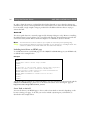
Easy - AXIS IP Installer
7.a Windows 95/98 & NT - Install the AXIS
IP Installer. You will find the installation
program on the AXIS Online CD and on
the Axis Web Site at http://www.axis.com
7.b Run the AXIS IP Installer from the Start
menu.
7.c Restart your camera server.
Quick - ARP/ping
7. Windows 95/98 & NT - Start a DOS
window and type these commands:
arp -s <camera IP address> <Ethernet address>
<my PC IP address>
ping <IP address>
Example
arp -s 192.168.3.191 00-40-8c-10-00-86
192.168.3.193
ping 192.168.3.191
UNIX & OS/2 - Type these commands:
arp -s <IP address> <Ethernet address> temp
ping <IP address>
Example
arp -s 192.168.3.191 00:40:8c:10:00:86 temp
ping 192.168.3.191
7.dLocate the serial number of your camera
server in the list.
7.e Enter the desired IP address, and click Set
IP address.
8. To access the camera server Home Page,
click Home page of selected Axis-server...
8. To access the camera server Home Page,
start your Web browser and enter the IP
address in the location/address field:
http://<IP address>/
Example
http://192.168.3.191/
9. Adjust the focus of the camera(s). Click Reload/Refresh in your Web browser to test your
adjustments.
The installation is complete and you can now include snapshots into your own applications.
Modem Only Installation
See Appendix C - Modem Installation on how to install your camera server if you are using a modem.
AXIS 200+ and 240 User’s Guide
2
About This Document
Liability
This guide is applicable for software releases 1.41 and 1.12 and
above for the AXIS 200+ and 240 Camera Servers respectively.
Every care has been taken in the preparation of this manual; if you
detect any inaccuracies or omissions, please inform your local Axis
office which can be found on the cover of this document. Axis
Communications AB cannot be held responsible for any technical or
typographical errors and reserves the right to make changes to the
product and manuals without prior notice. Axis Communications AB
makes no warranty of any kind with regard to the material contained
within this document, including, but not limited to, the implied
warranties of merchantability and fitness for a particular purpose.
Axis Communications AB shall not be liable nor responsible for
incidental or consequential damages in connection with the
furnishing, performance or use of this material.
The document provides introductory information as well as
instructions on how to set up and manage the camera server. It is
intended for anyone involved in installing and using the camera
server.
For more detailed instructions, refer to the User’s Manuals for
the AXIS 200+ and 240 that are available in on-line format at the
Axis Website and on the AXIS Online CD.
Safety Notices
Please observe all safety markings and instructions when using
this product.
Year 2000 Compliance
Caution!
Axis Communications AB warrants that the AXIS 200+ and 240 are
Year 2000 compliant.
Potential hazard that can damage the product.
Important!
Trademark Acknowledgments
Potential hazard that can seriously impair operation.
Acrobat, Adobe, Ethernet, IBM, Internet Explorer, LAN Manager,
Macintosh, Microsoft, Netscape Navigator, OS/2, UNIX, Windows,
WWW are registered trademarks of the respective holders.
Do not proceed beyond any of the above notices until you have
fully understood the implications.
Legal Considerations
Camera surveillance can be prohibited by laws that vary from
country to country. Check out the laws in your local region
before using the AXIS 200+ and 240 for surveillance.
Electromagnetic Compatibility (EMC)
USA - This equipment generates, uses, and can radiate radio
frequency energy and if not installed and used in accordance
with the instruction manual, may cause interference to radio
communications. It has been tested and found to comply with
the limits for a Class A computing device pursuant to Subpart B
of Part 15 of FCC rules, which are designed to provide
reasonable protection against such interference when operated in
a commercial environment. Operation of this equipment in a
residential area is likely to cause interference in which case the
user at his/her own expense will be required to take whatever
measures may be required to correct the interference. Shielded
cables should be used with this unit to ensure compliance with
the Class A limits.
Europe
- This digital equipment fulfils the
requirements for radiated emission according to limit B of
EN55022/1994, and the requirements for immunity according
to EN50082-1/1992 residential, commercial, and light industry.
AXIS COMMUNICATIONS
<Product
Name> Quick User’s Guide
Java and all Java-based trademarks and logos are trademarks or
registered trademarks of Sun Microsystems, Inc. in the United States
and other countries. Axis Communications AB is independent of Sun
Microsystems Inc.
Support Services
Should you require any technical assistance, please contact your local
dealer. If your questions cannot be answered immediately, your dealer
will forward your queries through the appropriate channels to ensure
you a rapid response.
If you are connected to Internet, you can obtain on-line manuals,
technical support, software updates, application software and general
corporate information from any of the locations listed below.
WWW:
http://www.axis.com
FTP:
ftp://ftp.axis.com/pub/axis
AXIS 200+ and 240 User’s Guide
Revision 1.0
Part No: 16500
Dated: January 1999
Copyright © Axis Communications AB,
1996 - 1999
AXIS 200+ and 240 User’s Guide
Table of Contents
3
Table of Contents
Product Overview . . . . . . . . . . . . . . . . . . . . . . . . . . . . . . . . . . . . . . . . . . . . . . . . . . . . . . . . . . 4
The AXIS 200+ and 240 Network Camera Servers . . . . . . . . . . . . . . . . . . . . . . . . . . . . . 4
The AXIS Online CD . . . . . . . . . . . . . . . . . . . . . . . . . . . . . . . . . . . . . . . . . . . . . . . . . . . . . . . 5
Installation Summary . . . . . . . . . . . . . . . . . . . . . . . . . . . . . . . . . . . . . . . . . . . . . . . . . . . . . . . . 6
Connecting the Hardware . . . . . . . . . . . . . . . . . . . . . . . . . . . . . . . . . . . . . . . . . . . . . . . . . . . . 6
Connecting the AXIS 200+ to a Mounting Assembly . . . . . . . . . . . . . . . . . . . . . . . . . . . .
Connecting Your Cameras to the AXIS 240 . . . . . . . . . . . . . . . . . . . . . . . . . . . . . . . . . . . .
Connecting the Camera Server to Your Network . . . . . . . . . . . . . . . . . . . . . . . . . . . . . . .
Assigning an IP Address . . . . . . . . . . . . . . . . . . . . . . . . . . . . . . . . . . . . . . . . . . . . . . . . . . . . . .
6
6
7
7
Using the AXIS IP Installer . . . . . . . . . . . . . . . . . . . . . . . . . . . . . . . . . . . . . . . . . . . . . . . . . . .
Using ARP in Windows 95/98 and Windows NT . . . . . . . . . . . . . . . . . . . . . . . . . . . . . . .
Using ARP in UNIX and OS/2 . . . . . . . . . . . . . . . . . . . . . . . . . . . . . . . . . . . . . . . . . . . . . . . .
Verifying the Installation . . . . . . . . . . . . . . . . . . . . . . . . . . . . . . . . . . . . . . . . . . . . . . . . . . . . . .
8
8
9
9
Adjusting the Focus . . . . . . . . . . . . . . . . . . . . . . . . . . . . . . . . . . . . . . . . . . . . . . . . . . . . . . . . 11
Configuring the Camera Server . . . . . . . . . . . . . . . . . . . . . . . . . . . . . . . . . . . . . . . . . . . . . . . 12
Using a Web Browser . . . . . . . . . . . . . . . . . . . . . . . . . . . . . . . . . . . . . . . . . . . . . . . . . . . . . 12
Using the Camera Server. . . . . . . . . . . . . . . . . . . . . . . . . . . . . . . . . . . . . . . . . . . . . . . . . . . . 12
Snapshots . . . . . . . . . . . . . . . . . . . . . . . . . . . . . . . . . . . . . . . . . . . . . . . . . . . . . . . . . . . . . . . .
Automatic Picture Updating . . . . . . . . . . . . . . . . . . . . . . . . . . . . . . . . . . . . . . . . . . . . . . . . .
Pan/Tilt Control . . . . . . . . . . . . . . . . . . . . . . . . . . . . . . . . . . . . . . . . . . . . . . . . . . . . . . . . . . .
External Web Sites . . . . . . . . . . . . . . . . . . . . . . . . . . . . . . . . . . . . . . . . . . . . . . . . . . . . . . . .
CRON Scripts . . . . . . . . . . . . . . . . . . . . . . . . . . . . . . . . . . . . . . . . . . . . . . . . . . . . . . . . . . . .
Application Examples . . . . . . . . . . . . . . . . . . . . . . . . . . . . . . . . . . . . . . . . . . . . . . . . . . . . . . .
13
15
18
19
19
24
Appendix A - Hardware Inventory . . . . . . . . . . . . . . . . . . . . . . . . . . . . . . . . . . . . . . . . . . . . 25
Connectors and Indicators . . . . . . . . . . . . . . . . . . . . . . . . . . . . . . . . . . . . . . . . . . . . . . . . . . 26
Appendix B - Auto Iris . . . . . . . . . . . . . . . . . . . . . . . . . . . . . . . . . . . . . . . . . . . . . . . . . . . . . . 29
General . . . . . . . . . . . . . . . . . . . . . . . . . . . . . . . . . . . . . . . . . . . . . . . . . . . . . . . . . . . . . . . . . .
Connecting an Auto Iris Lens to the AXIS 200+ . . . . . . . . . . . . . . . . . . . . . . . . . . . . . . .
Level Adjustment . . . . . . . . . . . . . . . . . . . . . . . . . . . . . . . . . . . . . . . . . . . . . . . . . . . . . . . . .
ALC Adjustment . . . . . . . . . . . . . . . . . . . . . . . . . . . . . . . . . . . . . . . . . . . . . . . . . . . . . . . . . .
Appendix C - Modem Installation . . . . . . . . . . . . . . . . . . . . . . . . . . . . . . . . . . . . . . . . . . . . .
29
29
30
30
31
Using the Camera Server without a Network . . . . . . . . . . . . . . . . . . . . . . . . . . . . . . . . . . 31
Setting the IP Address Using a Null Modem Cable . . . . . . . . . . . . . . . . . . . . . . . . . . . . . 37
Index . . . . . . . . . . . . . . . . . . . . . . . . . . . . . . . . . . . . . . . . . . . . . . . . . . . . . . . . . . . . . . . . . . . . 38
4
Product Overview
AXIS 200+ and 240 User’s Guide
Product Overview
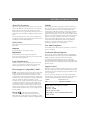
The AXIS 200+ and 240 Network Camera Servers
With built-in Web servers, the AXIS 200+ and 240 offer easy and cost-effective solutions for
interactive surveillance and remote monitoring. Connected directly to Ethernet networks, they
provide a source for live color pictures over the network or even over the Internet.
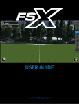
AXIS 200+
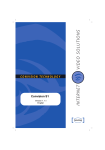
AXIS 240
The AXIS 200+ is a self-contained network camera with interchangeable optics.
The AXIS 240 is a small, high performance camera server that can service up to four PAL/NTSC
video source and one S-video camera.
Caution!
The CCD (charged coupled device) within the AXIS 200+ can become permanently damaged if the
camera lens is exposed to too much direct sunlight or halogen light! If this is the case use an Auto Iris
Lens. See Appendix B - Auto Iris for more information.
AXIS 200+ and 240 User’s Guide
Product Overview
The AXIS Online CD
The AXIS Online CD provides an easy-to-use electronic catalogue, that includes all of the latest
AXIS product software, utilities software, white papers, user documents, technical references etc.
It can be used within all of the supported Axis computing environments.
Startup Procedures for Windows
The AXIS Online CD will autostart from a local CD drive on Windows 95/98 and NT platforms.
Windows 3.x users should navigate to the CD using File Manager and click the setup31.exe file.
Startup Procedures for Macintosh, UNIX and OS/2
Navigate to the CD root directory and click on the start.pdf file from within your preferred file
manager application.
Note: If the Adobe Acrobat Reader 3.0 is not installed on your system, locate and run the appropriate
installer from the tools/Acrobat/ folder. Refer to the readme.txt file for full path name details.
HTML Interface
You can access a Web browser interface to the contents of the AXIS Online CD by clicking the
HTML button from within the main installation dialog. This interface allows Network
Administrators to distribute the CD contents over the intranet by simply broadcasting a URL
reference.
5
6
Installation Summary
AXIS 200+ and 240 User’s Guide
Installation Summary
You install your camera server in these steps:
• Connecting the hardware
• Assigning an IP address
• Verifying the installation
• Configuring the camera server
• Adjusting the focus
Connecting the Hardware
Connecting the AXIS 200+ to a Mounting Assembly
Fasten the camera server to the supplied mounting assembly and
position it appropriately for your application.
Note:The AXIS 200+ can be mounted on any standard mount.
Tip!
To make the camera stand smaller, remove the middle part of the
mounting assembly. The camera holder can now be attached
directly to the foot. See the illustration.
Caution!
The CCD (charged coupled device) within the AXIS 200+ can become permanently damaged if the
camera lens is exposed to too much direct sunlight, or halogen light! If this is the case, please use an
Auto Iris Lens. See Appendix B - Auto Iris for more information.
If used outdoors or in extreme environments, the camera server must be housed in an outdoor
casing. For more information, please refer to the camera sever product pages at http//www.axis.com/
Connecting Your Cameras to the AXIS 240
Connect the cameras to the AXIS 240 using the appropriate cables/connectors. The AXIS 240 can
service up to four coax/BNC cameras and one S-video camera.
It is possible to connect a Pan/Tilt device to the RS-232 Pan/Tilt port of the AXIS 240 for remote
adjustment of the camera position. The AXIS 240 can control one Pan/Tilt device at a time, or
several if they are daisy chained. Refer to the Pan/Tilt Control information provided in the User’s
Manual and/or your camera supplier’s documentation for further details on connecting the
cameras.
AXIS 200+ and 240 User’s Guide
Assigning an IP Address
Connecting the Camera Server to Your Network
1. Note the serial number of your camera server for future reference during the installation
procedure. This is located on the underside label of the camera server.
2. Connect your camera server to the network using an Ethernet 10baseT connector.
3. Connect the power supply to the camera server.
4. Check that the Power indicator is constantly lit.
Assigning an IP Address
To enable access to your camera server you must first assign it an appropriate IP address.
Before You Begin
Make sure the camera server is powered up and attached to the network.
IP Address - Acquire an unused IP address from your Network Administrator.
System Privileges - You need root privileges on your UNIX system and administrator
privileges on the Windows NT servers.
Ethernet Address - Depending on the method you are using, you will need to know the
Ethernet address of your camera server. The Ethernet address is based on the serial number found
on the underside label of the unit.
Important!
Do not use the default or example IP address when installing your camera server. Always consult your
Network Administrator before assigning an IP address.
Set the IP address using one of these methods, depending on your network environment:
Method
Network environments
See ...
AXIS IP Installer
Windows 95/98 & Windows NT
“Using the AXIS IP Installer” on page 8
ARP
Windows 95/98 & Windows NT
“Using ARP in Windows 95/98 and Windows NT” on page 8
UNIX, OS/2
“Using ARP in UNIX and OS/2” on page 9
BOOTP
UNIX
Refer to the User’s Manual.
RARP
UNIX
7
8
Assigning an IP Address
AXIS 200+ and 240 User’s Guide
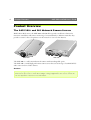
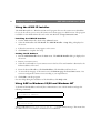
Using the AXIS IP Installer
The AXIS IP Installer is a Windows 95/98 & NT program that sets the camera server IP address
for you. It also allows you to access the camera server home page via a Web browser. The program
is available on the AXIS Online CD and on the Axis Web Site at http://www.axis.com/
Installing the AXIS IP Installer
1. On the AXIS Online CD, click on the Software button.
2. Select the IP Installer and click Install. The AXIS IP Installer - Setup dialog is displayed on
the screen.
3. Follow the instructions as they appear on the screen.
4. Click Finish to complete the setup.
Setting the IP Address
1. Run the AXIS IP Installer from the Start menu. The AXIS IP Installer dialog is displayed on
the screen.
2. Restart your camera server.
3. Select the serial number of your camera server in the list. The serial number is identical to the
Ethernet address of the unit.
4. Enter the desired IP address. Click Set IP address. The IP address will now be set.
5. To access the home page of the camera server, click Home page of selected Axis-server... You
can now configure the camera server according to your requirements.
6. Click OK to exit the program.
For more help during the installation of the IP address, click Help or F1.
Using ARP in Windows 95/98 and Windows NT
To download the IP address and verify the communication, start a DOS window and type the
following commands:
arp -s <camera IP address> <Ethernet address>
ping <camera IP address>
Example:
arp -s 192.16.253.80 00-40-8c-10-00-86
ping 192.16.253.80
The host will return ‘Reply from 192.16.253.80 ...’ or some similar message. This means that
the address has been set and the communication is established.
AXIS 200+ and 240 User’s Guide
Verifying the Installation
Important!
Windows 95 only: When using the Windows 95 implementation of ARP, change the first line to:
arp -s <camera IP address> <Ethernet address> <w95host IP address>, where <w95host IP address> is the IP
address of your Windows 95 host.
Example:
arp -s 192.16.253.80 00-40-8c-10-00-86 192.16.253.81
ping 192.16.253.80
Note: When you execute the ping command for the first time, you will experience a significantly longer
response time than usual.
Using ARP in UNIX and OS/2
To download the IP address and verify the communication, type the following commands:
arp -s <camera IP address> <Ethernet address> temp
ping <camera IP address>
Example:
arp -s 192.16.253.80 00:40:8c:10:00:86 temp
ping 192.16.253.80
The host will return ‘192.16.253.80 is alive’, or some similar message to indicate that the
address has been set and the communication is established.
Note: When you execute the ping command for the first time, you may experience a significantly longer
response time than usual.
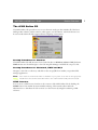
Verifying the Installation
After assigning an IP address, verify the connection between your camera server and the network.
1. Start your Web browser and enter the name or IP address in the location/address field:
Example
http://cameraserv/
or:
http://192.16.253.80/
9
10
Verifying the Installation
AXIS 200+ and 240 User’s Guide
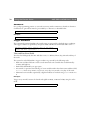
2. The Home Page of your camera server showing a snapshot just taken is displayed:
3. To further test your camera server, take some more snapshots. Simply click Reload/Refresh in
your Web browser to do that.
Note: Web pages are kept locally for fast browsing, and your browser may occasionally display a cached
image as opposed to a newly taken snapshot. When this happens, simply click Reload/Refresh in
your Web browser. Some browsers may even force you to clear the cache, or use forced reload,
e.g. Shift+Reload in Netscape.
Using the Server Push and ActiveX Links
Click Server push from the Server push page to start automatic picture updating using Netscape
Navigator. Click ActiveX to enable automatic picture updating using Microsoft Internet Explorer.
Notes: The AXIS Camera Control software is pre-requisite for automatic picture updating using
Microsoft Internet Explorer, and must be installed on your client prior to enabling ActiveX. This
software is available on the AXIS Online CD and via the Axis Website.
See also, Automatic Picture Updating, on page 15.
AXIS 200+ and 240 User’s Guide
Adjusting the Focus
Adjusting the Focus
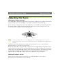
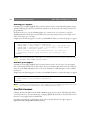
AXIS 200+ Camera Server
Your AXIS 200+ is delivered in approximate focus position, with focus set to infinity. The lens has
rotational focus control. To fine adjust to close focus, carefully turn the smaller lens.
If you cannot get a sharp picture, screw the smaller lens to its end and loosen the lock ring. Direct
the camera towards a distant object and bring the camera into focus by turning the entire lens
mount. Remember to tighten the lock ring afterwards.
Lens
Lock ring
Lens mount
Note: The lens assembly rotates on a screw fitting and can be completely removed. If you need to
remove the lens, take care not to let any dust enter the lens as this will effect the quality of your
snapshots.
Check the result of the adjustments by taking some new pictures. Use one of the automatic
updating functions to monitor the focus changes.
Because the AXIS 200+ is designed with a CS-mount, the lens supplied with your product can be
replaced with any standard CS lens, typically used within the surveillance industry. A C-mount lens
will also work with the AXIS 200+ Camera Server if used with an adaptor that effectively provides
a spacer with two female 1-32 threads and moves a lens 5mm farther from the camera. See
Appendix B or the AXIS 200+ Camera Server User’s Manual for more information.
AXIS 240 Camera Server
Adjust the focus of the camera(s) connected to your AXIS 240. Refer to your camera
documentation for information on how to do this.
11
12
Configuring the Camera Server
AXIS 200+ and 240 User’s Guide
Configuring the Camera Server
You can configure the camera server via hyperlinks from its own web pages using any standard Web
browser. Alternatively, you can configure the camera server using FTP. See the User’s Manual for
more information on how to do this.
Note: For the latest technical information, refer to the camera server Website at
http://www.axis.com/products/camera_servers/
Using a Web Browser
To configure the camera server, enter the name or IP address into the location/address field of your
Web browser, as detailed below:
Example
http://192.16.253.80/
On the AXIS 200+ and 240 Home Pages, click on the Settings link to reach the Configuration
pages. Log on as user root and use the default password pass. In the Configuration pages you can
change all unit parameters, including the password.
Notes: It is recommended that you change the password of your camera server as all Axis products are
shipped with the same password as default.
For optimized performance, it is additionally recommended that all unused video inputs are
disabled from the AXIS 240 Configuration - Video page.
Using the Camera Server
After installing the AXIS 200+ and 240 and assigning an appropriate IP address, you are ready to
use the camera server in your own applications.
This section describes how to use the AXIS 200+ and 240 effectively to realize its full potential,
including:
• Snapshots - Taking snapshots of various formats and including them on your web pages.
• Automatic picture updating - Various methods for continuously updating images are available,
including, Server push, Java image feed and Refresh image feed functions.
• Pan/Tilt control - Supports input/ouput operations via the HTTP protocol - applicable to the
AXIS 240 only.
• External Web sites - Using snapshot files on the Internet.
• CRON scripts - Triggering the camera server by times or input events.
Further information on how to use your camera server is provided in the User’s Manual.
AXIS 200+ and 240 User’s Guide
Using the Camera Server
Snapshots
Throughout this user guide, an image generated by the camera server is referred to as a snapshot.
The following information describes how to take a snapshot and also defines the various types of
snapshots files that can be produced.
Taking Snapshots
For each snapshot taken, the camera server generates a JPEG file and stores it within its internal
memory.
Home Page Snapshots
To produce a snapshot within the AXIS 200+ and 240 Home Pages, simply enter the name or IP
address of the unit into the location/address field of your Web browser:
Example
http://192.16.253.80/
This causes the camera server to generate a fullsize JPEG image. Each time you reload the page, a
new snapshot is displayed within the camera server Home Pages.
Clean Snapshots
To generate clean snapshots that are not embedded within the camera server Home Page, you must
specify the preferred snapshot type for the target JPEG file within the URL of your Web browser.
Snapshots can be created in different sizes, e.g. fullsize, halfsize etc.
Example
http://192.16.253.80/fullsize.jpg
http://192.16.253.80/halfsize.jpg
Snapshot Types
You can adjust the size and appearance of your snapshots, ranging from small, highly compressed
to large, high-quality images.
The file size depends on several factors. Low compression and large images result in larger files, but
higher quality. Images with a lot of detail will also generate larger files.
13
14
Using the Camera Server
AXIS 200+ and 240 User’s Guide
These image files are available within your AXIS 200+ and 240.
File name
Description
fullsize.jpg
The standard resolution. Hardware generated in about. 0.5 seconds.
halfsize.jpg
Excellent for thumbnails. Hardware generated in about 0.3 seconds.
lastshot.jpg
The last snapshot taken, either a ‘fullsize’ or ‘halfsize’ snapshot. Primarily
intended for software applications for archiving a buffered image.
hugesize.jpg
The highest resolution snapshot available. As opposed to the ‘fullsize’ and
‘halfsize’ images, the ‘hugesize’ image is software generated which takes
about 10 seconds.
zoom.jpg
A cutout from the center of ’hugesize’. It takes about 8 seconds to
generate.
Including Snapshots in Web Pages
Follow these steps to integrate live snapshots into your own web pages:
1. Create your web page using your preferred HTML creation tool, i.e. an ordinary text editor, or
a dedicated HTML design application.
2. In your Web browser, enter the name or IP address of your camera server together with the
preferred snapshot type.
Example
http://192.16.253.80/fullsize.jpg
3. Add an HTML reference to the snapshot within the target web page.
Example
<HTML>
<HEAD>
<TITLE>Sample page</TITLE>
</HEAD>
<BODY>
<H1>Welcome to Axis Web Camera Demo</H1>
<IMG ALT="Fullsize JPEG Image”
SRC=”http://192.16.253.80/fullsize.jpg">
</BODY>
</HTML>
Each time anyone visits this page, a new fullsize snapshot will be generated and displayed in
the Web browser. Since Web pages are kept locally for fast browsing, your browser may sometimes display a cached image as opposed to a newly taken snapshot. When this happens, simply
click Reload/Refresh in your Web browser.
You can easily change the size of your snapshot.
AXIS 200+ and 240 User’s Guide
Using the Camera Server
Example
<HTML>
<HEAD>
<TITLE>Axis Camera Server Page</TITLE>
</HEAD>
<BODY>
<H1>Welcome to the enlarged Axis Web Camera Demo</H1>
<IMG ALT="Fullsize JPEG Image”
SRC=”http://192.16.253.80/fullsize.jpg"
WIDTH="704" HEIGHT="576">
</BODY>
</HTML>
In this example the width of the image has been doubled from normal fullsize 352 to 704 pixels and the height from normal (PAL) fullsize 288 to 576 pixels.
Automatic Picture Updating
The camera server supports several methods for automatic picture updating:
• Server push
• ActiveX
• HTML refresh image feed
• CamImg Java applet
• CamCtrl Java applet (includes Pan/Tilt control for the AXIS 240)
Server Push
The Server push function continuously pushes new snapshots to your Web browser.
Example
<HTML>
<HEAD>
<TITLE>Axis Camera Server Page</TITLE>
</HEAD>
<BODY>
<H1>Welcome to the Server Push Demo</H1>
<IMG
SRC=”http://192.16.253.80/cgi-bin/fullsize.srvpushb"
</BODY>
</HTML>
The frame rate depends on how fast the AXIS 200+ and 240 can deliver the snapshot data over the
available network bandwidth. Therefore, you cannot adjust the frequency of the Server push
snapshots within your Web browser.
15
16
Using the Camera Server
AXIS 200+ and 240 User’s Guide
In order to limit the memory overhead that this facility demands, no more than five clients can
simultaneously activate a Server push link to the same camera server. Once this client threshold has
been exceeded, a single snapshot image is produced for all additional clients that are trying to
activate the link.
ActiveX
The Server push function is currently supported by Netscape Navigator only. However, installing
the AXIS Camera Control software onto your client and using the ActiveX function provides the
same functionality within Microsoft Internet Explorer on a Windows 95/98 or NT PC.
Note: The AXIS Camera Control software is pre-requisite for automatic picture updating using
Microsoft Internet Explorer, and must be installed on your client prior to enabling ActiveX. This
software is available on the AXIS Online CD and via the Axis Website.
Including ActiveX into an HTML page
To include ActiveX into an HTML page, use the OBJECT and PARAM tags in your HTML code,
as defined in the example below.
Example
<HTML>
<HEAD>
<TITLE>Axis Camera Server Page</TITLE>
</HEAD>
<BODY>
<H1>Welcome to the ActiveX Camera Server Demo page</H1>
<OBJECT ID=”Axis Camera” WIDTH=352 HEIGHT=288
CLASSID=”CLSID:1773DB27-C4D2-11D1-87CE-00805FD85E14”>
<PARAM NAME=”AutoSize” VALUE=1>
<PARAM NAME=”CamAddress” VALUE=”192.16.253.80”
<OBJECT>
</BODY>
</HTML>
192.16.253.80 is an example of a camera IP address. For more information about ActiveX and the
OBJECT and PARAM tags, please refer to the Network Camera Severs Developers’ pages at
http://www.axis.com/products/camera_servers/
Server Push or ActiveX?
You can also direct your HTML page to choose either Server Push or ActiveX, depending on the
browser viewing your page. To do this you need to include a JavaScript in your html file, as
described in the example below.
AXIS 200+ and 240 User’s Guide
Using the Camera Server
Example
<HTML>
<HEAD>
<TITLE>Choose the right browser</TITLE>
</HEAD>
<BODY>
<SCRIPT LANGUAGE=”JavaScript”>
if (navigator.appName == “Microsoft Internet Explorer”)
{ document.write(“<OBJECT ID=Axis Camera
CLASSID=CLSID:1773DB27-C4D2-11D1-87CE-00805FD85E14>”);
document.write(“<PARAM NAME=CamAddress VALUE=192.16.253.80>”);
document.write(“<PARAM NAME=AutoSize VALUE=0>”);
document.write(“<BR>Download the <B> Axis ActiveX Camera
Control</B><BR>from the <B>Server push page. <B></OBJECT>”);
}
else {document.write(“<IMG
SRC=http://192.16.253.80/cgi-bin/fullsize.srvpushb>”);
}
</SCRIPT>
</BODY>
</HTML>
HTML Refresh Image Feed
This function instructs your Web browser to collect a new snapshot at an adjustable rate. It is
supported by most standard Web browsers.
Notes: To terminate automatic picture updating, you can click Stop or enter another URL.
The Java script code example detailed below, is used to bypass browser image caching.
Example
<HTML>
<HEAD>
<META http-equiv=”Refresh” content=”5”>
<TITLE>Refresh image feed</TITLE>
</HEAD>
<BODY>
<SCRIPT LANGUAGE=”JavaScript”>
day = new Date()
document.write(“<IMG SRC=\”http://192.16.253.80/fullsize.jpg?dummy=”);
document.write(day.getHours());
document.write(day.getMinutes());
document.write(day.getSeconds());
document.write(“\”>”);
</SCRIPT>
</BODY>
</HTML>
17
18
Using the Camera Server
AXIS 200+ and 240 User’s Guide
CamImg Java Applet
CamImg is a Java applet supplied with your Axis Camera Server. It automatically updates images
(default=fullsize.jpg) and can be started from anywhere on the network. The image refresh rate is
programmable.
Should you choose to use the CamImg applet on a remote server, it is necessary to copy the
CamImg.class file and all other associated files from your Axis Camera Server to the target server
where your images are to be kept.
Simply insert the following piece of code in your HTML file where you want the images to appear.
<APPLET CODEBASE="http://www.yoursite.com/classes/"
CODE="CamImg.class" WIDTH=362 HEIGHT=328>
<PARAM NAME = "Image" VALUE = "/img/image1.jpg | /img/image2.jpg">
<PARAM NAME = "ImageLabel" VALUE = "First image | Second image">
<PARAM NAME = "Interval" VALUE = "5">
<HR>If you were using a Java-enabled browser, you would see a
continuously updating image instead of this paragraph. <HR>
</APPLET>
Note: The CamImg parameters defined above are optional. Please refer to the User Manual for a full
description of the available parameter options.
CamCtrl Java Applet
CamImg is a Java applet supplied with your Axis Camera Server. It is an easy-to-use Java applet
that continuously loads live from Axis Camera Servers and enables Pan/Tilt control of connected
cameras via the AXIS 240. Please refer to the User’s Manual for a full description of the available
parameters.
Simply insert the following piece of code in your HTML file where you want the images to appear
<APPLET CODEBASE="http://192.16.253.80/classes/"
CODE="CamCtrl.class" WIDTH=512 HEIGHT=478>
</APPLET>
Note: A number of optional parameters can be included into your CamCtrl applet. Please refer to the
User’s Manual for a full description of the available parameter options.
Pan/Tilt Control
Clicking the Pan Tilt link from the AXIS 240 Home page activates a Pan/Tilt facility that allows
connected cameras to be controlled using a simple graphical Web interface. The Pan/Tilt Control
function is only supported in the AXIS 240.
For further information on this facility, please refer to the Pan/Tilt/Zoom support pages at
http://www.axis.com/products/camera_servers/
AXIS 200+ and 240 User’s Guide
Using the Camera Server
External Web Sites
If your Website is not adversely effected by heavy traffic, and your camera server is connected
directly to an Ethernet network, it is possible to fetch images directly from the camera server.
However, it is recommended that images are accessed over an assisting Web server and not directly,
when:
• modem connected,
• located behind a firewall,
• subject to high volume traffic,
• used for generating large files, such as hugesize.jpg which is very time consuming.
If any of the above circumstances prevail, the best way to transfer images from the camera server to
an assisting Web server, is to use CRON scripts.
Note: You can use the CRON script facility to collect snapshots periodically.
CRON Scripts
Embedded within your Axis camera server is a time/event based scripting language, CRON. This
service allows you to program event and/or time triggered functions within the camera server.
Any of the following tools can be used for generating a CRON script file:
• The Online Editor. An easy-to-use on-line editor available via the Cron Script - Cron Configuration pages.
• TheText Editor. An integrated text editor available via the Cron Script - Cron Configuration
pages.
• CRON Script Maker. Fully documented CRON applications available in a form-format from
the Network Camera Servers Developers’ pages at http://www.axis.com/ Each form includes a
CRON Script Maker containing several interactive fields for generating custom CRON scripts.
• Any common text editor. Edit using any common text editor and download the file using FTP.
Script Format
A CRON script can include one or several entries. Each entry includes the following elements:
• Comment(s)
• A trigger condition
• Command(s)
• An entry termination character %
Note: Only one CRON script can be resident within the camera server at a time.
19
20
Using the Camera Server
AXIS 200+ and 240 User’s Guide
Comments
It is good programming practice to start each new entry with a comment to describe its function.
Comments are optional but must be proceeded by a # character, as detailed below:
# <comment>
Example:
# This cron entry will...
Trigger Condition
The commands contained within each specific entry are triggered by a defined trigger condition.
The trigger condition is specified by six separate fields and must be terminated with a colon “:”.
<Minute> <Hour> <Day> <Month> <Day of the week>
<Input and Boot (optional)> :
Time and Date Event Fields
The first five fields specify the time and date events, i.e. Minute, Hour, Day, Month and Day of
the week.
The syntax for each field within a trigger condition is governed by the following rules:
• Each time and date field can contain several numerical event variables that are delimited by
commas and hyphens.
• Each field is delimited by an open space.
• An asterisk (*) represents the full range of event variables within the relative time and date field,
i.e. * * * * * means every minute, every hour, every day, every month, every day of the week.
• Numerical event variables separated by a hyphen indicates an inclusive range, i.e. 2-6 means 2 to
6.
Example:
Trigger every month, between the fourth and eighth at 10.03, 12.03 and 14.03, using the 24 hr
clock:
3 10,12,14 4-8 * * :
AXIS 200+ and 240 User’s Guide
Using the Camera Server
Input and Boot Field
The sixth field is an optional Input and Boot field that defines the input and boot trigger functions.
You can program the AXIS 200+ and 240 to trigger at startup or on the logical states present on the
Control button and digital input ports, using the trigger variables boot, B, I1 and I2
respectively. The B, I1 and I2 trigger variables must be proceeded by an activate condition, /, \, 0
or 1, to indicate when the trigger variable is activated.
Note: The AXIS 240 has input por ts 1 - 4.
The table below outlines the available trigger variables and their possible combinations:
Trigger Variable
Description
boot
Activate at startup.
\B
Activate after high-low logical transition of Control button.
/B
Activate after low-high logical transition of Control button.
1B
Activate when Control button is logically high (pressed).
0B
Activate when Control button is logically low (released).
\I1
Activate after high-low logical transition on Input Port 1.
/I2
Activate after low-high logical transition on Input Port 2.
1I1
Activate when Input Port 1 is logically high.
0I2
Activate when Input Port 2 is logically low.
... etc.
Note: The camera server polls the input por ts every 0.2 seconds. Thus, more rapid logical transitions
will not be detected.
By conjugating the trigger variables using a logical AND function (&), you can develop complex
triggering mechanisms.
Example 1
Activate on Control button transition from high to low and Input port 1 high.
\B&1I1
Example 2
Activate on Input port 1 low and Input port 2 transition from low to high.
0I1&/I2
21
22
Using the Camera Server
AXIS 200+ and 240 User’s Guide
CRON Commands
Several CRON script commands can be used within an entry. All commands must be terminated
with a semi-colon “;”.
This table lists the available commands:
Command
Description
alert
Sends a small message to a remote host.
buffer_init
Initiates an image buffer.
buffer_start
Stores snapshots in the image buffer.
buffer_stop
Ends the storing of snapshots in the image buffer.
ftp
Transfers an image to a remote host using FTP.
log
Writes a message to the camera server log file
mail
Sends an e-mail using SMTP.
offline
Terminates the current PPP connection.
online
Dials up a modem for PPP connection.
ptz - applies
to 240 only
Pans, tilts and zooms connected video cameras.
reset
Restarts the unit.
sleep
Makes a pause in the CRON script execution.
snapshot
Updates the last snapshot image.
Notes: Although the downloaded entries are effectively executed in parallel, the commands included
within each entry are executed sequentially, i.e. the second command is not executed until the
first is finished.
The Help pages accessible via the camera server Web interface describe CRON command
syntax in detail.
Sample CRON Scripts
Example 1
The following script will:
1. Execute every 10 minutes during daylight (5 AM - 9 PM).
2. Take a snapshot of the fullsize.jpg image and store it internally in the camera as lastshot.jpg.
3. Dial up over a modem and connect to an Internet Service Provider (ISP).
Note: The ISP dialed in this example supports CHAP login and does not require a script part. An
example of the on-line command to an ISP that requires a log on script could be:
online -dial 1234567 -user "USER" -pass "PASS" -timeout m6s40 -script
"'' 'ogin:' '$(USER)' 'assword:' '$(PASS)'"
4. After log on we send the image taken previously to an ftp server. It is first stored with the
temporary name tmp.jpg and later renamed to image followed by the year, month, day, hour, minute
and second. An example filename would be image1998-11-23_08_34_00.jpg
AXIS 200+ and 240 User’s Guide
Using the Camera Server
5. Disconnect from the ISP..
# Dial to an ISP:
0,10,20,30,40,50 5-21 1-31 1-12 1-12 0-6:
snapshot fullsize.jpg;
online -dial 1234567 -user “USER” -pass “PASS” -timeout m2;
ftp -host 207.242.7.186 -user ftpuser -pass PASS -src lastshot.jpg
-dest images$Y-$n-$d_$h_$m_$s.jpg -temp tmp.jpg;
offline;
%
Example 2 (AXIS 240 only)
When executing the following script, a PTZ (Pan/Tilt/Zoom) camera is moved to a predefined
position. While the camera is moving, the script pauses for several seconds until it is certain that the
camera has reached the desired position. A snapshot is taken and sent via ftp to a server. The
camera then moves to the next position and a new snapshot is taken and sent. In this example, this
procedure is repeated every hour.
# This is an example of an Axis extended CRON script:
0 0-23 1-31 1-12 0-6:
ptz -preset 1;
sleep 5;
ftp -host 207.242.7.186 -user USER -pass PASS -src fullsize.jpg
-dest myDestinationFile1.jpg -cam 1;
ptz -preset 2;
sleep 5;
ftp -host 207.242.7.186 -user USER -pass PASS -src fullsize.jpg
-dest myDestinationFile2.jpg -cam 1;
%
23
24
Application Examples
AXIS 200+ and 240 User’s Guide
Example 3
At start-up a buffer for 10 fullsize images from camera 1 is created, and a process to continually fill
this buffer is initiated. A state change of logic state from 0 to 1 at digital input 1, causes five more
snapshots to be added to the buffer. The process is then stopped. At this time, the buffer holds five
snapshots taken before the event, and five snapshots taken after the event. These snapshots are then
sent to the designated e-mail address. The process to fill the buffer is then started again.
# This is an example of an Axis extended CRON script:
0-59 0-23 1-31 1-12 0-6 BOOT:
buffer_init 1,2,10;
buffer_start -src fullsize.jpg -duration inf;
%
0-59 0-23 1-31 1-12 0-6 \I1 :
buffer_stop -src fullsize.jpg -store 5;
mail -s “A subject” -a images/buffer.jpg -t [email protected]
-b fullsize.jpg -n 10;
buffer_start -src fullsize.jpg -duration inf;
%
Application Examples
The application possibilities are unlimited. Security professionals use the AXIS 240 for general
surveillance, monitoring of medical equipment, industrial production flows, conference rooms,
parking facilities and badge recognition.
Axis Camera Servers empower you to monitor operations remotely from within the comfort of
your own home, headquarters, or indeed from any workstation of your choosing that supports a
Web browser. Just think... no more late trips to the factory to investigate problems!
The only real limitation for the number of applications to which the AXIS 240 can be suited is
your fantasy.
Tip!
For interesting application ideas, visit the Network Camera Servers Developer’s Pages at our
Website http://www.axis.com/
AXIS 200+ and 240 User’s Guide
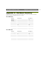
Appendix A - Hardware Inventory
Appendix A - Hardware Inventory
Unpack and check all the items against the check list below. Contact your dealer if anything is
missing or damaged. All packing material is recyclable.
The AXIS 200+
Hardware
Model Variants
Part Numbers
Camera Server
AXIS 200+
0064-2
15104
Mounting
Assembly
Europe
14233
UK
14234
Australia
14255
USA
14253
Japan
14254
Extension Cord
10 feet (3 m)
15187
Media
Title
Part Numbers
CD-ROM
AXIS Online CD
-
Printed Material
This User’s Guide
16500
Power Supply
The AXIS 240
Hardware
Model Variants
Part Numbers
Camera Server
AXIS 240
0072-1
Power Supply
Europe
14233
UK
14234
Australia
14255
USA
14253
Japan
14254
Media
Title
Part Numbers
CD-ROM
AXIS Online CD
-
Printed Materials
This User’s Guide
16500
25
26
Appendix A - Hardware Inventory
AXIS 200+ and 240 User’s Guide
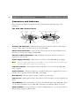
Connectors and Indicators
This information provides a useful reference when performing the remaining stages of the
installation.
The AXIS 200+ Camera Server
Control
button
Snapshot
indicator
Camera lens
Lock ring Serial number
Power supply Ethernet RS-232 serial Auxiliary I/O
10baseT connector
CS ring
Power Net
indicator indicator
Auxiliary I/O Connector - A Mini-DIN 8-pole external connector with two alarm inputs,
one relay output and an Auto-Iris connector for the AXIS 200+.
RS-232 Serial Connector - A 9 pin D-sub connector provides the physical RS-232 serial
interface to a modem server within the AXIS 200+.
Ethernet 10BaseT Connector - 10BaseT (RJ-45) twisted pair Ethernet connector for
connection to the network.
Power Supply Connector - Jack socket for connection of the AXIS 200+ power supply.
Note: The power supply supplied with your AXIS 200+ is country specific. Please check that the type
of power supply you are using is correct. See page 25.
Snapshot Indicator - The Snapshot indicator will flash on every occasion the AXIS 200+
takes a snapshot.
Power Indicator - The Power indicator is normally lit while power is applied. If it is not lit, or
it flashes, there is problem with the AXIS 200+ power supply.
Net Indicator - The Net indicator flashes to indicate network activity.
Camera Lens - Wide angle lens with rotational-focus control. Possible to mount standard C/CS
lenses.
Serial Number - The serial number is located on the underside label of the AXIS 200+. Please
note that the serial number of your AXIS 200+ is identical to the Ethernet address of the unit.
Control Button - The Control button is used for multiple purposes, e.g. restoring the factory
default settings, triggering CRON scripts.
AXIS 200+ and 240 User’s Guide
Appendix A - Hardware Inventory
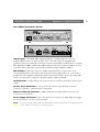
The AXIS 240 Camera Server
Video Inputs - The AXIS 240 is equipped with four coax/BNC video-in connectors
(CAM1-CAM4) and one S-video connector (Y/C). The video inputs are equipped with
signal autosensing to provide full connectivity to cameras using different video formats, e.g. NTSC,
PAL, Black/white 50Hz or Black/white 60Hz. Physical connections made using RG59, 75 ohm
coax cable Video Cable, have a recommended maximum length of 800 feet (250 m).
DIP Switches - Each video input is normally terminated with a 75 ohm resistor via an
associated DIP switch, connected in the down-position. If the AXIS 240 is to be connected in
parallel with other equipment, disable the input termination by turning the corresponding DIP
switch to the up-position. Otherwise, the picture quality might be reduced.
I/O Connector - A Mini-DIN 8-pole external connector with four alarm inputs and one relay
output.
RS-232 Serial Connectors - Two 9 pin D-sub connectors providing RS-232 serial
connection, typically to a Pan/Tilt device and modem.
Ethernet 10BaseT Connector - 10BaseT (RJ-45) twisted pair Ethernet connector for
connection to the network.
Power Supply Connector - Jack socket (PS-D) for connection of AXIS 240 power supply.
An alternative power connector is also provided.
Note: The power supply supplied with your AXIS 240 is country specific. Please check that the type of
power supply you are using is correct. See page 25.
27
28
Appendix A - Hardware Inventory
AXIS 200+ and 240 User’s Guide
Active Indicator - The Active indicator flashes on every occasion one of the connected
cameras takes a snapshot.
Power Indicator - The Power indicator is normally lit while power is applied. If it is not lit, or
it flashes, there is problem with the AXIS 240 power supply.
Network Indicator - The Network indicator flashes to indicate network activity.
Control Button - The Control button is used for multiple purposes, e.g. restoring the factory
default settings, triggering CRON scripts.
Serial Number - The serial number is located on the underside label of the AXIS 240. Please
note that the serial number of your AXIS 240 is identical to the Ethernet address of the unit.
AXIS 200+ and 240 User’s Guide
Appendix B -Auto Iris
Appendix B - Auto Iris
General
The CCD (charged coupled device) supplied with the AXIS 200+ can become permanently
damaged if the camera lens is exposed to too much direct sunlight or halogen light. In extreme and
outdoor environments such as these, it recommended that the AXIS 200+ is fitted with an Auto Iris
lens. An Auto Iris lens also improves image quality during high and low light conditions.
The AXIS 200+ is designed with a CS-mount which means that the lens supplied with your
product can be replaced with any standard CS lens, typically used within the surveillance industry.
Notes: A C-mount lens will also work with the AXIS 200+ Camera Server if used with an adaptor that
effectively provides a spacer with two female 1-32 threads and moves a lens 5mm farther from
the camera.
DC type lenses are not supported. Use an Auto Iris type lens.
An Auto Iris lens can be distinguished from a DC-type lens by the LEVEL and ALC adjustment
screws. These screws are not fitted to DC-type lenses. An Auto Iris lens additionally uses the
video signal as feedback to the lens.
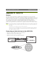
Connecting an Auto Iris Lens to the AXIS 200+
• Red wire connects to PIN # 5 power source 12 V DC (+)
• White wire connects to pin # 3 video signal
• Black wire connects to pin # 8 ground for lens power
29
30
Appendix B -Auto Iris
AXIS 200+ and 240 User’s Guide
Level Adjustment
It is very important that you make the following adjustments in the brightest light condition
(bright sun light) that you intend to use the AXIS 200+.
1. Close the lens completely by turning the LEVEL screw head towards low position. The image
on your screen should now be black.
2. Carefully turn the LEVEL screw head towards high position until the image appears on the
screen. The lens is now adjusted to protect the CCD sensor against being damaged by bright
sun light.
ALC Adjustment
The ALC has been adjusted by the manufacturer and may not need to be adjusted for general use.
With the ALC screw head you adjust the photometry between peak and average. See the lens
documentation for more information.
Refer to the AXIS 200+ User’s Manual for further information on fitting an Auto Iris lens to the
AXIS 200+.
AXIS 200+ and 240 User’s Guide
Appendix C -Modem Installation
Appendix C - Modem Installation
Using the Camera Server without a Network
The RS-232 port of your Axis Camera Server can be used to communicate with the camera server,
using an ordinary modem, an ISDN modem, a CDPD modem or a direct serial connection to a
computer.
We will in this chapter describe how to connect your camera server to a standard modem and how
to dial from a modem connected Microsoft Windows 95 PC, to your modem connected Axis
Camera Server.
The Axis Camera Server has “plug-and-play” functionality for a few selected modems. We suggest
you use one of the modems listed below since it makes installation and setup so much easier.
•
•
•
•
•
•
•
•
•
USRobotics Courier 33600
USRobotics Sportster 33600
USRobotics Sportster Flash
USRobotics Sportster MessagePlus
USRobotics Sportster 28800
USRobotics Sportster Voice 56k
USRobotics 33600 Fax
3Com Impact IQ External ISDN Modem
Diamond SupraExpress 56e
Notes: Although most external modems are known to work well with Axis’ Camera Servers, only the
modems listed above have been fully tested by Axis Communications.
Modems not featured in the above list will normally require the setting of a modem specific initiation string. Modem initialization takes place when the camera server starts up, during which the
following parameters must be set:
1 - Flow control must be set to hardware flow control.
2 - Echo mode, all commands should be echoed.
3 - All replies from the modem must be in ASCII form.
31
32
Appendix C -Modem Installation
AXIS 200+ and 240 User’s Guide
Connecting Your Modem:
1. Connect modem to phone line.
2. Connect your modem to the RS-232 modem port on your camera server.
3. Connect your modem to Power and power up your modem.
4. Restart your Axis Camera Server.
If the modem you are using is one of the “plug and play” modems you should now be able to dial
from a PC to your camera server and connect.
Note: the default IP number of your camera server is 192.36.253.80.
Changing the Modem Baud Rate
After successfully connecting to your camera server from a PC (as described in Configuring the
Dial-Up Adapter, on page 33), you can now increase the baud rate of your modem. To do this,
follow the instructions below:
1. From the Home page of your Axis Camera Server, click Settings.
2. Log on as root (default password is pass).
3. Click the Serial port/Modem button (AXIS 200+/AXIS 240) to go to the modem page and
modify the baud rate so that it is compatible with your modem. The new port speed will take
effect next time you restart your Axis Camera server.
Notes: The maximum baud rate for the Axis 200+ Camera Server is 38400bps and 115200bps for the
Axis 240 Camera Server.
More information regarding CDPD and GSM modems is available on the Axis web site at
http://www.axis.com/
AXIS 200+ and 240 User’s Guide
Appendix C -Modem Installation
Configuring the Dial-Up Adapter
The following instructions describe how to set up a Microsoft Windows 95B PC for modem
dial-up connection to an Axis Camera Server. Deviations from these instructions can be expected
when using other operating systems.
It is assumed that the TCP/IP, dial-up networking, modem and serial port configurations are
correctly installed. If this is not the case, please consult your Windows 95 documentation and
install these before configuring the dial-up adapter for access to your Axis Camera Server.
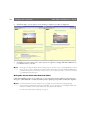
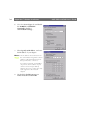
1. From the Control Panel, double click
the Network icon and highlight your
Dial-Up Adapter. Click Properties.
2. Go to the Advanced tab. Select Use IPX
header compression from the Property:
list, and enter the value No in the Value:
drop down list. Click OK.
3. Double click My Computer on your
desktop and double click the Dial-Up
Networking icon.
4. Right click Make New Connection.
Select Properties.
5. Enter the phone number to which your
Axis Camera Server is connected.
33
34
Appendix C -Modem Installation
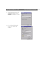
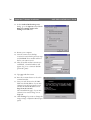
6. Go to the Server Types tab and disable
the NetBEUI and IPX/SPX
Compatible checkbox.
Click TCP/IP Settings...
7. Select Specify an IP address, and enter
the IP address of your adapter.
Notes: The IP address selected must be on
the same Network segment as the IP
address of the Axis Camera Server
that you intend to connect to.
If you have a network card installed
on your PC, the IP address of your
camera server and your dial-up
adapter can not be on the same network segment as the network
adapter.
8. Uncheck Use default gateway on
remote network and click OK.
AXIS 200+ and 240 User’s Guide
AXIS 200+ and 240 User’s Guide
9. In My Connection dialog, go to the
Scripting tab and disable the start
terminal screen minimized checkbox.
Click OK.
10. Go to the General tab. From the
Connect using... dialog, click
Configure...
Appendix C -Modem Installation
35
36
Appendix C -Modem Installation
11. In the Standard Modem Properties
dialog, go to the Options tab and check
Bring up terminal window after
dialing. Click OK twice.
12. Restart your computer.
13. Start the camera server dial-up
connection created in the previous steps
and click Dial. Your modem will now
dial to your camera server.
14. After successful modem connection is
established, a terminal window will
appear. Log on as a root user (default
password is pass.)
15. Type ppp and then return.
16. Press the continue button to close the
terminal window.
17. Start your web browser. In the URL
field enter the IP address of your Axis
Camera Server (If your camera server
still has the default IP address enter:
http://192.36.253.80/).
The internal Home page of your Axis
Camera Server and an image is now
displayed.
18. Click Settings if you want to change the
image settings or adjust the RS-232 port
speed.
AXIS 200+ and 240 User’s Guide
AXIS 200+ and 240 User’s Guide
Appendix C -Modem Installation
Setting the IP Address Using a Null Modem Cable
The IP address of the camera server can be changed directly via direct serial connection, using a
Null Modem cable and an appropriate terminal program. The instructions provided below are
relevant to Microsoft’s HyperTerminal.
Connecting the Camera Server
1. Attach the null modem cable to the RS-232 connector of the camera server and the serial port
of your computer.
2. From the Windows Start Menu, start the HyperTerminal program.
3. Create a new connection description by selecting a name and icon. Click OK.
4. The Select To dialog is displayed. Select Direct to Com1 from the drop-down Connect using
menu. Click OK.
5. Configure the Port details as follows:
Connect using: Direct to Com1
Port Settings: bits per second=9600, data bits=8, parity=none,
stopbits=1, flow control=hardware
6. If you wish to retain the Port Settings for future use, save the connection description to your
hard drive.
7. Click OK to initiate the HyperTerminal session and wait approximately 30 seconds to allow for
the link to become established.
8. Type CLIENT at the command prompt (Note that HyperTerminal Commands are case
sensitive).
9. At the Login prompt, type the login name and password of the camera server (default to root
and pass respectively).
10. Type ip at the command prompt to check the current IP address:
11. You can change the IP address by typing the following:
set_ip <camera IP address>
Example:
set_ip 192.16.253.80
Note: It is not possible to have more than one concurrent HyperTerminal session running on the client.
37
38
Index
AXIS 200+ and 240 User’s Guide
Index
A
ActiveX 10, 16
Application examples 24
ARP 7, 8, 9
Auto Iris 29
AXIS IP Installer 7
AXIS Online CD 5
B
BOOTP 7
C
CamCtrl Java applet 18
Camera lens
AXIS 200+ 26
CamImg applet 18
CCD 4, 29
Configuring 12
Connectors
AXIS 200+ 26
AXIS 240 27
CRON
Commands 22
Input and Boot 20, 21
Online Editor 19
Script format 19
Text Editor 19
Time and Date 20
Trigger 20
D
DIP switches 27
E
Ethernet address 7
F
Focus 11
H
Home page 10
HTML refresh image feed 17
http
//www.axis.com/ 24
I
Indicators
AXIS 200+ 26
AXIS 240 28
Inventory 25
IP address 7
L
Lens
ALC adjustment 29, 30
C-mount 11, 29
CS-mount 11, 29
DC-type 29
LEVEL adjustment 29, 30
M
Modem
ASCII 31
Baud Rate 32
CDPD 31
Dial-Up Adapter 33
GSM 32
Initialization 31
ISDN 31
RS-232 31
Mounting assembly 6, 25
O
OBJECT tags 16
Optics 4
OS/2 9
P
Pan/Tilt 6, 18
PARAM tags 16
Ping command 9
Power supply 25
PTZ 23
R
RARP 7
Refresh image feed 17
Reload/Refresh 10
RS-232 6, 37
S
Serial number
AXIS 200+ 26
AXIS 240 28
Server push 10, 15
Snapshots 13
U
UNIX 9
URL 13
V
Video inputs 27