1
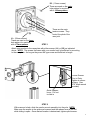
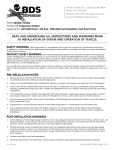
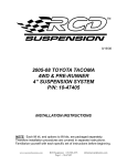
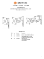
FPP1M0
FPP1M1
FPP1M2
VESA MOUNTS LOW PROFILE, SINGLE ARM AND DUAL ARM
Assembly Instructions
Hardware List
Ref. Qty.
Part No.
AA
12
030-0845
BB
12
030-1234
CC
1/2
012-0760
DD
1/2
012-0815
Description
M4 x 0.7 , 20mm Phillips Pan Screws
M4 x 0.7 , 12mm Phillips Pan Screws
Cable Clips (Beam)
(1) for FPP1M1 & (2) for FPP1M2
(No Cable Clip is used on FPP1M0)
Cable Clip (Pole)
(1) for FPP1M0 & FPP1M1
(2) for FPP1M2
1
BB - (12mm screws)
These are used on the outer
hole pattern for monitors
with a 100mm pattern.
AA - (20mm screws)
These are used on the inner
hole pattern for monitors
with a 75mm pattern.
These are the main
tension screws. They
control the pitch of the
vesa joint.
STEP 1
Attach your monitor to the vesa plate with either screws (AA) or (BB) as indicated
above. NOTE: The screws that came with your monitor may be sufficient for mounting
to the vesa plate. As long as they are a M4 type screw and sufficient in length.
Loosen Screws
Prior to Entry.
Tighten to secure
in place. (Use
3/16” Allen wrench
provided)
Quick Release
Lever - Pull out
to slide in
STEP 2
With someone’s help, slide the monitor mount assembly into the pole. NOTE:
Make sure the screws in the spike are loosened and the release lever is pull out
while sliding in spike. Once desired location is determined, tighten spike screws.
2
NOTE: 2 different sets of plastic clips are
provided for the best possible fit.
Fold plastic cable
clip closed.
Knuckle joints are preset to correct
tension. No adjustments are needed.
Power cords
Feed power cords through clips. Then snap clips
into beam’s bottom slots and pole’s slot as shown.
Part # 031-7675
Rev. 08.28.07 CZ
4