1
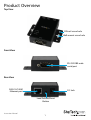
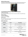
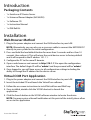
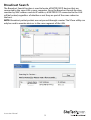
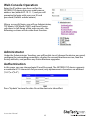
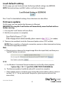
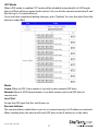
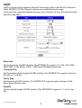
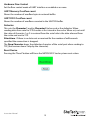
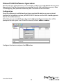
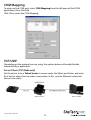
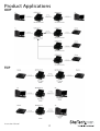
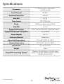
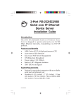
1 Port RS232 Serial over IP Ethernet
Device Server
NETRS2321P
*actual product may vary from photos
DE: Bedienungsanleitung - de.startech.com
FR: Guide de l'utilisateur - fr.startech.com
ES: Guía del usuario - es.startech.com
IT: Guida per l'uso - it.startech.com
NL: Gebruiksaanwijzing - nl.startech.com
PT: Guia do usuário - pt.startech.com
For the most up-to-date information, please visit: www.startech.com
Manual Revision: 07/09/2013
FCC Compliance Statement
This equipment has been tested and found to comply with the limits for a Class B digital
device, pursuant to part 15 of the FCC Rules. These limits are designed to provide reasonable
protection against harmful interference in a residential installation. This equipment generates,
uses and can radiate radio frequency energy and, if not installed and used in accordance with
the instructions, may cause harmful interference to radio communications. However, there
is no guarantee that interference will not occur in a particular installation. If this equipment
does cause harmful interference to radio or television reception, which can be determined by
turning the equipment off and on, the user is encouraged to try to correct the interference by
one or more of the following measures:
• Reorient or relocate the receiving antenna.
• Increase the separation between the equipment and receiver.
• Connect the equipment into an outlet on a circuit different from that to which the receiver
is connected.
• Consult the dealer or an experienced radio/TV technician for help.
Use of Trademarks, Registered Trademarks, and other Protected Names and Symbols
This manual may make reference to trademarks, registered trademarks, and other
protected names and/or symbols of third-party companies not related in any way to
StarTech.com. Where they occur these references are for illustrative purposes only and do not
represent an endorsement of a product or service by StarTech.com, or an endorsement of the
product(s) to which this manual applies by the third-party company in question. Regardless
of any direct acknowledgement elsewhere in the body of this document, StarTech.com hereby
acknowledges that all trademarks, registered trademarks, service marks, and other protected
names and/or symbols contained in this manual and related documents are the property of
their respective holders.
Instruction Manual
Table of Contents
Product Overview...................................................................................1
DIN Rail Mounting..................................................................................................................................... 2
Load Default Settings / System Reset Button.................................................................................. 2
LED Indicators............................................................................................................................................. 2
RJ45 Ethernet Pin Assignments............................................................................................................ 3
RS-232 DB9 Male Pin Assignment........................................................................................................ 3
Introduction.............................................................................................4
Packaging Contents.................................................................................................................................. 4
Installation...............................................................................................4
Web Browser Method............................................................................................................................... 4
Virtual COM Port Application................................................................................................................ 4
Broadcast Search........................................................................................................................................ 5
Web Console Operation........................................................................................................................... 6
Administrator............................................................................................................................................... 6
Authentication............................................................................................................................................ 6
System IP....................................................................................................................................................... 7
System Status.............................................................................................................................................. 7
Load default setting.................................................................................................................................. 8
Firmware update........................................................................................................................................ 8
TCP Mode...................................................................................................................................................... 9
Telnet Server / Client................................................................................................................................. 9
UART............................................................................................................................................................... 12
Virtual COM Software Operation.......................................................................................................... 14
COM Mapping............................................................................................................................................. 15
TCP/UDP........................................................................................................................................................ 15
Instruction Manual
i
Product Applications..............................................................................17
UDP................................................................................................................................................................. 17
TCP................................................................................................................................................................... 17
Specifications...........................................................................................18
Technical Support...................................................................................19
Warranty Information.............................................................................19
Instruction Manual
ii
Product Overview
Top View
DIN rail screw hole
Wall-mount screw hole
Front View
RS-232 DB9 male
serial port
Rear View
RJ45 10/100M
Ethernet port
DC Jack
Load Default/Reset
Button
Instruction Manual
1
DIN Rail Mounting
Attach the included DIN Rail brackets (one per side) using the provided screws to the
top DIN Rail screw hole (marked in the above diagram), and clip to your DIN Rail
Load Default Settings / System Reset Button
Load Default Settings
Press and hold this button for more than 3 seconds, then release to load the factory
default settings.
IP address: 10.1.1.1
Subnet Mask: 255.0.0.0
Login ID / Password: admin
System Reset
Press and hold this button for more than 10 seconds, then release to reboot the device
(maintains configuration settings)
LED Indicators
LED Name
Ready
Link/Act
Status
Description
On
Power is on and the device is ready.
Off
Power is off or the device is not ready.
On
UTP is link.
Blinking
UTP Tx/Rx is activity.
Off
UTP is not link.
Blinking
RS-232 port is transmitting or receiving
data.
Off
No data is transmitting or receiving in
RS-232 port.
Tx/Rx
Instruction Manual
2
RJ45 Ethernet Pin Assignments
Pin
1
TX+
2
TX-
3
RX+
6
RX-
RS-232 DB9 Male Pin Assignment
NOTE: This serial device server performs as a DTE device.
Pin
Name
I/O
1
DCD
Input
2
RD
Input
3
TD
Output
4
DTR
5
Output
GND
6
DSR
Input
7
RTS
Output
8
CTS
Input
Instruction Manual
3
Introduction
Packaging Contents
• 1 x Serial over IP Device Server
• 1 x Universal Power Adapter (NA/UK/EU)
• 1 x Software CD
• 1 x Instruction Manual
• 1 x DIN Rail Kit
Installation
Web Browser Method
1. Plug in the power adapter and connect the RJ45 interface to your LAN.
NOTE: Alternatively, you can also use a crossover cable to connect the NETRS2321P
directly to your system for the initial configuration.
2. Press and hold the load default button for more than 3 seconds and less than 10
seconds, then release it. This will return the serial device server to factory default
and it will respond to the IP address 10.1.1.1.
3. Configure the PC to the same IP domain.
4. Open a web browser and connect to http://10.1.1.1 to open the configuration
interface. The default login ID will be “admin” and the password will be “admin”.
5. Once logged in, you will have access to all configuration settings including the
ability to change the IP address for the device server.
Virtual COM Port Application
1. Plug in the power adapter and connect the RJ45 interface to your LAN.
2. Insert the included CD and launch the VirtualCom software.
3. Follow the on-screen instructions to install VirtualCom and WinPcap.
4. Once installed, double-click the VCOM shortcut to launch the
application.
5. Click the Search button in the VCOM software window to locate the device.
NOTE: You may receive a firewall notification at this point of the install, please allow
access to this application
Instruction Manual
4
Broadcast Search
The Broadcast Search function is used to locate all NETRS2321P devices that are
connected to the same LAN as your computer. Since the Broadcast Search function
searches by MAC address and not IP address, all NETRS2321P connected to the LAN
will be located, regardless of whether or not they are part of the same subnet as
the host.
NOTE: Broadcast packet packets are not passed through a router. The VCom utility can
only be used to monitor devices in the same segment of the LAN.
NETRS2321P
Instruction Manual
5
Web Console Operation
Enter the IP address you have set for the
NETRS2321P device into your web browser
address bar (default IP: 10.1.1.1) and you will
prompted to login with your user ID and
password (Default: admin/admin).
After a successful login, you will see Administrator,
TCP Mode, UDP Mode, UART, and Reset Device
selections in left frame of the web console - the
following sections will describe their function.
Administrator
Under the ‘Administrator’ heading, you will be able to set/change the device password,
configure the networking parameters, display the current firmware version, load the
factory defaults, and perform any future firmware upgrades.
Authentication
In this page, you can change login ID and Password. The NETRS2321P device supports
a maximum of 15 characters for password, only alphanumeric characters are allowed
(“0-9”,”a-z”,”A-Z”).
Press “Update” to store the data. Reset the device to take effect.
Instruction Manual
6
System IP
On this page, you can adjust the NETRS2321P network configuration. If set to DHCP
mode, all other settings will be ignored, and the IP address will be assigned by DHCP
server after resetting the device.
Press “Update” to store the data. Reset the device to take effect.
System Status
On this page, you can display the system Kernel firmware version and MAC Address.
You can also adjust the device alias (Target Name) and Idle timeout settings. The Target
Name field allows a Max of 12 characters, including “0-9”,”a-z”,”A-Z”,”_” (underscore),and
“-” (dash).
NETRS2321P
Press “Update” to store the ‘Target Name’ data, and then, NETRS2321P will reset to
take effect.
Instruction Manual
7
Load default setting
On this page, you can load and store the factory default settings into EEPROM.
NOTE: Network settings and MAC address will not be changed.
Press “Load” to load default settings. Reset the device to take effect.
Firmware update
On this page, you can update the firmware via Ethernet.
WARNING! Pressing the ‘Load’ button will immediately erase the flash with no
further warning
1. Pressing the “Load” button will erase flash.
2. Wait for erase process to complete.
3. There are two methods to do the Firmware Update action (TFTP or Web):
NOTE: Please avoid loss of network connection, power or other interruption during
the firmware upgrade procedure
Web
a. Please type in or browse the target image file in the input field, and then press
“update” button to continue.
TFTP
a. Use Windows Command Prompt window to run the tftp client program.
Syntax: tftp -i 10.1.1.1 put FILE_DIRECTORY\FILENAME.bin
b. The firmware update should take about 45 seconds to complete.
c. If the update process somehow goes wrong (like power failure), please connect
to http://10.1.1.1 to try and restart the process (you may have to reset the
device first)
Instruction Manual
8
TCP Mode
NOTE: When TCP mode is set to Server or Client mode, the UDP mode will be
disabled automatically. When UDP mode is enabled, the TCP mode will be disabled
automatically.
Once you have completed making changes, press "Update" to store the data. Reset the
device to take effect.
Telnet Server / Client
Set the device to be a Telnet Server. In server mode, the Telnet port listens and waits
for a host or other client to make a connection. In this case the Ethernet connected
device is the client.
Set the device to be a Telnet Client. In the case the Ethernet connected device is the
Telnet server or other NETRS2321P in server mode.
Instruction Manual
9
Reverse Telnet
Reverse Telnet works the same as Telnet Server mode. The Telnet port is listens for
a connection after booting up. If you encounter errors when using some Telnet
clients, such as the Microsoft interpretation of Telnet for Windows XP you can try the
connection using Reverse Telnet mode.
CLI Mode
The Command Line Interface (CLI) allows user to configure and control NETRS2321P
directly through the UART interface.
NOTE: CLI mode is only available when NETRS2321P is in TCP Server Mode.
Port Number
This assigns the TCP server port number that the server will listen on for connecting
clients. (Only for TCP Server Mode)
Remote Server IP Address
When in Client mode, this device will automatically try to connect to the remote TCP
server with this IP address.
Client mode inactive timeout
When in Client mode, this parameter sets the time that device will maintain a
connection until timeout, if there is no data transfer over the connection. After
disconnecting, the device will try to build a new connection again immediately.
Server mode protect timeout
When in Server mode, this parameter sets the time that device will maintain a
connection until timeout, if there is no data transfer over the connection. Once
disconnected, only a Client can initiate a new connection to the Server.
Instruction Manual
10
UDP Mode
When UDP mode is enabled, TCP mode will be disabled automatically. In UDP mode,
the Local Port will be assigned to this device. You can list the remote connection IP and
Port for up to 10 remote devices.
Once you have completed making changes, press "Update" to store the data. Reset the
device to take effect.
Mode
Listen: When in UDP Listen mode, it can only receive remote UDP data.
Normal: When in UDP Normal mode, it can both receive and send UDP data to
remote units.
Local Port
Assign the UDP port that this unit listens on.
Remote Address
The remote address table allows users to set several remote site IP addresses and ports.
When sending data, the device will send UDP data to the IP addresses in the table.
Instruction Manual
11
UART
UART or Universal Asynchronous Receiver Transmitter refers to the ‘RS-232 serial port’
of the NETRS2321P. All of the port settings are modified from this page.
Once you have completed making changes, press "Update" to store the data. Reset the
device to take effect.
Baud rate
Set the baud rate of UART interface. The NETRS2321P supports 110, 300, 1200, 2400,
4800, 9600, 19200, 38400, 57600, 115200 and 230400bps baud rates.
Character Bits
Set the number of data length of UART interface. The NETRS2321P supports character
bits of 5, 6, 7, or 8 bits.
Parity Type
Set the parity of UART interface. The NETRS2321P supports parity settings of Odd,
Even, Space, Mark or none.
Stop Bit
Set the stop bit length of UART interface. The NETRS2321P supports 1, 1.5 or 2 stop
bits.
Instruction Manual
12
Hardware Flow Control
Set the flow control mode of UART interface as enabled or as none.
UART Memory Overflow count
Shows the number of overflow bytes in network buffer.
UART FIFO Overflow count
Shows the number of overflows counted in the UART RX buffer.
Delimiter
This sets the Character 1 and/or Character 2 to be used as the delimiter. When
sending data from serial to TCP the data is first stored in the cache. When set, not until
the value of character 1 or 2 is received from the serial side is the data released from
the cache and sent to TCP.
Silent time - If there is no data sent or received for the number of milliseconds
specified the connection is dropped.
The Drop Character drops the delimiter character of the serial port when sending to
TCP, (the receiver doesn't display the character).
Reset Device
Pressing the “Reset” button will force the NETRS2321P to do system reset action.
Instruction Manual
13
Virtual COM Software Operation
The Virtual Com application lets you install and configure your NETRS2321P easily over
the network. Five function groups are provided to ease the installation process, allow
COM mapping, and provide monitoring and IP location server functions.
Configuration
Once the software is installed and you have searched the device on your network
(outlined in Installation section), all NETRS2321P devices on the LAN should appear in
the list of available devices.
Select the one you would like to adjust and click the Configure button. You will be
prompted to enter your User ID and Password (Default: admin / admin)
Configure the device and press the OK button
Instruction Manual
14
COM Mapping
To map a virtual COM port, select COM Mapping from the left pane of the VCOM
application, then click Add
Click OK to create the COM Mapping
TCP/UDP
Depending on the protocol you are using, the options below will enable/disable
automatically as applicable.
Server/Client (TCP Mode only)
Set the device to be a Telnet Server. In server mode, the Telnet port listens and waits
for a host or other client to make a connection. In this case the Ethernet connected
device is the client.
Instruction Manual
15
Set the device to be a Telnet Client. In the case the Ethernet connected device is the
Telnet server or other NETRS2321P in server mode.
IP Address
Depending on your selections above, there are one of three scenarios:
TCP Server - Disabled
TCP Client - Remote Server Address
UDP - Remote Target Address
Local Port
Assigns the local port for the device to listen on
TCP Server – Assigns the TCP server port number that the server will listen on
TCP Client – Disabled
UDP – Assign the UDP port that this unit listens on
COM
Assign the desired virtual COM port number
Remote Port
TCP Server – Disabled
TCP Client – Assign the remote TCP port you wish to communicate on
UDP – Assign the remote UDP port you wish to communicate on
Enable Control Connection (TCP Server or Client Only)
Enables/Disables control of the serial device on a remote network. Using the IP
address and port number allows the user to gain control of the receiver from a remote
location when this is enabled.
Second(s) for reconnection interval
Dictates the duration that the software will automatically attempt to reconnect the
COM port to the serial port on the serial device server, for the purpose of keeping the
connection alive.
Instruction Manual
16
Product Applications
UDP
TCP
TCP Server
Mode
Instruction Manual
17
Specifications
1x DB-9 (9-pin; D-Sub) Male
1x RJ-45 Female
Connectors
Serial Protocol
RS-232
Maximum Baud Rate
230400
Data Bits
5,6,7,8
Flow Control
RTS/CTS, None
Parity
Odd, Even, None, Space, Mark
Stop Bits
1, 1.5, 2
Supported Protocols
DHCP, TCP/IP, UDP, HTTP, ICMP, ARP, Telnet
Supported Network Link Speeds
10/100 Mbps
Power Adapter
12V, 1A
Enclosure Material
Aluminum
Operating Temperature
0°C to 60°C (32°F to 140°F)
Storage Temperature
-10°C to 70°C (14°F to 158°F)
Dimensions
81 x 53 x 23 mm
Weight
295g
Compatible Operating Systems
Windows® 8 (32/64-bit), 7 (32/64), Vista
(32/64), XP (32/64), 2000 Windows® Server
2008 R2, 2003 (32/64)
Instruction Manual
18
Technical Support
StarTech.com’s lifetime technical support is an integral part of our commitment to
provide industry-leading solutions. If you ever need help with your product, visit
www.startech.com/support and access our comprehensive selection of online tools,
documentation, and downloads.
For the latest drivers/software, please visit www.startech.com/downloads
Warranty Information
This product is backed by a two year warranty.
In addition, StarTech.com warrants its products against defects in materials
and workmanship for the periods noted, following the initial date of purchase.
During this period, the products may be returned for repair, or replacement with
equivalent products at our discretion. The warranty covers parts and labor costs only.
StarTech.com does not warrant its products from defects or damages arising from
misuse, abuse, alteration, or normal wear and tear.
Limitation of Liability
In no event shall the liability of StarTech.com Ltd. and StarTech.com USA LLP (or their
officers, directors, employees or agents) for any damages (whether direct or indirect,
special, punitive, incidental, consequential, or otherwise), loss of profits, loss of business,
or any pecuniary loss, arising out of or related to the use of the product exceed the
actual price paid for the product. Some states do not allow the exclusion or limitation
of incidental or consequential damages. If such laws apply, the limitations or exclusions
contained in this statement may not apply to you.
Instruction Manual
19
Hard-to-find made easy. At StarTech.com, that isn’t a slogan. It’s a promise.
StarTech.com is your one-stop source for every connectivity part you need. From
the latest technology to legacy products — and all the parts that bridge the old and
new — we can help you find the parts that connect your solutions.
We make it easy to locate the parts, and we quickly deliver them wherever they need
to go. Just talk to one of our tech advisors or visit our website. You’ll be connected to
the products you need in no time.
Visit www.startech.com for complete information on all StarTech.com products and
to access exclusive resources and time-saving tools.
StarTech.com is an ISO 9001 Registered manufacturer of connectivity and technology
parts. StarTech.com was founded in 1985 and has operations in the United States,
Canada, the United Kingdom and Taiwan servicing a worldwide market.