1
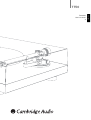
Turntable
User’s manual
2
ENGLISH
T T50
Contents
Introduction
Introduction .................................................................................................2
Thank you for purchasing this Cambridge Audio TT50 turntable. We
hope that you will enjoy many years of listening pleasure from it.
Limited warranty..........................................................................................3
Safety precautions ......................................................................................3
Important safety instructions ....................................................................4
Assembly/setup ..........................................................................................5
Cartridge downforce adjustment ............................................................6
Anti-skating (bias)adjustment .................................................................6
TT50 features ..............................................................................................7
Top view ....................................................................................................7
The TT50 has been jointly developed between Cambridge Audio and
Pro-Ject and features several parts unique to this model such as a
proprietary arm with non contact magnetic anti-skate. Other features
include a Cambridge Audio made acrylic platter, coated with a layer of
elastomer paint for careful control of resonance and matched acoustic
impedance to the vinyl record for maximum detail retrieval.
The isolation type feet also control resonance and provide a measure of
feedback resistance to vibration. The TT50 turntable is supplied with an
Audio Technica AT95E Moving Magnet cartridge fully aligned and setup
at the factory.
The TT50 should always be mounted on a good quality level support,
preferably one designed for use with turntables.
Rear view ..................................................................................................7
Operating instructions ................................................................................8
Playing records.........................................................................................8
Changing replay speed............................................................................8
Maintenance and cleaning.........................................................................8
Cartridge replacement/adjustment...........................................................8
Cartridge fitting ........................................................................................8
Cartridge alignment.................................................................................9
Your turntable can only be as good as the system it is connected to.
Please do not compromise on your supports, amplification, speakers or
cabling. Naturally we particularly recommend models from the
Cambridge Audio Azur range which have been designed to the same
exacting standards as this turntable. In particular pay attention to the
quality of your phono stage. The Cambridge Audio Azur 540P or 640P
models for instance are an excellent match for the TT50. Your dealer
can also supply excellent quality Cambridge Audio interconnects to
ensure your system realises its full potential.
Thank you for taking the time to read this manual; we do recommend
you keep it for future reference.
Adjusting the azimuth ...........................................................................10
Technical specifications ...........................................................................11
Troubleshooting.........................................................................................11
Cartridge alignment protractor ................................................................11
Matthew Bramble,
Cambridge Audio Technical Director
and the Turntable design team.
Visit www.cambridge-audio.com and register to receive notification of future
hardware and software releases.
This guide is designed to make installing and using this product as easy as
possible. Information in this document has been carefully checked for accuracy at
the time of printing; however, Cambridge Audio's policy is one of continuous
improvement, therefore design and specifications are subject to change without
prior notice. If you notice any errors please feel free to email us at:
[email protected]
This document contains proprietary information protected by copyright. All rights
are reserved. No part of this manual may be reproduced by any mechanical,
electronic or other means, in any form, without prior written permission of the
manufacturer. All trademarks and registered trademarks are the property of their
respective owners.
© Copyright Cambridge Audio Ltd 2007
2
Limited warranty
Safety precautions
Cambridge Audio warrants this product to be free from defects in
materials and workmanship (subject to the terms set forth below).
Cambridge Audio will repair or replace (at Cambridge Audio's option) this
product or any defective parts in this product. Warranty periods may vary
from country to country. If in doubt consult your dealer and ensure that
you retain proof of purchase.
Checking the Power Supply Rating
To obtain warranty service, please contact the Cambridge Audio authorised
dealer from which you purchased this product. If your dealer is not
equipped to perform the repair of your Cambridge Audio product, it can be
returned by your dealer to Cambridge Audio or an authorised Cambridge
Audio service agent. You will need to ship this product in either its original
packaging or packaging affording an equal degree of protection.
Proof of purchase in the form of a bill of sale or receipted invoice, which
is evidence that this product is within the warranty period, must be
presented to obtain warranty service.
This Warranty is invalid if (a) the factory-applied serial number has been
altered or removed from this product or (b) this product was not
purchased from a Cambridge Audio authorised dealer. You may call
Cambridge Audio or your local country Cambridge Audio distributor to
confirm that you have an unaltered serial number and/or you purchased
from a Cambridge Audio authorised dealer.
This Warranty does not cover cosmetic damage or damage due to acts of
God, accident, misuse, abuse, negligence, commercial use, or modification
of, or to any part of, the product. This Warranty does not cover damage due
to improper operation, maintenance or installation, or attempted repair by
anyone other than Cambridge Audio or a Cambridge Audio dealer, or
authorised service agent which is authorised to do Cambridge Audio
warranty work. Any unauthorised repairs will void this Warranty. This
Warranty does not cover products sold AS IS or WITH ALL FAULTS.
REPAIRS OR REPLACEMENTS AS PROVIDED UNDER THIS WARRANTY ARE
THE EXCLUSIVE REMEDY OF THE CONSUMER. CAMBRIDGE AUDIO SHALL
NOT BE LIABLE FOR ANY INCIDENTAL OR CONSEQUENTIAL DAMAGES FOR
BREACH OF ANY EXPRESS OR IMPLIED WARRANTY IN THIS PRODUCT.
EXCEPT TO THE EXTENT PROHIBITED BY LAW, THIS WARRANTY IS EXCLUSIVE
AND IN LIEU OF ALL OTHER EXPRESS AND IMPLIED WARRANTIES
WHATSOEVER INCLUDING, BUT NOT LIMITED TO, THE WARRANTY OF
MERCHANTABILITY AND FITNESS FOR A PRACTICAL PURPOSE.
Some countries and US states do not allow the exclusion or limitation of
incidental or consequential damages or implied warranties so the above
exclusions may not apply to you. This Warranty gives you specific legal
rights, and you may have other statutory rights, which vary from state to
state or country to country.
For your own safety please read the following instructions carefully
before attempting to connect this unit to the mains.
Check that the power supply unit indicates the correct supply voltage. If
your mains supply voltage is different, consult your dealer.
This unit is designed to operate only on the supply voltage and type that
is indicated on the power supply unit. Connecting to other power sources
may damage the unit.
This equipment must be switched off when not in use. To reduce the risk
of electric shock, do not disassemble any part of the unit. There are no
user serviceable parts inside. Refer servicing to qualified service
personnel.
The lightning flash with the arrowhead symbol within an
equilateral triangle is intended to alert the user to the
presence of un-insulated ‘dangerous voltage’ within the
product’s enclosure that may be of sufficient magnitude
to constitute a risk of electric shock to persons.
The exclamation point within an equilateral triangle is intended
to alert the user to the presence of important operating and
maintenance instructions in the service literature relevant to
this appliance.
The crossed-out wheeled bin is the European Union symbol
for indicating separate collection for electrical and electronic
equipment. This product contains electrical and electronic
equipment which should be reused, recycled or recovered
and should not be disposed of with unsorted regular waste.
Please return the unit or contact the authorised dealer from
whom you purchased this product for more information.
Approvals
This product complies with European Low Voltage
(73/23/EEC) and Electromagnetic Compatibility
(89/336/EEC) Directives when used and installed
according to this instruction manual. For continued
compliance only Cambridge Audio accessories should be used with this
product and servicing must be referred to qualified service personnel.
NOTE: THE MANUFACTURER IS NOT RESPONSIBLE FOR ANY RADIO OR
TV INTERFERENCE CAUSED BY UNAUTHORIZED MODIFICATIONS TO
THIS EQUIPMENT. SUCH MODIFICATIONS COULD VOID THE USER
AUTHORITY TO OPERATE THE EQUIPMENT.
This equipment has been tested and found to comply with the limits for
a Class B digital device, pursuant to Part 15 of the FCC Rules. These
limits are designed to provide reasonable protection against harmful
interference in a residential installation. This equipment generates,
uses and can radiate radio frequency energy and, if not installed and
used in accordance with the instructions, may cause harmful
interference to radio communications. However, there is no guarantee
that interference will not occur in a particular installation.
If this equipment does cause harmful interference to radio or television
reception, which can be determined by turning the equipment off and
on, the user is encouraged to try to correct the interference by one or
more of the following measures:
- Re-orient or relocate the receiving antenna.
- Increase the separation between the equipment and receiver.
- Connect the equipment into an outlet on a circuit different from that to
which the receiver is connected.
- Consult the dealer or an experienced radio/TV technician for help.
3
ENGLISH
T T50
Important safety instructions
Please take a moment to read these instructions before installing your
TT50, as they will enable you to get the best performance and prolong
the life of the unit. We advise you follow all instructions, heed all
warnings and keep the instructions for future reference.
Positioning
Choose the installation location carefully. Avoid placing it in direct
sunlight or close to a source of heat. Also avoid locations subject to
vibration and excessive dust, cold or moisture. Do not place the unit on
an unstable surface or shelf. The unit may fall, causing serious injury to
a child or adult as well as serious damage to the product. Do not place
other equipment on top of the unit. Do not install near any heat sources
such as radiators, heat registers, stoves, or other unit (including
amplifiers) that produce heat. No naked flame sources, such as lighted
candles, should be placed on the unit.
Use only with cart, stand, tripod, bracket, or table specified by
the manufacturer, or sold with the unit. When a cart is used,
use caution when moving the cart/unit combination to avoid
injury from tip-over. This unit must be installed on a sturdy,
level surface. Do not place in a sealed area such as a
bookcase or in a cabinet.
WARNING - To reduce the risk of fire or electric shock, do not expose this
unit to rain or moisture. This unit must not be used near water or
exposed to dripping or splashing water or other liquids. No objects filled
with liquid, such as vases, shall be placed on the unit. In the event,
switch off immediately, disconnect from the mains supply and contact
your dealer for advice. The unit can be used in moderate climate.
Electronic audio components have a running in period of around a week
(if used several hours per day). This will allow the new components to
settle down, the sonic properties will improve over this time.
Grounding and polarisation
Overloading
Do not overload wall outlets or extension cord as this can result in a risk
of fire or electric shock. Overloaded AC outlets, extension cords, frayed
power cords, damaged or cracked wire insulation, and broken plugs are
dangerous. They may result in a shock or fire hazard.
Lightning
For added protection during a thunderstorm, or when it is left
unattended and unused for long period of time, unplug the unit from the
wall outlet and disconnect the antenna or cable system. This will prevent
damage to the unit from lightning and power-line surges.
Cleaning
To clean the unit, wipe its case with a dry, lint-free cloth. Do not use any
cleaning fluids containing alcohol, ammonia or abrasives. Do not spray
an aerosol at or near the unit.
Attachments
Do not use attachments not recommended by your dealer as they may
cause harm to the unit. Only use the specified attachments/accessories
with this unit.
Servicing
Refer all servicing to qualified service personnel. Servicing is required
when the unit has been damaged in any way, such as power-supply cord
or plug is damaged, liquid has been spilled or objects have fallen into
the unit, the unit has been exposed to rain or moisture, does not operate
normally, or has been dropped. These units are not user serviceable,
never attempt to repair, disassemble or reconstruct the unit if there
seems to be a problem. A serious electric shock could result if this
precautionary measure is ignored. In the event of a problem or failure,
please contact your dealer.
Do not defeat the safety purpose of the polarized or grounding type plug.
A polarized plug has two blades with one wider than the other. A
grounding type plug has two blades and a third grounding prong. The
wide blade or third prong are provided for your safety. If the provided
plug does not fit your outlet, consult an electrician for replacement of
the obsolete outlet.
Contact the service department should any of these conditions occur:
Power sources
- If the unit does not operate normally after following the operation
instructions, adjust only those controls that are covered by the
operation instructions.
The unit should be operated only from the type of power source
indicated on the marking label. If you are not sure of the type of powersupply to your home, consult your product dealer or local Power
Company.
Power cord protection
The unit must be installed in a manner that makes disconnection of the
power supply from the mains socket outlet (or appliance connector from
the rear of the unit) possible. Where the power supply is used as the
disconnect device, the disconnect device shall remain readily operable.
Protect the power cord from being walked on or pinched particularly at
plugs, convenience receptacles, and the point where they exit from the
unit.
Be sure to insert each power cord securely. To prevent hum and noise, do
not bundle interconnect leads with the power cord or speaker leads.
4
- When the power-supply cord or plug is damaged.
- If liquid has been spilled, or objects have fallen into the unit.
- If the unit has been exposed to rain or water.
- If the unit has been dropped or damaged in any way.
- When the unit exhibits a distinct negative change in performance.
T T50
Before using your TT50 for the first time it is necessary to remove the
transit screws and fit the drive belt, platter and lid.
2. Next fit the drive belt around the sub-platter and the smaller diameter
part of the motor pulley (for 33rpm use).
Please very carefully remove the parts separately from the packaging.
Note: It is very important to avoid getting sweat or grease on the belt as
these will deteriorate the performance and reduce the belt's lifespan.
Use absorbant kitchen paper to remove any oil or grease from the outer
edge of the hub and the belt if necessary.
3. Fit the main platter over the spindle of the sub platter.
Accessories (included)
30
0
5
2
4
Drive belt
Hook
0.5
1
0
Earthing lead
Counterweight
4. Fit the lid to the turntable, carefully over the hinge prongs and adjust
the screws if necessary until the lid stays open where you want it to
without being too stiff to open or close.
L
R
Rear view
5. Connect the supplied power supply unit.
L
R
1. First remove the two red transport screws which secure the motor
during transportation.
6. Connect the TT50 using a RCA/phono to RCA/phono interconnect
lead to an amplifier with either an internal or external phono stage.
30
0
Always use the phono input (sometimes labelled Gram, Disc or RIAA)
on your amplifier. Line inputs (such as CD, Tuner, Tape or Video) are
not suitable. As the TT50 is supplied with a Moving Magnet type
cartridge use either the input marked for MM phono on your amplifier,
or switch your phono stage to MM mode.
5
2
4
0.5
1
0
Remove
The earthing wire of the tonearm lead should be connected to the
earth terminal on your amplifier (if provided).
These protect the motor and its assembly by preventing it from moving
around in transit. The screws must be removed before use to allow the
motor to float on its suspension, this provides a level of isolation of
between the motor drive and external vibrations and vice versa.
Retain the screws so that they can re-fitted should you need to move the
turntable in the future.
If your amplifier does not have an input suitable for phono cartridges
you will require a separate phono amplifier stage such as our Azur
540P or 640P models which are then connected between the record
player and a free line level input of the amplifier. For further
information contact your Cambridge Audio dealer.
Note: A Philips screwdriver is required.
5
ENGLISH
Assembly/setup
Assembly/setup continued
2. Carefully rotate the counterweight until the armtube balances out, i.e.
floats horizontally parallel to the surface of the turntable. The arm
should return to the balanced position if it is moved up or down. This
adjustment must be done carefully. Do not forget to remove the
cartridge protection cap if fitted.
Connection using phono stage
TT50
L
R
Phono Stage
Amplifier
Connection using amplifier with built-in phono stage
3. Once the arm is correctly balanced return it to the rest. Hold the
counterweight so it cannot rotate and your setting is not lost, and
gently revolve the downforce scale ring only until the zero is in line
with the white line. Check whether the arm still balances out.
TT50
L
R
4. Now rotate the whole counterweight and scale ring together counter
clockwise (seen from the front) to adjust the downforce according to
the cartridge manufacturer's recommendations. One mark on the
scale represents 1 mN (0.1g) of downforce.
Amplifier with phono stage
7. Carefully remove the protective cover from the supplied cartridge.
Note: The recommended downforce for the factory fitted cartridge is
20mN / 2.0g.
Anti-skating (bias) adjustment
Cartridge downforce adjustment
The supplied counterweight is suitable for cartridges weighing between
3.5 and 5.5g.
The TT50 features a magnetic anti-skate which applies a non contact
force to the arm to counter-act the natural force applied by the record as
the stylus is forced towards the center of the spiralling groove.
An alternative counterweight for cartridges weighing between 6 - 9g is
available as an accessory part, contact your Cambridge Audio dealer if
you need this part.
The anti-skate adjustment has been designed so that it is matched to
the tracking force adjustment (higher tracking force requires higher antiskate) and should be set to the same numerical value.
Before adjusting the downforce, first set the anti-skating adjustment to
zero.
Setting the correct anti-skate ensures that the average pressure on both
sides of the stylus is equal for best stereo separation and tracking
ability.
30
0
Turn the dial anti clockwise to apply magnetic anti-skate so that the
metal pin indicates the same reading as the downforce setting
previously set.
5
2
4
0.5
1
0
2
4
0.5
1
0
Note: The anti-skate for the supplied cartridge is 2.0g. This is not a
critical setting and an accuracy of +/- 0.5g is usually quite sufficient.
2
1. Gently push and turn the counterweight onto the armtube stub. Lower
the armlift and position the cartridge in the space between arm rest
and platter.
4
Your turntable is now ready for use.
6
0.5
1
0
T T50
ENGLISH
TT50 features
Top view
7
0
30
1
5
2
3
4
0.5
1
0
8
2
5
1
9
6
4
10
11
13
14
12
1
Transportation screws
Rear view
Marked red, to be removed before use. See ‘Assembly’ section for more
information.
2
15
Drive pulley
Two levels for 33rpm and 45rpm.
17
16
3
Motor
4
Drive belt
5
Sub platter
6
Acrylic main platter
Removable to allow changing speed by moving the belt on the pulley.
7
Tonearm counterweight
Used to adjust tracking force (downforce).
8
Anti-skate
Uses to adjust anti-skating force.
9
Tonearm lift lever
Raises and lowers the arm onto the record to be played.
20
L
R
19
15
18
21
Lid
Turntable cover.
16
Lid hinges
17
Hinge fasteners
18
Power supply socket
The turntable is supplied with a 16V AC power supply suitable for your
country's mains supply. Check the label before connecting to ensure
compliance with the mains rating in your home.
Note: Connect the low voltage plug from the power supply to the socket
on the rear of the record player before connecting the power supply to
the mains.
10
Tonearm rest
19
11
Tonearm
The turntable must be connected to a RIAA/Phono Stage or Amplifier
with built in RIAA/Phono Stage by a stereo RCA/PHONO lead.
12
On/Off switch (underside)
Starts and stops the motor.
20
Signal output sockets
Grounding terminal
Connect to the grounding/earth post of your Phono Stage/Amplifier.
13
Headshell with finger lift
14
Fitted Audio Technica AT95E MM cartridge
21
Isolation feet
7
Operating instructions
Cartridge replacement/adjustment
Playing records
IMPORTANT!
The TT50 is compatible with 33 1/3rpm and 45rpm records between 7”
and 12”.
The TT50 record player is supplied with a factory fitted and adjusted
Audio Technica AT95E Moving Magnet cartridge fully aligned and setup
at the factory. The following instructions for adjusting the cartridge are
provided in case the cartridge is replaced by a different model at a later
date.
Place the record over the spindle holding the record only by its
outermost edge.
Before playing it is a good idea to clean the record using an appropriate
cleaning brush designed specifically for use with records, we particularly
recommend the type with soft carbon fibre bristles which also reduce
static charge on the record surface.
The supplied cartridge has a lifespan of approximately 1000-1500
hours.
Move the arm so that the stylus is over the start of the record and then
switch the motor on. Now use the tonearm lift lever to lower the stylus
onto the record.
The stylus assembly is removable for servicing. To replace the stylus
firmly grip the green plastic stylus assembly as shown and pull it
downward, replace with part number ATN95E.
It is not necessary to adjust the factory fitted cartridge.
When finished lift the stylus from the record using the tonearm lift lever
before turning the motor off. Return the arm to the tonearm rest.
Always return records to their sleeves to prevent dust from being
collected by the record due to static attraction.
Changing replay speed
To play records at 45rpm first remove the platter, and using the
accessory tool provided, hook the belt over the larger diameter part of
the motor pulley. Refit the platter. To revert to 33rpm repeat the
procedure using the smaller step on the pulley.
Fitting of a replacement stylus or whole new cartridge is best left to a
dealer as the stylus and its cantilever are very fragile and adjustment of
a new cartridge is somewhat fiddly.
Cartridge fitting
All cartridges with half inch mounting holes can be fitted. Leaving the
needle's protection cover on, fit the cartridge to the headshell using the
screws supplied with the cartridge by passing one screw through each
slot in the headshell. Do not tighten the nuts yet. The supplied
counterweight is suitable for cartridges weighing between 3.5 and 7g.
An alternative counterweight for cartridges weighing between 6 - 10g is
available as an accessory part, contact your Cambridge Audio dealer if
you need this part.
Connect the tonearm wires to the cartridge pins as follows.
30
0
5
2
4
0.5
1
0
Maintenance and cleaning
L
Your record player requires little or no regular maintenance. Remove
dust with a slightly moistened antistatic cloth. Never use a dry cloth
because this will create static electricity which attract more dust!
Antistatic cleaning fluids are available at specialist stores but must be
applied sparingly to avoid damage to rubber parts. It is recommended to
fit the stylus cover before cleaning or maintenance is carried out to avoid
damage.
Cartridge rear view
White - Left channel positive (L+)
If the player is not used over a long period of time the drive belt can be
removed to prevent unequal stretching.
Red - Right channel positive. (R+)
Note: Always disconnect the record player from the mains power supply
as a precaution before maintenance!
Blue - Left channel return (L -)
8
R
Green - Right channel return (R -)
Cartridge alignment
Because a normal tonearm pivots about its bearing point as it traverses
a record, the angle between the cartridge body and record groove will
gradually vary as the record is played.
4. Now turn the platter by hand and place the stylus tip at position B.
Again look directly from above to see if the cartridge body sides are
parallel to the lines on the protractor.
The idea of cartridge alignment is to minimise this inherent error. A
simple alignment protractor is included in this manual to facilitate this.
Note: The TT50 is fully aligned at the factory for the supplied AT95E
cartridge and does not require this adjustment to be made unless a new
or different cartridge is fitted.
The supplied protractor allows the error to be adjusted out at two critical
positions on the record surface (63mm and 120mm radius) in such a
way that then minimises the error at all other positions. The protractor is
simply cut out from the manual and placed on the turntable as
described, a printable version is also available for download on the
Cambridge Audio website at: www.cambridgeaudio.com/support.php
The procedure is as follows:
5. If the cartridge body sides are not parallel to the lines on the
protractor, move the cartridge body back in the headshell a little (a
millimetre or so).
1. Move your cartridge to the front-most position possible in the
headshell as shown.
2. Using a scalpel or similar, cut the dotted line where the hole shown
on the Alignment Protractor and place it over the turntable spindle.
The Alignment Protractor is located in the ‘Technical specifications’
section of this manual.
The cartridge protractor can also be photocopied or downloaded from
our website and printed. After copying/printing always check the mm
measurement reference scale against a ruler which then makes sure
your protractor is accurate. Copiers and printers can sometimes slightly
distort the images they print, so if you find this to be the case make
adjustments to the copier or print scaling and reprint until the scale is
correct.
6. Lift the tone arm up and turn the platter by hand to go back to
position A, realign the cartridge body so that it is again parallel to the
lines on the protractor without moving it back or forwards in the
headshell (i.e. try to rotate the body only).
7. Again lift the tone arm and turn the platter by hand then place the
stylus tip back at position B. Again look directly from above to see if
the cartridge body sides are now parallel to the lines on the
protractor.
8. If not, move the cartridge body back in the headshell by another
millimetre or so and repeat the procedure.
The idea is to find the position in the headshell front to back that allows
adjustment of the cartridge so that its sides are parallel to the lines on
the protractor at both positions A and B.
Cartridge downforce adjustment
3. Turn the platter gently by hand so that you can carefully rest the
stylus tip exactly on the cross at position A. Looking directly from
above carefully rotate the cartridge body so that its sides are parallel
to the protractor lines as shown.
Refer to the 'Assembly/setup' section of this manual.
Note: Lift the tone arm before turning the platter to avoid damaging the
the needle/stylus.
9
ENGLISH
T T50
Cartridge replacement/adjustment continued
Adjusting the azimuth
Anti-skating (bias) adjustment
The cartridge needle must be vertical in the record groove in order to
trace the groove wall modulations correctly.
Refer to the 'Assembly/setup' section of this manual.
A small screw at the bearing end of the arm allows incorrect azimuth to
be corrected if your needle is not mounted exactly perpendicular to the
cartridge body (which can be the case).
1. Slacken off the screw just enough to be able to revolve the arm tube
without applying force.
Side view
Note: Do not remove the screw completely!
2. With the aid of a good magnifying glass adjust the needle until it is
vertical in the groove (i.e. perpendicular to the record's surface).
Ideally this should correspond to the top surface of the cartridge body
being parallel to the record surface. When you are satisfied that the
needle is vertical, retighten the screw carefully.
Under no circumstances should the arm tube be adjusted with the
needle still in the record groove! Irreparable damage may be caused to
the cantilever suspension! The arm must be lifted to make each
adjustment and lowered afterwards to check it.
10
Technical specifications
Troubleshooting
Turntable
The platter doesn't turn although the unit is switched on
Nominal speeds
33 1/3 or 45rpm
Speed variance
±0,8 %
Wow and flutter
±0,12 %
Signal to noise ratio
<-65dB
Downforce range
1.0 to 3.0g (10 - 30mN)
Effective tonearm length
218.5mm (8.6")
Overhang
18.5mm
Outboard power supply
16V AC @ 500mA.
The unit is not connected to the power supply unit.
No mains at the socket.
Drive belt is not fitted or has slipped off.
No signal through one or other channel or both
channels
EU, UK and Canadian/US versions available
Power consumption
2W
Dimensions (W x H x D)
415 x 118 x 320mm, lid open
Possible Wiring fault. Check that there are connections from the
cartridge to the internal tonearm wiring, and the turntable output to
your phono stage/amplifier.
Phono input not selected at amplifier.
415 x 365 x 405mm, lid closed
Phono stage not switched on.
Weight
5.5kg approx. unpacked
Amplifier not switched on.
Tonearm mount
Standard ½“
Amplifier or speakers defective or muted.
No connection to the loudspeakers.
Cartridge (supplied)
Model
Audio Technica AT95E
Type
Moving Magnet
Stylus
0.4 x 0.7 mil elliptical diamond on
Strong hum on phono input
No earth connection from turntable to amplifier.
Turntable or Phono stage placed too close to transformers or other
generators of magnetic fields.
aluminium tube cantilever
(replacement part ATN95E)
Lifespan
1000-1500 hours
Recommended load resistance
47kohms
Recommended load capacitance
100 -220 pF total (inc. arm lead)
Record player is connected to wrong input of amplifier.
Frequency response
20Hz - 20kHz +/- 3dB
MM/MC switch on amplifier incorrectly set.
Channel separation
> 22dB @1kHz
Stylus/needle or cantilever damaged.
Channel balance
< 2dB
VTA
20 degrees
Tracking force range
1.5 to 2.5g (15mN - 25mN)
Drive belt overstretched or dirty.
Recommended tracking force
2.0g (20mN)
Platter bearing without oil.
Nominal output voltage
3.5mV (@ 1kHz, 5cm/sec)
Bad connections, plugs not fully pushed home.
Mass
5.7g
Distorted or inconsistent sound from one or both
channels
Wrong rpm used for record.
Tracking force and/or anti-skate incorrectly adjusted.
The cartridge protractor can also be photocopied or downloaded from
our website and printed. After copying/printing always check the mm
measurement reference scale against a ruler which then makes sure
your protractor is accurate. Copiers and printers can sometimes slightly
distort the images they print, so if you find this to be the case make
adjustments to the copier or print scaling and reprint until the scale is
correct.
For more frequently asked questions (FAQs), technical advice and
information on getting the most out of your TT50, please visit the
Support section on Cambridge Audio’s website:
www.cambridgeaudio.com/support.php
Measurement reference - mm
Cartridge alignment protractor
line
Cut the dotted line
using a scalpel or
similar
63mm
A
B
120mm
11
ENGLISH
T T50
Cambridge Audio
Gallery Court
Hankey Place
London SE1 4BB
England
© 2007 Cambridge Audio Ltd
AP21764/1
www.cambridge-audio.com