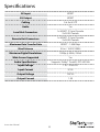
1
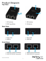
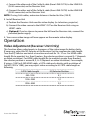
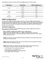
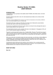
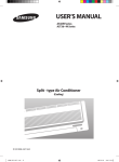
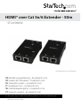
HDMI® over Cat 5e/6 Extender - 50m
ST121SHD50
*actual product may vary from photos
DE: Bedienungsanleitung - de.startech.com
FR: Guide de l'utilisateur - fr.startech.com
ES: Guía del usuario - es.startech.com
IT: Guida per l'uso - it.startech.com
NL: Gebruiksaanwijzing - nl.startech.com
PT: Guia do usuário - pt.startech.com
For the most up-to-date information, please visit: www.startech.com
Manual Revision: 01/31/2014
FCC Compliance Statement
This equipment has been tested and found to comply with the limits for a Class B digital
device, pursuant to part 15 of the FCC Rules. These limits are designed to provide reasonable
protection against harmful interference in a residential installation. This equipment generates,
uses and can radiate radio frequency energy and, if not installed and used in accordance with
the instructions, may cause harmful interference to radio communications. However, there
is no guarantee that interference will not occur in a particular installation. If this equipment
does cause harmful interference to radio or television reception, which can be determined by
turning the equipment off and on, the user is encouraged to try to correct the interference by
one or more of the following measures:
• Reorient or relocate the receiving antenna.
• Increase the separation between the equipment and receiver.
• Connect the equipment into an outlet on a circuit different from that to which the receiver
is connected.
• Consult the dealer or an experienced radio/TV technician for help.
Use of Trademarks, Registered Trademarks, and other Protected Names and Symbols
This manual may make reference to trademarks, registered trademarks, and other
protected names and/or symbols of third-party companies not related in any way to
StarTech.com. Where they occur these references are for illustrative purposes only and do not
represent an endorsement of a product or service by StarTech.com, or an endorsement of the
product(s) to which this manual applies by the third-party company in question. Regardless
of any direct acknowledgement elsewhere in the body of this document, StarTech.com hereby
acknowledges that all trademarks, registered trademarks, service marks, and other protected
names and/or symbols contained in this manual and related documents are the property of
their respective holders.
Instruction Manual
Table of Contents
Product Diagram.....................................................................................1
Top View........................................................................................................................................................ 1
Rear View....................................................................................................................................................... 1
Front View..................................................................................................................................................... 1
Introduction.............................................................................................2
Packaging Contents.................................................................................................................................. 2
System Requirements............................................................................................................................... 2
LED Indicator............................................................................................................................................... 3
Installation...............................................................................................4
Preparing Your Site.................................................................................................................................... 4
Hardware Installation............................................................................................................................... 4
Operation.................................................................................................5
Video Adjustment (Receiver Unit Only)............................................................................................. 5
EDID Configuration................................................................................................................................... 6
Specifications...........................................................................................8
Technical Support...................................................................................9
Warranty Information.............................................................................9
Instruction Manual
i
Product Diagram
Top View
1
1
2
2
1. LED Indicator
1. LED Indicator
2. EDID Copy Button
2. EQ Selector
Rear View
1
2
1
1. Power Jack
1. Power Jack
2. HDMI In
2. HDMI Out
2
Front View
2
1
1. LINK OUT A (RJ-45 Connector)
2
1
1. LINK IN A (RJ-45 Connector)
2. LINK OUT B (RJ-45 Connector)
2. LINK IN B (RJ-45 Connector)
Instruction Manual
1
Introduction
The ST121SHD50 HDMI® over CAT5e/6 Video Extender kit lets you extend HDMI® video
and audio up to 165 feet (50 Meters)(1080i) over 2 CAT5e Ethernet cables, or up to
130 Feet (40 Meters)(1080p) over 2 CAT6 Ethernet cables. For added versatility both
the Transmitter and Receiver can be powered by the same single power source using
Power Over Cable (POC).
With support for resolutions up to 1920x1080 and the accompanying digital audio, this
HDMI® extender is a plug-and-play solution that can easily be installed using new or
existing Ethernet infrastructure wiring.
Backed by a StarTech.com 2-year warranty and free lifetime technical support.
Packaging Contents
• 1x HDMI® over CAT5e/6 UTP Transmitter
• 1x HDMI® over CAT5e/6 UTP Receiver
• 1x Universal Power Adapter (EU, UK, NA)
• 2x Mounting Brackets
• 2x Foot Pad Set
• 1x User Manual
System Requirements
• HDMI® enabled video source device (i.e. computer, Blu-ray Player)
• HDMI® enabled display device (i.e. television, projector)
• Available AC electrical outlet for either the transmitter or receiver
• HDMI® cables for Receiver and Transmitter
Instruction Manual
2
LED Indicator
Status
Transmitter
DVI EDID content configured
*Emit blue with green flashing twice
HDMI EDID content configured
*Emit blue with green flashing three times
HDCP syncing
**Purple
Status
Receiver
Video Linking
***Steady Blue
Video unlinking
Steady Red
*It is suggested replacing cables with better quality ones if the LED emits blue without
video displaying.
**The emitting period of purple LED depends on connected device.
***The LED emits steady blue indicating that the video signal is detected by Receiver.
Instruction Manual
3
Installation
Preparing Your Site
1. Determine where the local video source (i.e. computer, Blu-ray Player) will be
located and set up the device.
2. Determine where the remote display will be located and place/ mount the
display appropriately.
NOTE: This HDMI® extender kit features Power over cable, allowing both the
Transmitter and Receiver to be powered from a single power source that can be
connected at either end of the connection. Please ensure that either the Transmitter
or the Receiver Unit is situated near an available AC electrical outlet. Make sure all
devices are turned off before beginning installation.
Hardware Installation
1. Install Transmitter Unit
a) Position the Transmitter Unit near the video source (i.e. Computer, Blu-ray Player).
b) Connect an HDMI® cable from the video source device (i.e. computer, Blu-ray Player) to the “HDMI® IN” on the Transmitter Unit.
c) (Optional) If you’ve chosen to power the kit from the Transmitter side, connect the provided power supply.
2. Install RJ45 terminated Cat5e/6 Ethernet Cables
a) Connect an RJ45 terminated Cat5e/6 Ethernet cable (not included) to the LINK OUT A (RJ-45 connector) on the Transmitter unit.
b) Connect another RJ45 terminated Cat5e/6 Ethernet cable (not included) to the LINK OUT B (RJ-45 connector) on the Transmitter unit.
NOTE:
If you are using surface cabling, ensure you have enough Category 5e unshielded
twisted pair (UTP) network cabling to connect the Host Unit to the Remote Unit’s
location, and that each end is terminated with a RJ45 connector. The cabling should
not go through any networking equipment (i.e. router, switch).
OR
If you are using premises cabling, ensure that the Category 5 unshielded twisted pair (UTP) network cabling between the Host Unit and theRemote Unit has been properly
terminated in a wall outlet in each location and there is a patch cable long enough
to connect the Remote Unit and the Host Unit to their respective outlets. The cabling
should not go through any networking equipment (i.e. router, switch).
Instruction Manual
4
c) Connect the other end of the Cat5e/6 cable (from LINK OUT A) to the LINK IN A (RJ-45 connector) on the Receiver Unit.
d) Connect the other end of the Cat5e/6 cable (from LINK OUT B) to the LINK IN B (RJ-45 connector) on the Receiver Unit.
NOTE: If using Cat6 cables, extension distance is limited to 40m (130 ft)
3. Install Receiver Unit
a) Position the Receiver Unit near the video display (i.e. television, projector).
b) Connect the video source to the HDMI® OUT on the Receiver Unit using an
HDMI® cable.
c) (Optional) If you’ve chosen to power the kit from the Receiver side, connect the provided power supply.
4. Your source video image will now appear on the remote video display.
Operation
Video Adjustment (Receiver Unit Only)
This function allows adjustments in sharpness of the video image for better clarity.
If necessary, adjust the EQ Selector at the Receiver Unit to compensate cable length.
Turn the EQ Selector one notch at one time and wait for 10~12 sec. For HDMI cable
length (Rx-to-monitor) less than 8 meters, the selector position is around 0~7 (depends
on video resolution). For HDMI cable length (Rx-to-monitor) greater than 8 meters,
the selector position is around 8, 9, A~F (depends on video resolution). For example,
if using a 1.8M (or 3.0M) HDMI cable, a CAT5 cable and a display with resolution of
Full HD (1920 x 1080), you may adjust video according to its CAT5 cable length as
following.
Instruction Manual
CAT5 Cable Length
EQ Selector Position
0M~15M
0,1
15M~25M
1,2
25M~30M
2,3
5
The following is the test result while using different types of CATx cables
Cable Type
CAT6
CAT5
(solid)
CAT5
(stranded)
Resolution
Cable Length (max.)
1080i
50M
1080p
40M
1080i
50M
1080p
20M
1080i
40M
1080p
16M
EDID Configuration
In some cases display problems may occur due to incorrect EDID communication
between the display monitor and the unit or inappropriate EDID data programmed by
display manufactures. This EDID Copy feature allows the system either automatically
provide the necessary EDID to display or manually copy EDID from EDID compliant
displays via push button.
Auto EDID Configuration
The system can automatically read EDID from your display while two RJ-45 ports
(Video & Aux) are in connection.
Manual EDID Configuration (EDID Copy / EDID Ghost)
While using only one CATx cable, it is suggested applying EDID Copy first.
Step 1. Use CATx cable for connection between Tx & Rx on Aux RJ-45 Jack. Apply
power to Receiver Unit.
Step 2. Connect the monitor (EDID compliant) to Video Out on the Receiver Unit
and power on the monitor.
Step 3. Press the button “EDID Copy” on Transmitter Unit and release the button
RIGHT AFTER the LED flashes green.
Step 4. The LED flashes green & red and then it lights blue indicating copy
successfully. Otherwise, if the LED flashes RED, it means that
a. The monitor is not properly connected.
b. The monitor is not powered on.
c. EDID data of the monitor is not applicable.
Try to repeat Step 3 to 4 again.
Instruction Manual
6
EDID Factory Default Setting
To avoid confusion in which EDID information has been copied or for more purposes,
this function enables to reset the state to factory default.
Step 1. Use CATx cable for connection between Tx & Rx on Aux RJ-45 Jack. Apply
power to Receiver Unit.
Step 2. Press the button “EDID Copy” and release the button RIGHT AFTER the LED
flashes red.
Step 3. The LED flashes green & red indicating default setting successfully.
DDC Pass Mode
Press the button for more than 15 sec. and release right after the LED flashes green.
The LED lights blue indicating setting successfully. To exit this mode, follow “EDID
Factory Default Setting” steps.
Instruction Manual
7
Specifications
AV Input
HDMI®
AV Output
HDMI®
Cabling
Cat 5e/6 UTP
Audio
Yes
Local Unit Connectors
1x HDMI® (19 pin) Female
2x RJ-45 Female
Remote Unit Connectors
1x HDMI® (19 pin) Female
2x RJ-45 Female
Maximum Data Transfer Rate
HDMI® - 1.656Gbps
Max Distance
50 m / 165 ft(1080i)
Maximum Digital Resolutions
1080p @ 60Hz, 24-bit
Wide Screen Supported
Yes
Audio Specifications
Supports Dolby® TrueHD, DTS-HD MA
Input Voltage
110 ~ 240V AC
Input Current
0.5 A
Output Voltage
12V DC
Output Current
1.5A
Instruction Manual
8
Technical Support
StarTech.com’s lifetime technical support is an integral part of our commitment to
provide industry-leading solutions. If you ever need help with your product, visit
www.startech.com/support and access our comprehensive selection of online tools,
documentation, and downloads.
For the latest drivers/software, please visit www.startech.com/downloads
Warranty Information
This product is backed by a two year warranty.
In addition, StarTech.com warrants its products against defects in materials
and workmanship for the periods noted, following the initial date of purchase.
During this period, the products may be returned for repair, or replacement with
equivalent products at our discretion. The warranty covers parts and labor costs only.
StarTech.com does not warrant its products from defects or damages arising from
misuse, abuse, alteration, or normal wear and tear.
Limitation of Liability
In no event shall the liability of StarTech.com Ltd. and StarTech.com USA LLP (or their
officers, directors, employees or agents) for any damages (whether direct or indirect,
special, punitive, incidental, consequential, or otherwise), loss of profits, loss of business,
or any pecuniary loss, arising out of or related to the use of the product exceed the
actual price paid for the product. Some states do not allow the exclusion or limitation
of incidental or consequential damages. If such laws apply, the limitations or exclusions
contained in this statement may not apply to you.
Instruction Manual
9
Hard-to-find made easy. At StarTech.com, that isn’t a slogan. It’s a promise.
StarTech.com is your one-stop source for every connectivity part you need. From
the latest technology to legacy products — and all the parts that bridge the old and
new — we can help you find the parts that connect your solutions.
We make it easy to locate the parts, and we quickly deliver them wherever they need
to go. Just talk to one of our tech advisors or visit our website. You’ll be connected to
the products you need in no time.
Visit www.startech.com for complete information on all StarTech.com products and
to access exclusive resources and time-saving tools.
StarTech.com is an ISO 9001 Registered manufacturer of connectivity and technology
parts. StarTech.com was founded in 1985 and has operations in the United States,
Canada, the United Kingdom and Taiwan servicing a worldwide market.