1
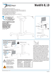
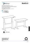
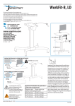
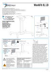
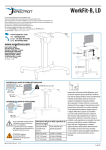
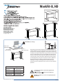
WorkFit-B, HD
www.ergotron.com
User's Guide - English
Guía del usuario - Español
Manuel de l’utilisateur - Français
Gebruikersgids - Nederlands
Benutzerhandbuch - Deutsch
Guida per l’utente - Italiano
Användarhandbok - svenska
ユーザーガイド : 日本語
用户指南 : 汉语
22.5-88 lbs (10.2-40 kg)*
0.80”-1.75”*
(20-44 mm)
41"-72" *
(1041-1829 mm)
23.5”-30.5”*
(597-775 mm)
Important! You will need to adjust this product after installation is
complete. Make sure all your equipment is properly installed on the
product before attempting adjustments. This product should move
smoothly and easily through the full range of motion and stay where
you set it. If movements are too easy or difficult or if product does
not stay in desired positions, follow the adjustment instructions to
create smooth and easy movements. Depending on your product
and the adjustment, it may take many turns to notice a difference.
Any time equipment is added or removed from this product,
resulting in a change in the weight of the mounted load, you
should repeat these adjustment steps to ensure safe and optimum
operation.
Wood Worksurface Weight Estimator
Worksurface
Thickness
Estimated Weight
per square foot
0.80” (20 mm)
2.9 lbs (1.32 kg)
1.25” (32 mm)
4.5 lbs (2.04 kg)
1.75” (44 mm)
6.3 lbs (2.86 kg)
*Total weight of worksurface and mounted equipment must
be < 88 lbs (40 kg).
Worksurface must meet ALL dimensional and weight range
specification requirements.
WARNING! The addition of accessories can negatively impact the
tip performance.
888-24-227-G-00 rev. B • 07/13
1 of 18
Hazard Symbols Review
Symbol
These symbols alert users of a safety condition that
demands attention. All users should be able to
recognize and understand the significance of the following Safety Hazards if encountered on the product
or within the documentation. Children who are not
able to recognize and respond appropriately to Safety
Alerts should not use this product without adult
supervision!
Signal Word
Level of Hazard
NOTE
A NOTE indicates important information that helps you
make better use of this product.
CAUTION
A CAUTION indicates either potential damage to
hardware or loss of data and tells you how to avoid the
problem.
WARNING
A WARNING indicates either potential for property damage, personal injury, or death.
ELECTRICAL
An Electrical indicates an impending electrical hazard
which, if not avoided, may result in personal injury, fire
and/or death.
Safety
WARNING
IMPACT HAZARD
Moving Parts Can Crush And Cut
Minimize Lift Strength BEFORE:
- Removing Mounted Equipment
and
Insert 4 Stop Screws BEFORE:
- Shipping or Storing (i.e. when Desk is not upright).
To Minimize Lift Strength
Refer to installation manual for instructions on
how to minimize lift strength.
To Insert 4 Stop Screws
Refer to installation manual for instructions on
installing stop screws.
Failure to heed this warning may result in
serious personal injury or property damage!
For More information and instructions visit www.ergotron.com
or contact Ergotron Customer Care at 1-800-888-8458.
826-901-00
Refer to Appendix A at the end of this manual
Refer to Appendix B at the end of this manual
888-24-227-G-00 rev. B • 07/13
2 of 18
Safety
WARNING! Stop screws are pre-installed in this product to secure it in the compressed position
during shipping and installation. DO NOT REMOVE THESE SCREWS UNTIL INSTRUCTED TO DO SO
IN THESE INSTRUCTIONS. Make sure these screws are in place before starting installation. Failure
to follow these instructions may cause lift engine to expand rapidly and may result in equipment
damage and or personal injury. If any of the 4 stop screws are not installed in these locations,
contact customer care before continuing with installation.
DO NOT REMOVE SCREWS!
IMPORTANT!
Save these stop screws and instructions. Install stop screws
when shipping or storing this product. Failure to follow
these instructions may cause lift engine to expand rapidly
and may result in equipment damage and or personal
injury.
3
4
DO NOT REMOVE SCREWS!
1
2
888-24-227-G-00 rev. B • 07/13
3 of 18
Safety
Important! You will need to adjust this product after installation is complete. Make sure all your equipment is properly
installed on the product before attempting adjustments. This product should move smoothly and easily through
the full range of motion and stay where you set it. If movements are too easy or difficult or if product does not stay
in desired positions, follow the adjustment instructions to create smooth and easy movements. Depending on your
product and the adjustment, it may take many turns to notice a difference. Any time equipment is added or removed
from this product, resulting in a change in the weight of the mounted load, you should repeat these adjustment steps
to ensure safe and optimum operation.
WARNING
Keep Brake Cables Away from
Sync Rod and Crossbars
During Installation!
WARNING! TIPPING HAZARD!
When mounting accessories to the
WorkFit-D, they must stay within the foot
print. Do not mount accessories past the
front and rear worksurface! Failure to follow this warning may result in equipment
damage and or personal injury.
Failure to keep the brake cables away from
sync rod and crossbars may restrict lift
motion and may cause equipment damage
or personal injury! Refer to instruction
manual for more information.
888-24-227-G-00 rev. B • 07/13
4 of 18
Components
A
B
1x
C
1x
1x
1
2x
16x
2
M5 x 6mm
17x
#12-14 x 5/8”
3x
3x
3
M2.9 x 8mm
2x
4.25” (108 mm)
3.75” (95 mm)
3.25” (83 mm)
1x
2.75” (70 mm)
2.25” (57 mm)
1.75” (44 mm)
1.25” (32 mm)
0.75” (19 mm)
ST3.9 x 16mm
4.25” (108 mm)
WORKSURFACE TEMPLATE FOR WORKFIT-B, HD
Lay this template on the bottom of your worksurface
See table for value of X based on the depth of
to drill the holes to attach the WorkFit-D, Base.
your worksurface.
3.75” (95 mm)
3.25” (83 mm)
Align REAR Edge of Worksurface X distance
2.75” (70 mm)
X from the back of the Base Brackets.
0.25” (6 mm)
2.126
4x
2.25” (57 mm)
1.75” (44 mm)
1.25” (32 mm)
0.75” (19 mm)
0.25” (6 mm)
Back of Base Bracket
1x
2.5 mm
2.126
35.197
12.992
Depth of
Worksurface
23.50 - 24.25”----0.25”
24.25 - 25.00”----0.75”
25.00 - 25.75”----1.25”
25.75 - 26.50”----1.75”
26.50 - 27.25”----2.25”
27.25 - 28.00”----2.75”
28.00 - 28.75”----3.25”
28.75 - 29.50”----3.75”
29.50 - 30.25”----4.25”
X
4
5.118
Use Drill Bit #21,
Ø 0.19” (4.8 mm)
to drill these 8 holes
0.375” (9.5 mm) deep.
Brake Release
Depth of
Worksurface
597 - 616 mm ---6 mm
616 - 635 mm ---19 mm
635 - 654 mm ---32 mm
654 - 673 mm ---44 mm
673 - 692 mm ---57 mm
692 - 711 mm ---70 mm
711 - 730 mm ---83 mm
730 - 749 mm ---95 mm
749 - 768 mm ---108 mm
X
Center Point of Base Brackets
Use Drill Bit #46,
Ø 0.081” (2mm)
to drill these 3 holes
0.24” (6 mm) deep.
Use Drill Bit #21,
Ø 0.19” (4.8 mm)
to drill these 9 holes
0.375” (9.5 mm) deep.
TIPPING HAZARD!
Center Worksurface from Side-to-Side Across Base Brackets.
Failure to follow these instructions may make this product unstable
and may result in equipment damage and/or personal injury.
3.900
DIMENSIONS ARE IN INCHES
823-558-00 rev.A 05/13
Tools Needed
1/4”
14mm
#21, Ø 0.19” (4.8mm)
#46, Ø 0.081” (2mm)
888-24-227-G-00 rev. B • 07/13
5 of 18
Set-up Steps
1
Place the worksurface on a clean floor with the top side facing down.
Center Template
Side-to-Side on
worksurface.
,
Bit #46
(2mem)
UseØDrill
s
0.081”thes
3 hole
) deep.
to drill
0.24” (6 mm
,
Bit #21mm
)
Use Drill
” (4.8e 9 holes
Ø 0.19thes
) deep.
to drill
3/8” (9.5 mm
,
Bit #21mm
)
Use Drill
” (4.8these 8 holes p.
Ø 0.19drill
) dee
to
3/8” (9.5 mm
Brake Rele
kets
of Base Brac
e
Bracket ts.
!
unstabl
Basepro
duc al
HAZARD Across
injury.
e this
TIPPINGSide-to-Side
makand
/or person
e from ructions may
ent damage
Worksuwrfac
theseininst
Centerto
follo resu
lt equipm
Failureand
may
t
Center Poin
ase
Align REAR Edge of Worksurface X distance from the back of the Base Brackets.
See table for value of X based on the depth of your worksurface.
,
l Bit #46
(2mem)
UseØDril
s
0.081”thes
3 hole
) deep.
to drill
0.24” (6 mm
,
l Bit #21mm
)
Use Dril
” (4.8e 9 holes
Ø 0.19thes
) deep.
to drill
3/8” (9.5 mm
,
l Bit #21mm
)
Use Dril
” (4.8these 8 holes p.
Ø 0.19drill
) dee
to
3/8” (9.5 mm
Brackets
t of Base
ckets.
le
Center Poin
!
unstabry.
Base Bra
ductal
HAZARD Across
inju
e this pro
TIPPINGSide-to-Side
may makand/or person
rfacesefrom
ructions
ent damage
Worksu
the ininst
Centerto
followresu
lt equipm
Failureand
may
ase
Brake Rele
Depth of
Your Worksurface
Depth of
Worksurface
23.50 - 24.25”----0.25”
24.25 - 25.00”----0.75”
25.00 - 25.75”----1.25”
25.75 - 26.50”----1.75”
26.50 - 27.25”----2.25”
27.25 - 28.00”----2.75”
28.00 - 28.75”----3.25”
28.75 - 29.50”----3.75”
29.50 - 30.25”----4.25”
X
4.25” (108 mm)
3.75” (95 mm)
3.25” (83 mm)
2.75” (70 mm)
2.25” (57 mm)
1.75” (44 mm)
1.25” (32 mm)
0.75” (19 mm)
Align REAR Edge of Worksurface X distance
X from the back of the Base Brackets.
See table for value of X based on the depth of
your worksurface.
0.25” (6 mm)
2.126
Back of Base Bracket
2.126
Depth of
Worksurface
597 - 616 mm ---6 mm
616 - 635 mm ---19 mm
635 - 654 mm ---32 mm
654 - 673 mm ---44 mm
673 - 692 mm ---57 mm
692 - 711 mm ---70 mm
711 - 730 mm ---83 mm
730 - 749 mm ---95 mm
749 - 768 mm ---108 mm
X
Tape Template in place.
,
l Bit #46
(2mem)
UseØDril
s
0.081”thes
3 hole
) deep.
to drill
0.24” (6 mm
,
l Bit #21mm
)
Use Dril
” (4.8e 9 holes
Ø 0.19thes
) deep.
to drill
3/8” (9.5 mm
,
l Bit #21mm
)
Use Dril
” (4.8these 8 holes p.
Ø 0.19drill
) dee
to
3/8” (9.5 mm
Brackets
t of Base
le
Bracket ts.
Center Poin
!
unstabry.
Basepro
duc al
HAZARD Across
inju
e this
TIPPINGSide-to-Side
makand
/or person
e from ructions may
ent damage
Worksuwrfac
theseininst
Centerto
follo resu
lt equipm
Failureand
may
ase
Brake Rele
888-24-227-G-00 rev. B • 07/13
6 of 18
Set-up Steps
Using the specified drill bit, drill the 17 holes for base.
#21, Ø 0.19” (4.8mm)
Drill holes 0.375" (9.5 mm) deep.
TIP: To ensure proper depth, place a
piece of tape on the drill bit 0.375” (9.5
mm) from the tip.
,
ll Bit #46
(2mm) holes
UseØDri
0.081”
ll these 3 ) deep.
to dri
0.24” (6 mm
#21, )
ll Bit(4.8
mm
Use Dri
Ø 0.1ll9”the
se 9 hol) es
deep.
to dri3/8
” (9.5 mm
#21, )
ll Bit(4.8
mm 8 holes
Use Dri
se ) deep.
Ø 0.19”
to drill”the
3/8 (9.5 mm
Brackets
nt of Base
ts. ble
Bracke
Center Poi
!
unstaury.
Basepro
ossthi
duct
ZARDide
s
G HAe-t
o-S yAcr
rsonal inj
TIPPIN
make
m Sidctio
and/or pe
ns ma
ace fro
instru
rksurfthe
nt damage
se
Wo
ter
Cen to follow ult in equipme
Failureand
may res
ease
Brake Rel
0.375"
(9.5 mm)
Using the specified drill bit, drill the 3 holes for cable clips.
#46, Ø 0.081” (2mm)
Drill holes 0.24" (6 mm) deep.
TIP: To ensure proper depth, place a piece of tape on the drill bit
0.24" (6 mm) from the tip.
,
ll Bit #46
(2mm) holes
UseØDri
0.081”
ll these 3 ) deep.
to dri
0.24” (6 mm
#21, )
ll Bit(4.8
mm
Use Dri
Ø 0.1ll9”the
se 9 hol) es
deep.
to dri3/8
” (9.5 mm
#21, )
ll Bit(4.8
mm 8 holes
Use Dri
se ) deep.
Ø 0.19”
to drill”the
3/8 (9.5 mm
Brackets
nt of Base
ts. ble
Bracke
Center Poi
!
unstaury.
Basepro
ossthi
duct
ZARDide
s
G HAe-t
o-S yAcr
rsonal inj
TIPPIN
make
m Sidctio
and/or pe
ns ma
urfacesefro
instru
nt damage
Works
the
low
eq
Center
in uipme
to fol
Failureand
may result
ease
Brake Rel
0.24"
(6 mm)
Remove Template.
TE FOR
TEMPLA
URFACE
S
WORKS
IN INCHE
DIMENSIONS
E
IT-D, BAS
WORKF
ONLY
ARE
888-24-227-G-00 rev. B • 07/13
7 of 18
Front Edge of Worksurface
Set-up Steps
2
Place the worksurface on a clean floor with
the top side facing down.
Carefully position the leg with the hand
brake on the right end of the worksurface.
Place the other leg on the left end.
Rear Edge of Worksurface
NOTE: The brake cable is attached to both legs. Take care when removing the legs from the packaging to avoid damaging or pulling the
brake cable from the legs.
3
Set the right leg (with hand brake) upright on the
worksurface.
Partially insert 3 of the provided #12-14 wood
screws at the rear of the leg, 3 near the middle of
the leg and 2 at the front of the leg.
Front =2 screws
Middle = 3 screws
8x
#12-14 x 5/8”
NOTE: Do not fully
insert the screws
into the worksurface
at this time. Leave
approximately 1/8”
space.
4
Attach one end of the sync rod to the
right leg as illustrated. Make sure the
brake cables don’t loop around the sync
rod. See Warning, right.
Rear = 3 screws
WARNING
Keep Brake Cables Away from
Sync Rod and Crossbars
During Installation!
Failure to keep the brake cables away from
sync rod and crossbars may restrict lift
motion and may cause equipment damage
or personal injury! Refer to instruction
manual for more information.
888-24-227-G-00 rev. B • 07/13
8 of 18
WARNING
Set-up Steps
Keep Brake Cables Away from
Sync Rod and Crossbars
During Installation!
Failure to keep the brake cables away from
sync rod and crossbars may restrict lift
motion and may cause equipment damage
or personal injury! Refer to instruction
manual for more information.
5
Set the left leg (without
hand brake) upright on the
worksurface.
Attach the left end of the
sync rod to the left leg.
Make sure the brake cables
don’t loop around the sync
rod. See Warning, right.
6
Partially insert 9 of the provided #12-14 wood screws
in the left leg and worksurface.
Front =2 screws
Middle = 3 screws
NOTE: Do not
fully insert
the screws
into the worksurface at this
time. Leave
approximately 1/8” space.
9x
#12-14 x 5/8”
Rear = 3 screws
7
Use a Phillips screwdriver to insert the provided M5x6
mm screws into the two crossbars connecting the left
and right legs. Make sure the brake cables don’t
loop around the crossbars.
16x
M5 x 6mm
Tighten the screws slightly one at a time
and repeat to ensure that the tension
on every screw is equal.
NOTE: Do not overtighten screws.
overtightening screws may result in stripping
the holes and may cause the installation to be
unsafe.
8
Use a Phillips screwdriver to tighten
down the screws attaching the legs to
the worksurface.
NOTE: Do not overtighten screws. overtightening
screws may result in stripping the holes and may
cause the installation to be unsafe.
888-24-227-G-00 rev. B • 07/13
9 of 18
Set-up Steps
9
If your brake release handle is not aligned with the front edge of your worksurface and you
would like it to be, follow these instructions to relocate the brake release handle.
a
b
c
Relocate brake release handle along front edge of worksurface and next to the inside of
the leg only. DO NOT attach brake release handle in front of or to the outside of the leg.
Make sure cable has enough slack to allow worksurface to fully extend up and down.
#46, Ø 0.081” (2mm)
d
4x
ST3.9 x 16mm
888-24-227-G-00 rev. B • 07/13
10 of 18
Set-up Steps
10
11
Capture the brake cable in the cable clip as
illustrated, then use a Phillips screwdriver
to attach the cable clips to bottom of work
surface with the provided M2.9 x 8 mm screws.
3x
Using the 2 provided cable ties, attach brake cable
to the legs leaving as much slack in cable as possible
between the cable tie and the leg to allow desk top to
raise up unrestricted.
3x
M2.9 x 8mm
2x
NOTE: Leave as much
slack in cable as possible
between the cable tie and
the leg to allow desk top
to raise up unrestricted.
Failure to follow this
may result in equipment
damage.
888-24-227-G-00 rev. B • 07/13
11 of 18
Set-up Steps
12
Set the desk upright onto its legs.
CAUTION!
LIFT HAZARD!
Two persons are required for
this step. Failure to follow
this warning may result in
equipment damage and or
personal injury.
13
Adjust the riser on each leg and check with a level to
make sure the work surface is even.
Spin Left to Raise.
Spin Right to Lower.
888-24-227-G-00 rev. B • 07/13
12 of 18
Set-up Steps
14
Remove the 4 brake stop screws before installing equipment.
Remove the 2 stop screws from the legs then the 2 stop screws from
the brake to allow the worksurface to raise and lower.
1
IMPORTANT!
Save these stop screws and instructions. Install stop
screws when shipping or storing this product. Failure
to follow these instructions may cause lift engine to
expand rapidly and may result in equipment damage
and or personal injury.
2
2.5 mm
After you remove the 4 brake stop
screws, release the hand brake
(on the right leg) and move the
worksurface up to highest level.
888-24-227-G-00 rev. B • 07/13
13 of 18
Set-up Steps
15
Install all equipment.
CAUTION! Make sure you leave 20” (508mm)
of slack in all equipment cables to allow the
worksurface to raise up it’s full 20” (508mm).
Failure to allow enough slack in equipment
cables may cause cables to get pulled,
equipment to fall off desk and may result in
product damage and or personal injury.
16 Adjustment Step
Important! You will need to adjust this product after installation is complete. Make sure all your equipment is properly
installed on the product before attempting adjustments. This product should move smoothly and easily through
the full range of motion and stay where you set it. If movements are too easy or difficult or if product does not stay
in desired positions, follow the adjustment instructions to create smooth and easy movements. Depending on your
product and the adjustment, it may take many turns to notice a difference. Any time equipment is added or removed
from this product, resulting in a change in the weight of the mounted load, you should repeat these adjustment steps
to ensure safe and optimum operation.
WARNING
IMPACT HAZARD
Moving Parts Can Crush And Cut
Minimize Lift Strength BEFORE:
- Removing Mounted Equipment
and
Insert 4 Stop Screws BEFORE:
- Shipping or Storing (i.e. when Desk is not upright).
To Minimize Lift Strength
Refer to installation manual for instructions on
how to minimize lift strength.
To Insert 4 Stop Screws
Refer to installation manual for instructions on
installing stop screws.
Failure to heed this warning may result in
serious personal injury or property damage!
For More information and instructions visit www.ergotron.com
or contact Ergotron Customer Care at 1-800-888-8458.
826-901-00
888-24-227-G-00 rev. B • 07/13
14 of 18
17 Adjustment Step
Release the hand brake (on the right leg) and move
the worksurface up to highest level.
Push in the cover located behind each leg to access
the adjustment point.
NOTE: The covers on the legs will not open
unless the worksurface has been lifted to it’s full
height. The worksurface will not lower unless
the covers have been completely closed.
Maintain equal amount of tension on both legs by
alternating the adjustment from one leg to the other
using a 14mm socket drill.
14mm
Increase Lift Strength
If the mounted weight is too heavy or this
product does not stay up when raised, then you'll
need to increase Lift Strength:
Decrease Lift Strength
If the mounted weight is too light or this product
does not stay down when lowered, then you'll
need to decrease Lift Strength:
Make sure
covers are fully
closed before
lowering the
worksurface.
=
WARNING! DO NOT tip desk over to adjust. Only perform adjustment while desk is upright.
Failure to follow these instructions may cause the lift engine to expand rapidly and may result in
equipment damage and or personal injury.
888-24-227-G-00 rev. B • 07/13
15 of 18
APPENDIX A - Minimize Lift Tension
WARNING. Before removing mounted equipment (monitor, arm, stand CPU, etc.), from desk, or
to prepare for shipping or storing the desk it is extremely important to minimize the lift tension.
Failure to install these instructions may cause lift engine to expand rapidly and may result in
equipment damage and or personal injury.
1. Release the hand brake (on the right leg) and move the worksurface up to
highest level.
2. Push in the cover located behind each leg to access the adjustment point.
NOTE: The covers on the legs will not open unless
the worksurface has been lifted to it’s full height. The
worksurface will not lower unless the covers have been
completely closed.
3. To minimize tension, turn adjustment bolts left using a 14mm
socket drill. Maintain equal tension on both legs by alternating
adjustment from one leg to the other. Keep adjusting until the
wrench stops turning.
4. Once at minimum tension it is ok to remove mounted equipment.
14mm
Turn adjustment
bolts left to
minimize tension.
Make sure
covers are fully
closed before
lowering the
worksurface.
=
WARNING! DO NOT tip desk over to adjust. Only perform adjustment while desk is
upright. Failure to follow these instructions may cause the lift engine to expand rapidly
and may result in equipment damage and or personal injury.
888-24-227-G-00 rev. B • 07/13
16 of 18
APPENDIX B - Inserting Stop Screws
WARNING. Before shipping or storing the desk, or in cases where the desk is placed on it’s back
or side*, it is extremely important that the 4 stop screws be re-inserted. Failure to follow these
instructions may cause lift engine to expand rapidly and may result in equipment damage and
or personal injury.
1. Follow instructions in Appendix A to minimize lift tension.
2. Push the desk down to its lowest position.
3. Insert 2 stop screws at the bottom of each leg.
4. Insert the other 2 stop screws on each side of the hand brake located on the right
side of the worksurface.
5. Once the 4 stop screws have been
installed the desk can be shipped
or stored.
1
* Placing the desk on its back or side is not
recommended.
2
2.5 mm
888-24-227-G-00 rev. B • 07/13
17 of 18
Set Your Workstation to Work For YOU!
Configure su estación de trabajo para que trabaje para USTED.
Ajustez votre station de travail en fonction de VOS besoins !
Richten Sie Ihren Arbeitsplatz so ein, dass er für SIE arbeitet!
Stel uw werkstation zo in dat het voor U werkt!
Approntare la stazione di lavoro nella posizione ergonomica ottimale.
一人ひとりにピッタリのワークステーション!
按照您自身的需要设置工作站!
Learn more about ergonomic computer use at:
Más información sobre el uso ergonómico de ordenadores:
Apprenez-en plus sur l’utilisation ergonomique d’un ordinateur sur :
Weitere Informationen zur ergonomischen Computernutzung finden Sie unter:
Leer meer over ergonomisch computergebruik op:
Per ulteriori informazioni sull’uso ergonomico del computer:
人間工学的なコンピュータの使用法については次のサイトを参照してください
想进一步了解以符合人体工程学的方式使用计算机的知识,请访问:
www.computingcomfort.org
Height Position top of screen slightly below eye level.
Position keyboard at about elbow height with wrists flat.
Distance Position screen an arm's length from face—at least 20” (508mm).
Position keyboard close enough to create a 90˚ angle in elbow.
Angle Tilt screen to eliminate glare.
Tilt the keyboard back 10° so that your wrists remain flat.
To Reduce Fatigue
Breathe - Breathe deeply through your nose.
Blink - Blink often to avoid dry eyes.
Break • 2 to 3 minutes every 20 minutes
• 15 to 20 minutes every 2 hours.
Altura Coloque el borde superior de la pantalla ligeramente por debajo de la altura de sus ojos.
Coloque el teclado aproximadamente a la altura de los codos con las muñecas planas.
Distancia Coloque la pantalla a una distancia de un brazo desde la cara, esto es, unos 50 cm (20 pulgadas).
Coloque el teclado lo suficientemente cerca para que el codo forme un ángulo de 90º.
Ángulo Incline la pantalla para eliminar los reflejos.
Incline el teclado 10º hacia atrás para que las muñecas sigan en posición plana.
Para reducir la fatiga
Respirar - Respire hondo por la nariz.
Parpadear - Parpadee a menudo para que no se sequen
los ojos.
Descansar • 2 o 3 minutos cada 20 minutos
• 15 o 20 minutos cada 2 horas.
Hauteur Positionnez l’écran du haut légèrement en dessous du niveau du regard.
Positionnez le clavier à peu près à la même hauteur que vos coudes, pour que vos poignets soient à plat.
Distance Positionnez l’écran à un bras de distance de votre visage, à au moins 508 mm (20 pouces).
Positionnez le clavier assez près pour que vos coudes forment un angle de 90°.
Angle Inclinez l’écran pour ne pas être ébloui.
Inclinez le clavier vers l’arrière de 10° pour que vos poignets soient à plat.
Pour réduire la fatigue
Respirez - Respirez profondément par votre nez.
Clignez des yeux - Clignez souvent des yeux pour ne pas
avoir les yeux secs.
Faites des pauses • 2 à 3 minutes toutes les 20 minutes
• 15 à 20 minutes toutes les 2 heures.
Höhe Positionieren Sie die obere Kante des Bildschirms knapp unter Augenhöhe.
Positionieren Sie die Tastatur bei flach aufgelegten Handgelenken auf Ellenbogenhöhe.
Abstand Positionieren Sie den Bildschirm mindestens eine Armlänge (50 cm) von Ihrem Gesicht entfernt.
Positionieren Sie die Tastatur nahe genug, um einen Ellenbogenwinkel von 90 ˚ zu ermöglichen.
Winkel Neigen Sie den Bildschirm so, dass ein Spiegeleffekt vermieden wird.
Neigen Sei die Tastatur um 10 ° nach hinten, sodass Ihre Handgelenke flach aufliegen.
Vermeiden von Ermüdungserscheinungen
Atmen - Atmen Sie tief durch die Nase ein und aus.
Blinzeln - Blinzeln Sie so oft wie möglich, um trockene
Augen zu vermeiden.
Pausen • Machen Sie alle 20 Minuten eine Pause von
2-3 Minuten
• Machen Sie alle 2 Stunden eine Pause von 15-20 Minuten.
Hoogte Zet de bovenkant van het scherm iets boven ooghoogte.
Plaats het toetsenbord op ongeveer ellebooghoogte met de polsen plat.
Afstand Plaats het scherm op een armlengte van uw gezicht — op ten minste 508 mm (20 in).
Zet uw toetsenbord zo dichtbij dat u een hoek van 90° in de ellebogen hebt.
Hoek Kantel het scherm om weerspiegeling te elimineren.
Kantel het toetsenbord 10° naar achteren, zodat uw polsen plat blijven liggen.
Om vermoeidheid te verminderen
Ademen - Adem diep door uw neus in en uit.
Knipperen - Knipper regelmatig om droge ogen te vermijden.
Pauzes nemen • 2 tot 3 minuten elke 20 minuten
• 15 tot 20 minuten elke 2 uur.
Altezza Posizionare la parte superiore dello schermo leggermente sotto il livello degli occhi.
Posizionare la tastiera circa all’altezza dei gomiti, in modo che i polsi siano piatti.
Distanza Posizionare lo schermo a un braccio di distanza dal viso, almeno a 20" (508 mm) di distanza.
Posizionare la tastiera affinché sia abbastanza vicina da costringere i gomiti a un angolo di 90˚.
Angolazione Inclinare lo schermo in modo da eliminare i riflessi.
Inclinare la tastiera indietro di 10° in modo che i polsi rimangano piatti.
Per ridurre l’affaticamento
Respirazione - Respirare profondamente dal naso.
Battito delle palpebre - Battere spesso le palpebre per
evitare che gli occhi si asciughino.
Pause • Fare una pausa di 2 - 3 minuti ogni 20 minuti
• Fare una pausa di 15 - 20 minuti ogni 2 ore.
高さ スクリーンの上端が目よりわずかに下に来るようにします。
キーボードが、手首を水平に伸ばした状態でひじとほぼ同じ高さに来るようにします。
距離 スクリーンを顔から腕の長さ分(少なくとも508mm)離します。
ひじが直角になる位置にキーボードを置きます。
角度 反射光をなくすようにスクリーンの角度を調整します。
キーボードを後方に 10° 傾けて、手首が水平になるようにします。
疲れを軽減する方法
呼吸 - 鼻から深く呼吸します。
まばたき - 目の乾燥を防ぐために頻繁にまばたきしてく
ださい。
休憩 • 20分ごとに2~3分
• 2時間ごとに15~20分
高度 屏幕顶端的位置要稍低于视线高度。
将键盘放置在大约肘部的高度并且手腕要能放平。
距离 将屏幕摆放在距离面部一臂长的位置——至少 508mm (20”)。
键盘的位置要够近,以使肘部形成直角。
角度 倾斜屏幕以消除眩光。
将键盘向后倾斜 10 度,使手腕能保持放平。
为了减轻疲劳
呼吸 - 通过鼻子深呼吸。
眨眼 - 经常眨眼可避免眼睛干涩。
休息 • 每隔 20 分钟休息 2 至 3 分钟
• 每隔 2 小时休息 15 至 20 分钟.
888-24-227-G-00 rev. B • 07/13
18 of 18