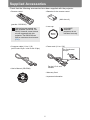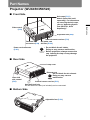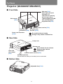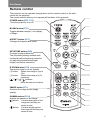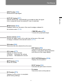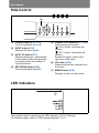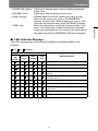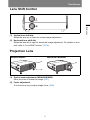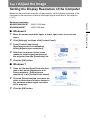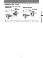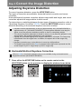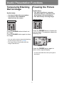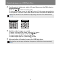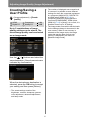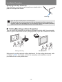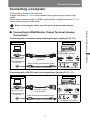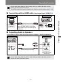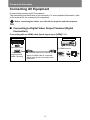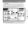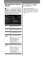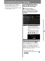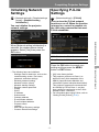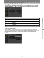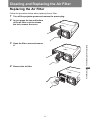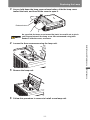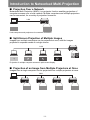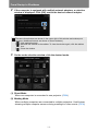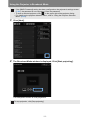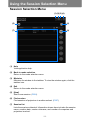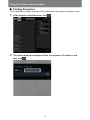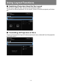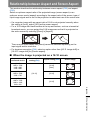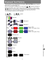
1
Table of Contents
MULTIMEDIA PROJECTOR
Safety Instructions
Before Use
Projecting an Image
Operation
User’s Manual
Useful Functions Available
During a Presentation
Setting Functions from
Menus
Installation and Maintenance
Installation
Connecting to a Network
Maintenance
Networked Multi-Projection
Networked Multi-Projection
Overview
Appendix
Other Information
Operation in Each Mode
Functions in All Modes
Index
ENG
How to Use This Manual
Thank you for purchasing a Canon projector.
The WUX450/WX520/WUX400ST/WX450ST Multimedia Projector (hereinafter
referred to as “the projector”) is a high-performance projector that is capable
of projecting a high-resolution computer screen and high-quality digital
image on a large screen.
This Manual
This manual combines the user’s manual for WUX450/WX520/WUX400ST/
WX450ST Multimedia Projectors. The “Operation” section (P49) describes how to
use the projector. The “Installation and Maintenance” section (P123) describes
initial setup and regular maintenance. For instructions on software for projection by
multiple projectors linked in a local network, refer to the “Networked Multi-Projection
(NMPJ)” section (P205). Read this manual thoroughly to make the most of your
projector. Installation of the projector should be performed by a qualified technician,
if possible. Contact the Canon Customer Support Center for further information.
Unless otherwise noted, figures in this manual show the WUX450/WX520.
Symbols of Button Operations
The projector can be operated using the buttons on the remote control or on the
side of the projector. The remote control allows you to operate all functions of the
projector.
In this document, the button’s operations are shown as below.
Operation of buttons
on side of projector
Selecting Screen Aspect
Select the correct aspect ratio for the screen which is used.
Remote control button
operation
1
Press the MENU button to display the menu window.
Remote control
2
Projector
Press the [ ] / [ ] buttons to select the [Install settings] tab.
Remote control
Projector
Indicate the buttons to be pressed
Symbols Used in This Manual
Meanings of the symbols used in this manual are as follows.
A precaution about operation or restriction is given here.
Indicates supplemental information to note in use.
2
How to Use This Manual
Copyright Notice
Please note that enlarging or reducing the size of an image for commercial
purposes or public presentation may infringe on the legally protected copyright
or the copyright holder of the original material.
About Trademarks
• Ethernet is a registered trademark of Xerox Corporation.
• Microsoft, Windows, Windows XP, Windows Vista, Windows 7, Windows 8
and Aero are registered trademarks or trademarks of Microsoft Corporation
in the United States and / or other countries.
• Mac, Mac OS and Macintosh are trademarks of Apple Inc., registered in the
United States and / or other countries.
• HDMI, the HDMI logo and High-Definition Multimedia Interface are
trademarks or registered trademarks of HDMI Licensing, LLC.
• PJLink is a registered trademark, or an application has been submitted for
trademark, in Japan, the United States and / or other countries or regions.
• AMX is a trademark of AMX Corporation.
• Crestron®, Crestron RoomView®, and Crestron Connected™ are registered
trademarks of Crestron Electronics, Inc.
3
Projector Highlights
Minimal Space Needed for Installation
Compact body (337 x 134 x 370 mm / 13.3 x 5.3 x 14.6 in (W x H x D) (WUX450/
WX520) or 337 x 134 x 415 mm / 13.3 x 5.3 x 16.3 in (W x H x D) (WUX400ST/
WX450ST)) can be installed with minimal space requirements. (P298)
High-Resolution LCOS Projection
Projection at 1920x1200 (WUXGA) for the WUX450/WUX400ST or 1440x900
(WXGA+) for the WX520/WX450ST, thanks to high-resolution reflective liquid
crystal (LCOS) panels.
Split-Screen Display
Side-by-side projection of two input images from devices connected to the
projector. (P81)
Manual Lens Shift, Zoom, and Focus
Manually adjust image position (P58, P134) and focus (P59) as needed.
Zoom Adjustment to Match Screen Size
The size of the projected image can be adjusted using optical zoom (P57) on the
WUX450/WX520 and electronic zoom (P149) on the WUX400ST/WX450ST.
Close-Range Projection on Large Screens
(WUX400ST/WX450ST)
Close-range projection on wide screens is supported, such as projection on
100-inch screens from about 1.2 meters.
USB File Viewer
Project JPEG images stored on a USB flash. (P79)
Edge Blending
Blend the overlapping edges of images from multiple projectors to make the overall
image more seamless. (P159)
Displaying Test Pattern
Project a range of test patterns, with no image input needed. (P158)
Networked Multi-Projection (NMPJ)
Project images from multiple computers via a network connection. (P205)
4
Quick Reference Guide
This Quick Reference Guide will help you find functions that make full use of the
projector and are useful for producing an attractive presentation, etc.
Changing the Remote Control
Channel (P114)
Connecting the Projector
Connecting to the Computer (P137 - P139)
Connecting to AV Equipment (P140 - P142)
Resetting Projector Setting
Projecting an Image
Canceling the Password (P117)
Starting Projection (P52)
Initializing the Network Setting (P175)
Selecting an Input Signal (P53 - P54)
Restoring Default Menu Settings (P121)
Projecting Images from Two Sources at
Once (P81)
Miscellaneous Functions
Using Auto Power-Off (P110)
Adjusting the Image
Turning on the Projector by Connecting
the Power Cord (P111)
Adjusting the Image Size and Focus
(P57 - P59)
Adjusting Keystone Distortion (P68)
Disabling the Beep During Operation
(P111)
Adjusting Aspect Ratio (P60 - P67)
Disabling Buttons (P112)
Eliminating Flickers from Computer
Screen and Adjusting Positional Shift
(P89, P90)
Hiding Guide Messages (P154)
Setting a Password (P116)
Reducing the Lamp Brightness (P107)
Displaying Test Pattern (P158)
Adjusting Colors and Image Quality
Selecting Audio In Terminal (P153)
Projecting an Image on a Greenboard
(P153)
Combining Images from Multiple
Projectors (P159 - P165)
Selecting an Image Mode Suitable for
the Projecting Image (P97)
Supplying Images over a Network (P208)
Making Fine Color Adjustments (P101)
Removing Noise (P103)
Producing a Presentation
Temporarily Blacking Out an Image
(P76)
Freezing the Picture (P76)
Adjusting the Volume (P77)
Muting the Sound (P77)
Zooming an Image (P78)
Projecting Images on a USB Flash Drive
(P79 - P80)
5
Table of Contents
How to Use This Manual......................................................................... 2
Projector Highlights................................................................................ 4
Quick Reference Guide .......................................................................... 5
Safety Instructions................................................................................ 16
Safety Precautions....................................................................................................17
CAUTION ON HANGING FROM THE CEILING ........................................................17
■ READ AND KEEP THIS OWNER’S MANUAL FOR LATER USE. .....................18
AC Power Cord Requirement...................................................................................20
Federal Communication Commission Notice.........................................................21
Canadian Radio Interference Regulations..............................................................21
Precautions for Use ..................................................................................................23
Precautions for Installation......................................................................................24
Precautions on the lamp ..........................................................................................26
Precautions for the batteries of the remote control ..............................................27
For Safe Use .......................................................................................... 28
Before Use........................................................................................31
Supplied Accessories........................................................................... 32
■ Attaching the Lens Cap (WUX450/WX520) ........................................................33
Preparing the Remote Control............................................................. 34
■ Installing Remote Control Batteries.....................................................................34
■ Remote Control Operating Range.......................................................................35
■ Using an Optional Wired Remote (RS-RC05).....................................................36
Part Names ............................................................................................ 37
Projector (WUX450/WX520)......................................................................................37
■ Front Side............................................................................................................37
■ Rear Side ............................................................................................................37
■ Bottom Side.........................................................................................................37
Projector (WUX400ST/WX450ST).............................................................................38
■ Front Side............................................................................................................38
■ Rear Side ............................................................................................................38
■ Bottom Side.........................................................................................................38
Remote control..........................................................................................................40
Side Control...............................................................................................................42
LED indicators...........................................................................................................42
■ LED Indicator Displays........................................................................................43
Input Terminal ...........................................................................................................44
Lens Shift Control .....................................................................................................45
Projection Lens .........................................................................................................45
6
Table of Contents
Open Source Software ......................................................................... 46
Operation.....................................................................49
Projecting an Image.........................................................................51
Step 1 Turn the Projector On ............................................................... 52
Step 2 Select an Input Signal............................................................... 53
Types of Input Signals..............................................................................................53
Selecting an Input Signal .........................................................................................54
Step 3 Adjust the Image ....................................................................... 55
Setting the Display Resolution of the Computer ...................................................55
■ Windows 8...........................................................................................................55
■ Windows 7...........................................................................................................55
■ Windows Vista.....................................................................................................56
■ Windows XP........................................................................................................56
■ Mac OS X............................................................................................................56
Auto PC Adjustment .................................................................................................57
■ Performing the Auto PC Function .......................................................................57
Adjusting the Image Size (WUX450/WX520) ...........................................................57
Adjusting the Image Position...................................................................................58
■ WUX450/WX520 .................................................................................................58
■ WUX400ST/WX450ST........................................................................................58
Adjusting the Focus..................................................................................................59
Step 4 Select an Aspect Ratio (Screen Aspect)
Matching the Screen............................................................................. 60
Selecting Screen Aspect ..........................................................................................60
Moving Image with 16:9 D. Image Shift...................................................................63
Moving Image with 4:3 D. Image Shift.....................................................................64
Resetting the Image Shift .........................................................................................65
Selecting the Aspect.................................................................................................66
Types of Aspect Ratios ............................................................................................66
Selecting an Aspect Ratio ........................................................................................67
Step 5 Correct the Image Distortion.................................................... 68
Adjusting Keystone Distortion ................................................................................68
■ Horizontal/Vertical Keystone Correction .............................................................68
■ Corner Adjustment ..............................................................................................69
■ Resetting the Keystone Adjustment ....................................................................70
7
Table of Contents
■ Software under the GPL and LGPL ....................................................................46
■ Software under the GNU General Public License Version 2...............................46
Table of Contents
Step 6 Select the Image Quality (Image Mode) .................................. 71
Image Modes .............................................................................................................71
■ Selecting an Image Mode ...................................................................................72
Step 7 Set Power-Saving Settings....................................................... 73
Step 8 Turn the Projector Off............................................................... 74
Useful Functions Available During a Presentation ......................75
Useful Presentation Functions ............................................................ 76
Temporarily Blacking Out an Image........................................................................76
Freezing the Picture..................................................................................................76
Adjusting the Volume ...............................................................................................77
Muting the Sound......................................................................................................77
Zooming an Image ....................................................................................................78
Projecting Images on a USB Flash Drive............................................ 79
Split-Screen Display ............................................................................. 81
Setting Functions from Menus .......................................................83
Using Menus.......................................................................................... 84
Menu Configuration ..................................................................................................84
Basic Menu Operations ............................................................................................85
Setting Display Status (Input Settings)............................................... 87
Selecting the Aspect.................................................................................................87
Setup Using Auto PC ................................................................................................88
Selecting an Input Signal .........................................................................................88
Adjusting the Input Signal (Total dots) ...................................................................89
Adjusting the Input Signal (Tracking) .....................................................................89
Adjusting the Input Signal (Horizontal position)....................................................90
Adjusting the Input Signal (Vertical Position) ........................................................90
Adjusting the Input Signal (Horizontal pixels)........................................................91
Adjusting the Input Signal (Vertical pixels) ............................................................91
Adjusting HDMI Input Level .....................................................................................92
Setting the HDMI Color Format................................................................................92
Specifying HDMI Overscan ......................................................................................93
Specifying Progressive Processing ........................................................................93
Specifying the Slideshow Interval ...........................................................................94
Specifying Split-Screen Display ..............................................................................95
Adjusting Image Quality (Image Adjustment) .................................... 96
Specifying Image Priority in Split-Screen Mode ....................................................96
8
Table of Contents
Specifying the Image Mode......................................................................................97
Creating/Saving a User Profile.................................................................................98
Adjusting Contrast....................................................................................................99
Adjusting Sharpness ..............................................................................................100
Correcting Gamma..................................................................................................100
Adjusting Colors .....................................................................................................101
Adjusting to the Ambient Light (Ambient Light) ..................................................102
Reducing Image Noise (Noise reduction) .............................................................103
Dynamic Gamma Adjustment ................................................................................103
Correcting Memory Color.......................................................................................104
Fine-Tuning Colors (6-axis Color Adjustment) ....................................................104
Fine-Tuning Gamma ...............................................................................................105
Controlling Contrast (Iris) ......................................................................................106
Specifying the Lamp Mode.....................................................................................107
Resetting Image Adjustment Settings ..................................................................107
Customizing System Operation (System Settings) ......................... 108
Registering User Logos..........................................................................................108
Positioning User Logos..........................................................................................108
No Signal Screen.....................................................................................................109
Screen When Blank.................................................................................................109
Selecting a Logo at Startup....................................................................................110
Specifying Auto Power-Off.....................................................................................110
Specifying Direct Power-On...................................................................................111
Specifying Silence or Operating Tones ................................................................111
Specifying Key Repeat Operation .........................................................................112
Locking Projector or Remote Buttons ..................................................................112
Assigning a Channel for Remote Control.............................................................113
Reducing Motion Blur.............................................................................................114
Specifying HDMI Input ............................................................................................115
Selecting a Display Language ...............................................................................115
Requiring a Password for Operation.....................................................................116
Setting a Password .................................................................................................117
Restoring Original Gamma Settings .....................................................................118
Resetting the Lamp Counter ..................................................................................119
■ About the Display of the Lamp Counter ............................................................119
Resetting the Air Filter Counter.............................................................................120
9
Table of Contents
Adjusting Brightness................................................................................................99
Table of Contents
Updating the Firmware ...........................................................................................121
Resetting to the Default Setting.............................................................................121
Checking Projector Information ........................................................ 122
Installation and Maintenance...................................123
Installation......................................................................................125
Before Installation............................................................................... 126
Precautions When Carrying/Shipping the Projector ...........................................126
Precautions for Installation....................................................................................126
■ When Using Mounted on the Ceiling.................................................................128
■ Install Facing in the Correct Direction ...............................................................129
Installation Procedure ........................................................................ 130
Setting Up the Projector .........................................................................................130
■ Positioning the Projector in Front of the Screen................................................130
■ Floor Installation................................................................................................130
■ Upward-Tilted Installation..................................................................................130
■ Projection from High Surfaces ..........................................................................131
■ Ceiling Mounting or Rear Projection .................................................................132
Relationship of Image Size to Projection Distance..............................................133
■ Lens Shift Function ...........................................................................................134
■ Amount of Lens Shift.........................................................................................134
Connection Procedure ....................................................................... 136
Connectable Equipment and Input Terminals......................................................136
Connecting a Computer .........................................................................................137
■ Connecting to RGB Monitor Output Terminal (Analog Connection)..................137
■ Connecting to DVI Monitor Output Terminal (Digital Connection).....................138
■ Connecting with an HDMI cable (Input signal type: [HDMI]) .............................139
■ Outputting Audio to Speakers ...........................................................................139
Connecting AV Equipment.....................................................................................140
■ Connecting to Digital Video Output Terminal (Digital Connection) ...................140
■ Connecting to Analog Video Output Terminal (Analog Connection) .................141
■ Outputting Audio to Speakers ...........................................................................142
Plugging the Projector In .......................................................................................143
Starting Projection.............................................................................. 144
Starting and Stopping Projection ..........................................................................144
■ Starting Projection.............................................................................................144
■ Stopping Projection ...........................................................................................144
■ When the Language Selection Screen Appears ...............................................144
■ When the Password Input Screen Appears ......................................................144
■ When “No signal” Appears ................................................................................145
■ When Notebook Computer Screen Does Not Appear.......................................145
■ Adjusting Image ................................................................................................145
10
Table of Contents
Changing Notebook Computer Screen Output ....................................................145
■ Turning on External Monitor Output ..................................................................145
Locking Installation Settings .................................................................................146
Flipping Image Display ...........................................................................................146
Specifying the Screen Aspect................................................................................148
Adjusting the Size of Projected Images (WUX400ST/WX450ST) ........................149
Specifying Keystone Correction............................................................................150
Specifying Digital Image Shift................................................................................150
Specifying Micro Digital Image Shift .....................................................................151
Adjusting Image Registration ................................................................................151
Specifying the Fan Mode........................................................................................152
Specifying Vertical Projection ...............................................................................152
Selecting the Audio In Terminal ............................................................................153
Adjusting Colors to Suit the Screen Color ...........................................................153
Specifying a Menu Position ...................................................................................154
Showing/Hiding the Guide Screen ........................................................................154
Showing/Hiding Input Status .................................................................................155
Showing/Hiding Overheat Warnings .....................................................................155
Specifying the Menu Display Time ........................................................................156
Showing/Hiding Lamp Replacement Warnings....................................................156
Showing/Hiding Filter Cleaning Warnings............................................................157
Showing/Hiding Split-Screen ID ............................................................................157
Showing/Hiding the Test Pattern...........................................................................158
Projecting from Multiple Projectors at Once (Edge Blending) ...........................159
■ Basic Instructions ..............................................................................................159
■ Advanced Instructions: Black Level Adjustment ...............................................162
■ Advanced Instructions: Smoother Overlapping Areas ......................................164
Connecting to a Network ..............................................................167
Network Connection Overview .......................................................... 168
Connection Methods...............................................................................................168
Completing Projector Settings .......................................................... 169
Locking/Unlocking Network Settings....................................................................169
Enabling/Disabling the Network Password ..........................................................170
Registering a Network Password ..........................................................................171
Enabling/Disabling Wired Network Functions .....................................................171
Specifying Standby Power Consumption.............................................................172
Viewing the IP Address ..........................................................................................172
11
Table of Contents
Installation-Related Menu Settings ................................................... 146
Table of Contents
Viewing the Gateway Address ...............................................................................173
Viewing the MAC Address......................................................................................173
Enabling/Disabling DHCP.......................................................................................174
Specifying TCP/IP Settings ....................................................................................174
Initializing Network Settings ..................................................................................175
Specifying PJLink Settings ....................................................................................175
Specifying Use of AMX Device Discovery ............................................................176
Specifying Use of Crestron RoomView.................................................................177
Completing Computer Settings ......................................................... 178
Specifying an IP Address .......................................................................................178
■ Windows 7.........................................................................................................178
■ Windows Vista...................................................................................................179
■ Windows XP......................................................................................................180
■ Mac OS X..........................................................................................................180
■ Resetting the IP Address Setting of the Computer ...........................................181
Setting Up the Network...........................................................................................181
■ Displaying the Network Configuration Screen...................................................181
■ Network Setting.................................................................................................183
■ Error Notification Mails ......................................................................................194
Control via the Web Screen ...................................................................................195
Maintenance ...................................................................................197
Cleaning the Projector........................................................................ 198
Cleaning and Replacing the Air Filter ............................................... 199
Replacing the Air Filter...........................................................................................199
Cleaning the Air Filter.............................................................................................200
Replacing the Lamp............................................................................ 201
Replacement Lamp .................................................................................................202
Replacing the Lamp ................................................................................................202
■ If the Lamp Cover Comes Off ...........................................................................204
Networked Multi-Projection (NMPJ)........................205
Networked Multi-Projection Overview .........................................207
Introduction to Networked Multi-Projection ..................................... 208
■ Projection Over a Network ................................................................................208
■ Split-Screen Projection of Multiple Images .......................................................208
■ Projection of an Image from Multiple Projectors at Once..................................208
■ Selecting the Projection Monitor .......................................................................209
12
Table of Contents
Installing the NMPJ Application ........................................................ 210
Installation ...............................................................................................................211
■ Uninstallation.....................................................................................................213
From Startup to Shutdown................................................................. 215
■ Projection Sessions...........................................................................................219
Operation in Each Mode................................................................221
Using the Projector in Direct Mode ................................................... 222
Procedure ................................................................................................................222
Direct Mode Window...............................................................................................224
Using the Projector in Meeting Mode................................................ 226
Creating a Session..................................................................................................226
Joining a Session....................................................................................................232
Meeting Mode Window ...........................................................................................234
Using the Projector in Classroom Mode........................................... 236
Leading a New Session ..........................................................................................236
Joining an Existing Session ..................................................................................242
Classroom Mode Window (Starting a Session)....................................................245
Classroom Mode Window (Joining a Session) ....................................................247
Using the Projector in Broadcast Mode............................................ 249
Procedure ................................................................................................................249
Broadcast Mode Window .......................................................................................252
Functions in All Modes .................................................................255
Using the Session Selection Menu ................................................... 256
Session Selection Menu .........................................................................................256
Finding Sessions ....................................................................................................257
Using the Projector Selection Menu ................................................. 258
Projector Selection Menu .......................................................................................258
■ Finding Projectors .............................................................................................260
■ Selecting Password-Protected Projectors.........................................................261
■ Using the Favorites Function ............................................................................262
■ Resorting the Projector List...............................................................................263
■ Turning Projectors On .......................................................................................263
13
Table of Contents
System Requirements ............................................................................................210
Table of Contents
Using Layout Functions ..................................................................... 264
■ Switching Projectors Used for the Layout .........................................................264
■ Controlling all Projectors at Once......................................................................264
■ Projecting from Multiple Projectors (Multi-Projection) .......................................265
■ Switching the Primary/Secondary Monitor ........................................................266
■ Temporarily Enlarge Images .............................................................................266
■ Projecting Session Information .........................................................................267
■ Fully Blanking Projection...................................................................................267
■ Blanking Projection from Your Computer..........................................................269
■ Checking for Computers That Join or Leave Sessions .....................................270
Completing Application Projection Settings.................................... 272
Reducing Windows to a Compact Size............................................. 274
Tips for Better Networked Projection ............................................... 275
■ Avoid Exceeding Connection Limits..................................................................275
■ Operation if Devices Are Disconnected ............................................................275
■ If Projectors Cannot Be Detected......................................................................275
Restrictions ......................................................................................... 276
■ Router Connections ..........................................................................................276
■ Security Dialog Box Projection..........................................................................276
■ Screen Capture Software..................................................................................276
■ Animated Cursors .............................................................................................276
■ Alternative Cursors............................................................................................276
■ Projection Restrictions ......................................................................................276
■ Network Bandwidth ...........................................................................................276
■ Projection through Firewalls..............................................................................276
■ Application Display............................................................................................276
Appendix ...................................................................277
Appendix ........................................................................................279
Troubleshooting.................................................................................. 280
LED Indicator Meanings .........................................................................................280
Symptoms and Solutions .......................................................................................281
■ You Cannot Turn on the Projector ....................................................................281
■ You Cannot Project an Image from the Projector .............................................282
■ There is no Sound.............................................................................................283
■ The Projected Image Is Blurred ........................................................................284
■ You Cannot Project an Image Appropriately.....................................................285
■ The Projector Power Turns Off .........................................................................285
■ You Cannot Operate the Remote Control .........................................................286
■ You Cannot Control Networked Multi-Projection...............................................286
14
Table of Contents
Relationship between Aspect and Screen Aspect........................... 287
Displayed Test Patterns ..................................................................... 291
Supported Signal Types..................................................................... 292
Product Specifications ....................................................................... 294
■ Projector............................................................................................................294
■ Remote control..................................................................................................297
■ External View ....................................................................................................298
■ ANALOG PC-2 / COMPONENT terminal..........................................................299
■ Service Port (CONTROL)..................................................................................299
Index..................................................................................................... 302
Option .................................................................................................. 305
Menu Configuration ............................................................................ 306
15
Table of Contents
■ When the image is projected on a 16:10 screen...............................................287
■ When the image is projected on a 16:9 screen.................................................288
■ When the image is projected on a 4:3 screen...................................................288
■ When projecting on a 16:10 screen in the aspect ratio of
the connected device ............................................................................................289
■ When projecting on a 16:9 screen in the aspect ratio of
the connected device ............................................................................................289
■ When projecting on a 4:3 screen in the aspect ratio of
the connected device ............................................................................................290
Safety Instructions
Before installing and operating the projector, read this manual thoroughly.
This projector provides many convenient features and functions. Operating the
projector properly enables you to manage those features and maintain it in good
condition for many years to come.
Improper operation may result in not only shortening the product life, but also
malfunctions, fire hazards, or other accidents.
If your projector does not seem to be operating properly, read this manual again,
check operations and cable connections, and try the solutions in the
“Troubleshooting” section in the back of this manual. If the problem still persists,
contact the Canon Customer Support Center.
CAUTION
RISK OF ELECTRIC SHOCK
DO NOT OPEN
CAUTION: TO REDUCE THE RISK OF ELECTRIC SHOCK, DO NOT
REMOVE COVER (OR BACK). NO USER-SERVICEABLE PARTS
INSIDE EXCEPT LAMP REPLACEMENT. REFER SERVICING TO
QUALIFIED SERVICE PERSONNEL.
THIS SYMBOL INDICATES THAT DANGEROUS VOLTAGE
CONSTITUTING A RISK OF ELECTRIC SHOCK IS PRESENT
WITHIN THIS UNIT.
THIS SYMBOL INDICATES THAT THERE ARE IMPORTANT
OPERATING AND MAINTENANCE INSTRUCTIONS FOR THIS
UNIT IN THE OWNER’S MANUAL.
CAUTION
Not for use in a computer room as defined in the Standard for the Protection of
Electronic Computer / Data Processing Equipment, ANSI / NFPA 75.
16
Safety Instructions
Safety Precautions
• This projector produces intense light from the projection lens. Do not stare
directly into the lens, otherwise eye damage could result. Be especially careful
that children do not stare directly into the beam.
• Install the projector in a proper position. Otherwise it may result in a fire hazard.
• Allowing the proper amount of space on the top, sides, and rear of the projector
cabinet is critical for proper air circulation and cooling of the unit. The diagrams
shown here indicates the minimum space required. If the projector is to be built
into a compartment or similarly enclosed, these minimum distances must be
maintained.
SIDE and TOP
REAR
50 cm (1.6')
50 cm
(1.6')
50 cm
(1.6')
50 cm
(1.6')
• Do not cover the ventilation slots on the projector. Heat build-up can reduce the
service life of your projector, and can also be dangerous.
• If the projector is unused for an extended time, unplug the projector from the
power outlet.
• Do not project the same image for a long time.
An afterimage may remain on the LCD panels due to the characteristics of the
panels of the projector.
CAUTION ON HANGING FROM THE
CEILING
When hanging the projector from the ceiling, clean the air intake vents and top of
the projector periodically with a vacuum cleaner. If you leave the projector unclean
for a long time, the cooling fans can be clogged with dust, and it may cause a
breakdown or a disaster.
DO NOT SET THE PROJECTOR IN GREASY, WET, OR SMOKY CONDITIONS
SUCH AS IN A KITCHEN TO PREVENT A BREAKDOWN OR A DISASTER. IF
THE PROJECTOR COMES IN CONTACT WITH OIL OR CHEMICALS, IT MAY
BECOME DETERIORATED.
17
Safety Instructions
WARNING:
• THIS APPARATUS MUST BE GROUNDED.
• TO REDUCE THE RISK OF FIRE OR ELECTRIC SHOCK, DO NOT EXPOSE
THIS APPLIANCE TO RAIN OR MOISTURE.
Safety Instructions
■ READ AND KEEP THIS OWNER’S MANUAL FOR LATER
USE.
All the safety and operating instructions should be read before beginning to operate
the product.
Read all of the instructions given here and retain them for later use. Unplug this
projector from the AC power supply before cleaning. Do not use liquid or aerosol
cleaners on the projector. Use a damp cloth for cleaning.
Follow all warnings and instructions marked on the projector.
For added protection of the projector during a lightning storm, or when it is left
unattended or unused for long periods of time, unplug it from the wall outlet. This
will prevent damage due to lightning and power surges.
Do not expose this unit to rain or use near water... for example, in a wet basement,
near a swimming pool, etc...
Do not use attachments not recommended by the manufacturer as they may result
in hazards.
Do not place this projector on an unstable cart, stand, or table. The projector may
fall, causing serious injury to a child or adult, and serious damage to the projector.
Use only with a cart or stand recommended by the manufacturer, or sold with the
projector. Wall or shelf mounting should be carried out in accordance with the
manufacturer’s directions, and should use a mounting kit approved by the
manufacturers.
An appliance and cart combination should be moved with care.
Sudden stops, excessive force, and uneven surfaces may cause
the appliance and cart combination to overturn.
Slots and openings in the rear and front of the cabinet are provided
for ventilation, to insure reliable operation of the equipment and to protect it from
overheating.
The openings should never be covered with cloth or other materials, and the
bottom opening should not be blocked by placing the projector on a bed, sofa, rug,
or other similar surface. This projector should never be placed near or over a
radiator or heat register.
This projector should not be placed in a built-in installation such as a book case
unless proper ventilation is provided.
18
Safety Instructions
Never push objects of any kind into this projector through cabinet slots as they may
touch dangerous voltage points or short out parts that could result in a fire or
electric shock. Never spill liquid of any kind onto the projector.
Do not install the projector near the ventilation duct of air-conditioning equipment.
Do not overload wall outlets and extension cords as this can result in fire or electric
shock. Do not allow anything to rest on the power cord. Do not locate this projector
where the cord may be damaged by people walking on it.
Do not attempt to service this projector yourself as opening or removing covers
may expose you to dangerous voltages or other hazards. Refer all servicing to
qualified service personnel.
Unplug this projector from the wall outlet and refer servicing to qualified service
personnel under the following conditions:
a. When the power cord or plug is damaged or frayed.
b. If liquid has been spilled into the projector.
c. If the projector has been exposed to rain or water.
d. If the projector does not operate normally after following the operating
instructions. Adjust only those controls that are covered in the operating
instructions as improper adjustment of other controls may result in damage and
will often require extensive work by a qualified technician to restore the projector
to normal operating condition.
e. If the projector has been dropped or the cabinet has been damaged.
f. When the projector exhibits a distinct change in performance-this indicates a
need for servicing.
When replacement parts are required, be sure the service technician uses
replacement parts specified by the manufacturer that have the same characteristics
as the original parts. Unauthorized substitutions may result in fire, electric shock, or
injury.
Upon completion of any service or repairs to this projector, ask the service
technician to perform routine safety checks to determine that the projector is in safe
operating condition.
19
Safety Instructions
This projector should be operated using only the type of power source indicated on
the marking label. If you are not sure of the type of power supplied, contact the
Canon Customer Support Center or local power company.
Safety Instructions
AC Power Cord Requirement
The AC Power Cord supplied with this projector meets the requirements for use in
the country you purchased it.
AC Power Cord for the United States and Canada:
The AC Power Cord used in the United States and Canada is
listed by the Underwriters Laboratories (UL) and certified by
the Canadian Standard Association (CSA).
The AC Power Cord has a grounding-type AC line plug. This is
a safety feature to ensure the plug fits into the power outlet. Do
not try to tamper with this safety feature. Should you be unable
to insert the plug into the outlet, contact your electrician.
Ground
THE SOCKET-OUTLET SHOULD BE INSTALLED NEAR THE EQUIPMENT AND
EASILY ACCESSIBLE.
NOTE FOR CUSTOMERS IN THE US
LAMP(S) INSIDE THIS PRODUCT CONTAIN MERCURY AND MUST BE
RECYCLED OR DISPOSED OF ACCORDING TO LOCAL, STATE OR
FEDERAL LAWS.
Only for European Union and EEA (Norway, Iceland and
Liechtenstein)
These symbols indicate that this product is not to be disposed of
with your household waste, according to the WEEE Directive (2012/
19/EU), the Battery Directive (2006/66/EC) and/or national
legislation implementing those Directives.
If a chemical symbol is printed beneath the symbol shown above, in
accordance with the Battery Directive, this indicates that a heavy
metal (Hg = Mercury, Cd = Cadmium, Pb = Lead) is present in this
battery or accumulator at a concentration above an applicable
threshold specified in the Battery Directive.
This product should be handed over to a designated collection point,
e.g., on an authorized one-for-one basis when you buy a new similar
product or to an authorized collection site for recycling waste
electrical and electronic equipment (EEE) and batteries and
accumulators. Improper handling of this type of waste could have a
possible impact on the environment and human health due to
potentially hazardous substances that are generally associated with
EEE. Your cooperation in the correct disposal of this product will
contribute to the effective usage of natural resources.
For more information about the recycling of this product, please
contact your local city office, waste authority, approved scheme or
your household waste disposal service or visit
www.canon-europe.com/weee, or www.canon-europe.com/battery.
20
Safety Instructions
Federal Communication Commission Notice
Note: This equipment has been tested and found to comply with the limits for a
Class B digital device, pursuant to Part 15 of the FCC Rules. These limits are
designed to provide reasonable protection against harmful interference in a
residential installation. This equipment generates, uses and can radiate radio
frequency energy and, if not installed and used in accordance with the
instructions, may cause harmful interference to radio communications. However,
there is no guarantee that interference will not occur in a particular installation. If
this equipment does cause harmful interference to radio or television reception,
which can be determined by turning the equipment off and on, the user is
encouraged to try to correct the interference by one or more of the following
measures:
• Reorient or relocate the receiving antenna.
• Increase the separation between the equipment and receiver.
• Connect the equipment into an outlet on a circuit different from that to which the
receiver is connected.
• Consult the dealer or an experienced radio / TV technician for help.
The cable with a ferrite core provided with the projector must be used with this
equipment in order to comply with Class B limits in Subpart B of Part 15 of the
FCC rules.
Use of a shielded cable is required to comply with class B limits in Subpart B of
Part 15 of FCC Rules.
Do not make any changes or modifications to the equipment unless otherwise
specified in the instructions. If such changes or modifications should be made,
you could be required to stop operation of the equipment.
Canon U.S.A. Inc.
One Canon Park, Melville, New York 11747, U.S.A.
Tel No. (631) 330-5000
Canadian Radio Interference Regulations
This Class B digital apparatus complies with Canadian ICES-003.
21
Safety Instructions
Multimedia Projector, Model: WUX450/WX520/WUX400ST/WX450ST
This device complies with Part 15 of the FCC Rules. Operation is subject to the
following two conditions:
(1) This device may not cause harmful interference, and
(2) this device must accept any interference received, including interference that
may cause undesired operation.
Safety Instructions
Safety Symbols in this Manual
This section describes the safety symbols used in this manual. Important projector
safety information is identified by the following symbols. Always observe the safety
information by these symbols.
Denotes the risk of death or serious injury from improper
handling if the information is not observed. To ensure safe use,
always observe this information.
Denotes the risk of injury from improper handling if the
information is not observed. To ensure safe use, always observe
this information.
Denotes prohibited actions.
Denotes required actions or information that must be observed.
22
Safety Instructions
Precautions for Use
As this section contains important safety-related information, be sure to read the
following carefully beforehand in order to use your projector correctly and safely.
•
•
•
•
•
•
If smoke is emitted
If an unusual smell or noise is emitted
If a loud noise is heard and the lamp turns off
If water or other liquid has entered the projector
If metal or any other foreign material has entered the projector
If the projector is knocked over or dropped and the cabinet is damaged
Pay attention to the following points for handling the power cord. Failure to do so may
cause a fire, electric shock or personal injury.
• Do not place any objects on the power cord and do not allow it to become
trapped under the projector. The power cord may be damaged.
• Do not cover the power cord with a carpet.
• Do not excessively bend, twist, pull or make modifications to the power cord.
• Keep the power cord away from heaters and other sources of heat.
• Do not use the power cord when it is bent finely, coiled or bundled.
• Do not use a damaged power cord. If your power cord is damaged, contact
the Canon Customer Support Center.
• Do not use any power cord other than the type that is included with this
projector.
• Be sure to connect the ground wire of the power cord to ground. Failure to
do so could result in an electric shock.
• Be sure to connect the ground wire before connecting the power plug to the
outlet. Also when you disconnect the ground wire, be sure to unplug the
power plug from the outlet beforehand.
23
Safety Instructions
If the following situations occur, turn the power off, remove the power plug from the
power outlet and contact the Canon Customer Support Center. Failure to do so could
cause a fire or result in an electric shock.
Safety Instructions
Pay attention to the following points regarding the power source, power plug and
handling of the connector. Failure to do so may cause a fire, electric shock or personal
injury.
• Do not use any power source with a voltage other than the voltage indicated
(AC 100–240 V).
• Do not pull the power cord and be sure to hold the power plug or connector
when removing. The cord could be damaged as a result.
• Do not insert any metal objects into the contact parts of the power plug or
connector.
• Remove the power plug from the outlet before performing cleaning or
maintenance of the projector.
• Do not remove the power plug or connector with wet hands.
• Insert the power plug and connector securely up to the base. Additionally, do
not use a damaged power plug or an outlet that is loose.
• If using an extension cord attached to the outlet, make sure that the total
electric power consumption of connected devices does not exceed the rated
capacity.
• Periodically inspect the power plug and outlet and remove any dust or dirt
from between the plug and the outlet.
Precautions for Installation
Pay attention to the following points regarding installation and handling of the projector.
Failure to do so may cause a fire, electric shock or personal injury.
• Do not use the projector in a bathroom or shower room.
• Do not use the projector in rain or snow, by the sea, or in close proximity to a
body of water.
• Do not place containers containing a liquid on top of the projector.
• Do not place the projector in any location where it will be exposed to oily
smoke or steam, such as a kitchen work surface or table etc.
• Do not touch the projector itself, the power cord, or the cable if lightening
strikes.
24
Safety Instructions
Pay attention to the following points regarding installation and handling of the projector.
Failure to do so may cause a fire, electric shock or personal injury.
• Do not remove the cabinet from the projector or disassemble it. The interior
of the projector contains high-voltage components as well as parts that are
hot. These could cause an electric shock or burn. If inspection, maintenance
or repair is required, contact the Canon Customer Support Center.
• Do not disassemble or modify the projector (including consumable parts) or
the remote control.
• Do not look directly into the exhaust vents during use.
• Do not insert any object into vents in the projector, such as the air intake vent
or exhaust vents.
• Do not place a pressurized can in front of the exhaust vents. The pressure of
the contents of the can may increase due to heat from the exhaust vents and
this could result in an explosion.
• As strong light beams are emitted while the projector is in use, do not look
directly into the projector lens. Doing so could cause an eye injury. Pay
particular attention to prevent small children from doing so.
• When giving a presentation in front of the projector while it is projecting an
image, conduct your presentation from a position where your shadow will not
be cast on the screen and where you do not feel blinded by light from the
projector.
• When setting the projector on a high surface for projection, be sure the
surface is flat and stable. Failure to do so could result in the projector falling
down and causing an accident or personal injury.
Pay attention to the following points regarding installation and handling of the projector.
• If the projector will not be used for a long period of time, be sure to remove
the power plug from the power outlet to ensure safety. Failure to do so could
cause a fire.
• The temperature of the cabinet around and above the exhaust vents can
become hot during projector operation.
Touching these areas during operation could cause burns to the hands. Do
not touch these areas. Doing so may cause burns. Pay particular attention in
preventing young children from touching these parts. Additionally, do not
place any metal objects on these areas. Due to the heat from the projector,
doing so could cause an accident or personal injury.
25
Safety Instructions
• Do not move the projector until you have switched off the power, removed
the power plug from the power outlet and unplugged any other cables.
Safety Instructions
Pay attention to the following points regarding installation and handling of the projector.
• Do not place any heavy objects on top of the projector or sit / stand on it. Pay
particular attention to prevent small children from doing so. The projector
may be knocked over and this could result in damage or a personal injury.
• Do not place the projector on an unstable or slanted surface. Doing so may cause
the projector to fall or be knocked over and could result in a personal injury.
• Do not place any objects in front of the lens while the projector is operating.
Doing so could cause a fire.
• When cleaning off dust or dirt from the projector lens etc., do not use any
kind of spray that is flammable. As the temperature of the lamp inside the
projector is high, it could ignite, causing a fire.
• If the projector is used for a long period of time, dust could accumulate inside
the projector. This could cause a fire or malfunction. It is recommended that
periodic maintenance of the projector be performed. For details of
maintenance costs, contact the Canon Customer Support Center.
Precautions on the lamp
This projector uses a high-pressure mercury lamp, which must be handled carefully
and correctly as describeded below.
The mercury lamp has the following characteristics.
• Impact, abrasion, or use after the lamp’s useful life has expired may damage
lamps (which may be accompanied by a loud noise) or cause them to burn out.
• Useful life of lamps varies widely from lamp to lamp and depending on the
environment of use. Lamps are not guaranteed to last for the same amount of
time, and some lamps may fail sooner than others.
• The lamp will gradually become darker over time.
When replacing the lamp, or when the lamp is damaged, pay attention to the following
points. Failure to do so could result in an electric shock or personal injury.
• Be sure to remove the power plug from the power outlet before replacing the lamp.
• When the lamp is damaged, shards of glass may be scattered inside the
projector. Contact the Canon Customer Support Center for cleaning and
inspection of the projector interior and lamp replacement.
• Precautions when replacing lamps that stop working
If the illumination suddenly stops when the projector is in use or after you
turn it on, the lamp may be broken. In this case, never attempt to replace the
lamp by yourself. Always request service from the Canon Customer Support
Center. Additionally, with ceiling-mounted projectors, the lamp may fall out
when you open the lamp cover or while you are attempting to replace it.
During replacement, stand to the side of the lamp cover, not directly under it.
If the lamp breaks and any glass shards or other pieces get in your eyes or
mouth, consult a doctor immediately.
26
Safety Instructions
When handling the lamp, pay attention to the following points.
• Be sure not to handle the lamp immediately after it has been used. Be sure
to switch off the power and wait for approximately 1 hour for the lamp and
the projector to cool down sufficiently. Failure to do so could result in a burn
or personal injury due to heat from the lamp or projector.
• When an instruction to replace the lamp has been displayed (LAMP Indicator
Displays (P43)), the possibility of the lamp breaking will increase. Replace
the lamp with a new one as soon as possible.
• When disposing of a used mercury lamp, dispose of it in the same way as a
fluorescent lamp and in accordance with the local regulations where you live.
Precautions for the batteries of the remote
control
Pay attention to the following points regarding handling of batteries. Failing to do so
could result in a fire or personal injury.
• Do not heat, short circuit or disassemble the batteries, or place them in a fire.
• Do not attempt to recharge the batteries that are included with the remote
control.
• Remove the batteries when they are flat or when the remote control will not
be used for a long period of time.
• When replacing the batteries, replace both at the same time. Also, do not
use two batteries of a different type at the same time.
• Insert the batteries with the + and - terminals in the correct directions.
• If any liquid from inside the batteries leaks out and contacts your skin, be
sure to wash the liquid off thoroughly.
27
Safety Instructions
• If the lamp is damaged, gas inside the lamp (containing mercury) and dust
may be emitted from the exhaust vents. If this happens, immediately open
the windows and doors to provide ventilation to the room. If you inhale any
gas emitted from the lamp or it has come into contact with your eyes or
mouth, consult a doctor immediately.
For Safe Use
Pay attention to the following points when carrying or transporting the projector.
• This projector is a precision instrument. Do not knock it over or subject it to
impacts. Doing so may cause a malfunction.
• Do not reuse any packaging or shock-absorbent materials that were
supplied with the projector at the time of purchase for transporting or
shipping the projector. Protection of the projector cannot be guaranteed if
used packaging or shock-absorbent materials are reused. Fragments from
shock-absorbent material may also enter the interior of the projector which
could cause a malfunction.
• Disconnect the cables connected to the projector. Carrying the projector with
the cables attached may cause an accident.
• Retract the adjustable feet.
• Attach the lens cap to protect the lens. (WUX450/WX520)
28
For Safe Use
Pay attention to the following points when installing or using the projector.
29
For Safe Use
• Do not touch the lens with bare hands. Doing so may result in deterioration
of image quality.
• If the projector is suddenly moved from a location where the temperature is
low to a location where the temperature is high, or if the temperature in the
location where the projector is installed increases suddenly, moisture in the
air could cause condensation to form on the projector lens or mirror. This
may cause a blurred image. Wait until the condensation has evaporated for
the image projected to return to normal.
• Do not install the projector in a location where the temperature is high or low.
Doing so may cause a malfunction. The temperature range for operation and
storage are as follows.
Operating temperature: 0°C (32°F) to 40°C (104°F) Humidity level: up to
85%
Storage temperature: -10°C (14°F) to 60°C (140°F)
• Do not place any objects on top of the projector that may change shape or
color due to heat.
• When using the projector at altitudes greater than 2,300 m (7,545.8'), or for
projecting upward / downward:
When using the projector at altitudes greater than 2,300 m (7,545.8'), or
for upward projection or downward projection, it is necessary to change
the settings of the projector. Specifically, adjust [Fan mode] (P152) or
[Vertical projection] (P152) in the [Install settings] menu.
• Do not install the projector near high-voltage electrical power lines or an
electrical power source.
• Do not use the projector on a soft surface such as carpet or sponge mat, etc.
Doing so could cause heat to build up inside the projector and this could
result in a malfunction.
• Do not block the air intake or exhaust vents of the cooling fan. If the air
intake or exhaust vent is blocked, heat cannot be released from inside the
projector, which may shorten the useful life of the lamp or cause malfunction.
• Installing the projector in the wrong direction may cause a malfunction or
accident. Install the projector so that the left / right incline is within 10°.
• Be sure to install the projector in a location where the air intake and exhaust
vents are separated from the wall by more than 50 cm (1.6'). Failure to do so
could cause a malfunction.
• Do not install the projector in a location that is damp, or where there is a lot
of dust, oily smoke or tobacco smoke. Doing so could cause contamination
of optical components such as the lens and the mirror and may result in
deterioration of image quality.
30
Table of Contents
Safety Instructions
Before Use
Before Use
Projecting an Image
Operation
Useful Functions Available
During a Presentation
Setting Functions from
Menus
Installation and Maintenance
Connecting to a Network
Maintenance
Networked Multi-Projection
Networked Multi-Projection
Overview
Appendix
31
Installation
Other Information
Operation in Each Mode
Functions in All Modes
Index
Supplied Accessories
Check that the following accessories have been supplied with the projector.
• Remote control
• Batteries for the remote control
(AAA size x2)
(part No.: RS-RC06)
Optional remote controls are
also available (RS-RC04, RSRC05). However, some buttons
are not supported with this
projector. The RS-RC05 can
also be used as a wired remote.
(P36)
• Computer cable (1.8 m / 5.9')
(mini D-sub 15-pin / mini D-sub 15-pin)
• Lens cap
WUX400ST/
WX450ST
projectors do not
include a lens cap.
• Power cord (1.8 m / 5.9')
For Continental
Europe
For the U.S.A. and
Canada
• User’s Manual (CD-ROM)
• Warranty Card
• Important Information
32
Supplied Accessories
■ Attaching the Lens Cap (WUX450/WX520)
Align the lens cap notch with the optical zoom adjustment lever as shown and
attach the cap.
WUX400ST/WX450ST projectors do not include a lens cap.
33
Before Use
• Always remove the cap before
projection. Accidentally leaving the
cap on during projection may distort
the cap and damage the projector.
• Align the notch with the optical zoom
adjustment lever and attach.
Preparing the Remote Control
■ Installing Remote Control Batteries
1
Open the battery
compartment lid.
Slide the lid while
pressing it down.
2
Insert batteries.
Insert 2 new AAA
batteries in the
compartment with the
+ and – poles
positioned correctly.
3
Close the
compartment lid.
Slide the lid until you
hear a click to
securely close it.
• If buttons on the remote control are inoperative when you attempt to operate the
projector, replace the batteries with new ones.
• Do not drop the remote control or subject it to impact.
• Do not spill any liquids on the remote control. Doing so could damage it.
Pay attention to the following points when handling the batteries.
Failing to do so could result in a fire or personal injury.
• Do not heat, short circuit or disassemble the batteries, or place
them in a fire.
• Do not attempt to recharge the batteries that are included with the
remote control.
• Remove the batteries when they are flat or when the remote control
will not be used for a long period of time.
• When replacing the batteries, replace both at the same time. Also,
do not use two batteries of a different type at the same time.
• Insert the batteries with the + and - terminals in the correct
directions.
• If any liquid from inside the batteries leaks out and contacts your
skin, be sure to wash the liquid off thoroughly.
34
Preparing the Remote Control
■ Remote Control Operating Range
The remote control is an infrared type. Point it at the infrared remote receiver on the
front or rear of the projector to operate it.
WUX450/WX520
WUX400ST/WX450ST
25°
25°
8 m (26.3')
25°
8 m (26.3')
8 m (26.3')
25°
25°
25°
25°
• Use the remote control within an angle of 25° in any direction from directly in front of the
infrared remote receiver.
• The remote control may be inoperative if there is an obstacle between the remote
control and the projector or the infrared remote receiver on the projector is exposed to
direct sunlight or strong light of lighting equipment.
• When you use 2 or more projectors at the same time, you can change the channel
settings to prevent the 2 remote controls from interfering with each other. (P113)
35
Before Use
4 m (13.1')
25°
Preparing the Remote Control
■ Using an Optional Wired Remote (RS-RC05)
To use a wired remote control with the projector, use the RS-RC05, sold separately.
Use a cable with a ø3.5 mm stereo mini jack (not included).
Remote control
(RS-RC05)
Terminal for wired
remote control
ø3.5 mm stereo mini jack
cable (not included)
• Infrared operations cannot be performed if a cable is connected to the projector or the
remote control.
• Use a cable with a ø3.5 mm stereo mini jack (not included) with a length of 30 m (98.4')
or less.
36
Part Names
Projector (WUX450/WX520)
■ Front Side
Side control
(P42)
Projection lens (P45)
Infrared remote receiver (P35)
Terminals and
Air intake vent
connectors (P44) Air filter (P199)
Power cord connector
(P143)
• Do not block the air intake.
Doing so may cause a malfunction.
• Before projection, always remove the
cap. Leaving the cap on may damage
the projector.
■ Rear Side
Lamp cover
Exhaust vent
Do not block the air exhaust.
Doing so may cause a
malfunction.
Lens shift
side control
(P45)
Infrared remote receiver (P35)
Anti-theft lock hole
An anti-theft wire cable (not included) can be connected.
■ Bottom Side
Adjustable feet (P130)
37
Before Use
Hole caps (P131)
Attach option feet (sold
separately). For instructions
on removing the hole caps,
refer to “Attaching Option
Feet (RS-FT01, Sold
Separately)”.
Part Names
Projector (WUX400ST/WX450ST)
■ Front Side
Hole caps (P131)
Attach option feet (sold
separately). For
instructions on removing
the hole caps, refer to
“Attaching Option Feet (RSFT01, Sold Separately)”.
Side control
(P42)
Projection lens (P45)
Terminals and
connectors (P44)
Infrared remote receiver (P35)
Air intake vent
Air filter (P199)
Power cord connector
(P143)
Do not block the air intake.
Doing so may cause a malfunction.
■ Rear Side
Lamp cover
Exhaust vent
Do not block the air exhaust.
Doing so may cause a
malfunction.
Lens shift
side control
(P45)
Infrared remote receiver (P35)
Anti-theft lock hole
An anti-theft wire cable (not included) can be connected.
■ Bottom Side
Adjustable feet (P130)
38
Part Names
Mounting the Projector on the
Ceiling
Before Use
You can mount the projector on the
ceiling.
The ceiling attachment (part No.: RSCL12 (WUX450/WX520), RS-CL13
(WUX400ST/WX450ST)) is required
in order to mount the projector on the
ceiling. Depending on the installation
environment, an extension pipe (part
No.: RS-CL08 or RS-CL09) may also
be required. Contact the Canon
Customer Support Center for more
detailed information.
• Make sure to use the optional
ceiling attachment.
• You should never install the
ceiling attachment by yourself.
If you mount the projector on the
ceiling, you have to invert the
projected image by selecting [Image
flip H/V] from the menu. (P146)
39
Part Names
Remote control
The projector can be operated using buttons on the remote control or the side
control on the projector.
The remote control allows you to operate all functions of the projector.
POWER button (P52, P74)
Turns the projector on or off.
BLANK button (P76)
Toggles between display / non-display
of image.
ASPECT button (P67)
Changes the aspect ratio mode.
KEYSTONE button (P68)
Corrects keystone distortion.
The [Keystone] setting enables both
horizontal/vertical keystone correction
(by adjusting top/bottom/left/right
length) and corner correction.
D.ZOOM button (P78)
Zooms the image in or out digitally.
[+] button: Zooms the image in (up to
12x).
[–] button: Zooms the image out (1x
minimum).
[ ] / [ ] / [ ] / [ ] buttons:
Move the zoom-in location.
IMAGE button (P71)
Switches the image mode (image
quality).
GAMMA button (P100)
Adjusts the gamma of the image.
[ ] button: Corrects dark parts of the
image so that they are
easier to see.
[ ] button: Corrects bright parts of
the image so that they are
easier to see.
40
Part Names
INPUT button (P54)
Switches the input signal.
MENU button (P84)
Displays a menu on the screen. Also used to assign a channel to
the remote control. (P113)
FREEZE button (P76)
Freezes the projected image.
Pointer buttons (P85)
Selects the upper, lower, left or right item in the menu. Also used
to assign a channel to the remote control. (P113)
OK button (P85)
Determines the item selected from the menu.
EXIT button (P86)
Cancels functions such as menu
display or test pattern during operation
and returns to the image display.
VOL button (P77)
Adjusts the sound volume.
[+] button: Increases the volume.
[–] button: Decreases the volume.
TEST PATTERN button (P158)
Displays the test pattern.
MUTE button (P77)
Mutes the sound.
SPLIT button (P81)
Activates the split screen function.
Fn button
Cannot be used on this product.
ECO button (P73)
Displays the Eco menu, to complete
power-saving settings.
41
Before Use
AUTO PC button (P57)
Adjusts tracking etc. automatically in accordance with the signal
from a computer when the analog PC input is selected.
Part Names
Side Control
(6)
(7)
(5)
(4)
(1) POWER button (P52, P74)
Turns the projector on or off.
(3) (2)
(1)
(5) Pointer / VOL buttons (P77, P85)
Adjust the sound volume.
[ ] VOL+ button: Increases the
volume.
[ ] VOL– button: Decreases the
volume.
Selects the upper, lower, left or
right item in the menu.
(2) INPUT button (P54)
Switches the input signal.
(3) AUTO PC button (P57)
Adjusts tracking etc. automatically
in accordance with the signal from
a computer when the analog PC
input is selected.
(6) OK button (P85)
Determines the item selected from
the menu.
(4) KEYSTONE button (P68)
Corrects keystone distortion.
(7) MENU button (P84)
Displays a menu on the screen.
LED indicators
The projector status is shown by the LED indicators (off / lit / flashing).
For indicator status, refer to “LED Indicator Displays” (P43).
42
Part Names
■ LED Indicator Displays
The LED indicators flash or illuminate to indicate the operating status of the
projector.
: Off
POWER
ON
(green)
: Lit
: Flashing
LED indicator
WARNING
(red)
LAMP
(orange)
Operating status
TEMP
(red)
Projector in standby mode or not plugged in.
Power is on.
Waking from or entering standby mode.
The time for replacing the lamp is near. (In standby
mode.)
The time for replacing the lamp is near. (When
POWER ON is lit.)
Internal temperature is high.
A lamp error has occurred.
Power was turned off due to high internal
temperature.
The lamp cover is open.
Another error has occurred.
43
Before Use
• POWER ON (green) : Lights up or flashes under normal conditions when the
power is on.
• WARNING (red)
: Lights up or flashes when an error occurs.
• LAMP (orange)
: Flashes when the time for replacing the lamp is near.
When a lamp cover error occurs, the [WARNING]
indicator will also flash. When a lamp error occurs, it will
illuminate at the same time as the [WARNING] indicator.
• TEMP (red)
: When the temperature inside the projector is high, it will
flash. If the temperature inside the projector increases
further and a temperature error occurs, it will illuminate at
the same time that the [WARNING] indicator illuminates.
Part Names
Input Terminal
(1)
(3)
(2)
(4)
(5)
(6)
(7)
(8)
(9)
(1) AUDIO OUT terminal (AUDIO OUT) (P139, P142)
Outputs the audio to external AV equipment. This outputs the audio signal that
corresponds to the projected image signal.
(2) AUDIO IN terminal (AUDIO IN) (P137, P138, P141)
Receives the audio signal input for 2 kinds of image input other than HDMI.
The internal speaker outputs the audio for the selected image signal.
(3) Terminal for wired remote control (REMOTE) (P36)
This terminal is used to connect the remote control using a cable.
(4) USB port (P79)
Connects a USB flash drive. Used for projection of images on a USB flash
drive, or for firmware updates.
(5) DVI-I input terminal (
DVI-I) (P138)
Connects the external monitor output from a computer.
Receives analog and digital PC signals (Analog PC-1 and Digital PC,
respectively).
(6) ANALOG PC / COMPONENT input terminal (
/ COMPONENT)
(P137, P141)
Receives the analog PC signal (Analog PC-2).
A component cable can be used to receive the component image signal
(Component).
(7) HDMI input terminal (HDMI) (P139)
Receives digital video signals (HDMI).
Carries both video and audio signals across a single cable.
(8) LAN port (P168)
Connects the LAN cable (shielded twisted pair).
Used to connect the projector to a network.
(9) Service port (CONTROL)
It is not used during ordinary use.
44
Part Names
Lens Shift Control
(1)
Before Use
(2)
(1) Vertical lens shift dial
Slides the lens up or down for vertical image adjustment.
(2) Horizontal lens shift dial
Slides the lens left or right for horizontal image adjustment. For details on lens
shift, refer to “Lens Shift Function” (P134).
Projection Lens
WUX450/WX520
WUX400ST/WX450ST
(1)
(2)
(2)
(1) Optical zoom adjustment (WUX450/WX520)
Move the lever to resize the image. (P57)
(2) Focus adjustment
Turn the focus ring to adjust image focus. (P59)
45
Open Source Software
The product contains Open Source Software modules. For details, see
“ThirdPartySoftware.pdf” (Third-Party Software License) in the
OpenSourceSoftware folder in the LICENSE folder on the Setup CD-ROM. Each
module’s license conditions are also available in the same folder.
■ Software under the GPL and LGPL
The product includes modules licensed under the GPL and LGPL.
Source code can be examined in the GPL and LGPL folders on the supplied Setup
CD-ROM.
■ Software under the GNU General Public License Version 2
Contained programs are free software; you can redistribute them and/or modify
them under the terms of the GNU General Public License attached to each copy of
the program.
Each program is distributed in the hope that it will be useful, but WITHOUT ANY
WARRANTY; without even the implied warranty of MERCHANTABILITY or
FITNESS FOR A PARTICULAR PURPOSE. Please see “NO WARRANTY” and
“NO SUPPORT” stated below. For more detail, please see full text of the GNU
General Public License.
NO WARRANTY
BECAUSE THE PROGRAM IS LICENSED FREE OF CHARGE, THERE IS NO
WARRANTY FOR THE PROGRAM, TO THE EXTENT PERMITTED BY
APPLICABLE LAW. EXCEPT WHEN OTHERWISE STATED IN WRITING THE
COPYRIGHT HOLDERS AND/OR OTHER PARTIES PROVIDE THE PROGRAM
“AS IS” WITHOUT WARRANTY OF ANY KIND, EITHER EXPRESSED OR
IMPLIED, INCLUDING, BUT NOT LIMITED TO, THE IMPLIED WARRANTIES OF
MERCHANTABILITY AND FITNESS FOR A PARTICULAR PURPOSE. THE
ENTIRE RISK AS TO THE QUALITY AND PERFORMANCE OF THE PROGRAM
IS WITH YOU. SHOULD THE PROGRAM PROVE DEFECTIVE, YOU ASSUME
THE COST OF ALL NECESSARY SERVICING, REPAIR OR CORRECTION.
IN NO EVENT UNLESS REQUIRED BY APPLICABLE LAW OR AGREED TO IN
WRITING WILL ANY COPYRIGHT HOLDER, OR ANY OTHER PARTY WHO MAY
MODIFY AND/OR REDISTRIBUTE THE PROGRAM AS PERMITTED ABOVE, BE
LIABLE TO YOU FOR DAMAGES, INCLUDING ANY GENERAL, SPECIAL,
INCIDENTAL OR CONSEQUENTIAL DAMAGES ARISING OUT OF THE USE OR
INABILITY TO USE THE PROGRAM (INCLUDING BUT NOT LIMITED TO LOSS
OF DATA OR DATA BEING RENDERED INACCURATE OR LOSSES SUSTAINED
BY YOU OR THIRD PARTIES OR A FAILURE OF THE PROGRAM TO OPERATE
WITH ANY OTHER PROGRAMS), EVEN IF SUCH HOLDER OR OTHER PARTY
HAS BEEN ADVISED OF THE POSSIBILITY OF SUCH DAMAGES.
46
Open Source Software
NO SUPPORT
Canon Inc., and all its subsidiaries or its dealers do not make any support service
regarding the source code. Canon Inc., and all its subsidiaries or its dealers shall
not respond to any questions or enquiries, from you or any other customers,
regarding the source code.
Before Use
47
48
MULTIMEDIA PROJECTOR
Operation
49
50
Table of Contents
Safety Instructions
Projecting an
Image
Before Use
Projecting an Image
Operation
Useful Functions Available
During a Presentation
Setting Functions from
Menus
Installation and Maintenance
Connecting to a Network
Maintenance
Networked Multi-Projection
Networked Multi-Projection
Overview
Appendix
51
Installation
Other Information
Operation in Each Mode
Functions in All Modes
Index
Step 1
Turn the Projector On
1
Check the connection between the projector and the computer or AV
equipment. (P137 - P140)
For instructions on connecting the power cord, refer to “Plugging the Projector
In” (P143).
2
Press the POWER button.
The [POWER ON] indicator initially flashes green, after which it remains lit.
Remote control
Projector
The countdown window is displayed for approximately 20 seconds, and then
the projection is started. Press the OK or EXIT button to make the countdown
window disappear.
• Network functions are not available for the first 40 seconds after startup.
• A window appears when the projector is turned on for the first time. You can select a
language to be used by the projector for displaying menus and messages in the
window. Select the desired language with the pointer buttons and press the OK button.
(P144)
You can change the language from the menu at a later time. (P115)
• If the language selection screen is out of focus, adjust the focus. (P59)
3
Turn on the computer or AV equipment power.
Changing Operations When Projector is Turned On
You can change operations when the projector is turned on as follows.
• You can turn on the projector by connecting the power cord, without
pressing the POWER button. (P111)
• You can change the countdown window. (P110)
• You can skip the countdown window. (P110)
When the Projector Is Left Idle
If no signal is received, the projector automatically turns off after a certain
period of inactivity (by default, 15 minutes). (P110)
52
Step 2
Select an Input Signal
Select the input signal in the [Input] menu when you want to project a digital PC or
AV equipment signal, or to switch between inputs when multiple computers or
multiple sets of AV equipment are connected.
Skip this step if you have not changed the input signal since the last projection.
Types of Input Signals
Input signal
Input terminal
Types of connection cables
DVI cable (not included)
Digital PC
VGA-DVI cable (not included)
Analog
PC-1
Computer cable (supplied)
/COMPONENT
BNC cable (not included)
Analog
PC-2
/COMPONENT
Mini D-sub 15-pin - BNC
terminal converter cable
(not included)
BNC cable
(not included)
Component cable (not included)
D terminal plug - RCA plug
component conversion cable
(not included)
Component
/COMPONENT
RCA plug - RCA plug
component cable (not included)
LAN cable (shielded twisted pair) (not included)
LAN
LAN
USB
Connect a USB flash drive. (P79)
USB
53
Projecting an Image
HDMI cable (not included)
HDMI
Operation
The table below shows the relationship among input signals supported by the
projector, input terminals and connection cables.
Step 2 Select an Input Signal
Selecting an Input Signal
1
Press the INPUT button to display the window shown below.
Remote control
Projector
The currently active input signal is marked with a green circle and enclosed by
a orange border.
An input signal that is ready for projection is displayed in white. When no signal
is received, it is displayed in gray. However, [Digital PC] or [Analog PC-1] may
be displayed in gray even if these signals are ready for projection.
2
You can switch the available input signal types by pressing the INPUT
button.
• You can select the target input signal with [ ] / [ ].
3
Press the OK button to confirm the input signal type.
• Screens of computers connected to the projector over a network can be projected
when you have selected [LAN] as the input signal. For details, refer to Networked MultiProjection (NMPJ).
• Images on USB flash drives can be projected when you have selected [USB] as the
input signal. For details, refer to “Projecting Images on a USB Flash Drive” (P79).
• In split-screen mode, the side without control rights is identified by a white circle.
54
Step 3
Adjust the Image
Setting the Display Resolution of the Computer
Based on the maximum resolution of the projector, set the display resolution of the
computer to the resolution closest to the output signal resolution of the projector.
(P292)
■ Windows 8
Move the cursor toward the upper or lower right corner to access the
menu.
2
3
Click [Settings], and then click [Control Panel].
4
Select the resolution closest to the
maximum output signal resolution of
the projector from the [Resolution] list.
5
Click the [OK] button.
From [Control Panel Home] [Appearance and Personalization],
select [Adjust screen resolution].
■ Windows 7
1
Open the [Control Panel] from the start
menu, then select [Appearance and
Personalization] - [Adjust screen
resolution] in the [Control Panel Home].
2
Click the [Resolution] tab, and move the
slider to select the resolution closest to
the maximum output signal resolution
of the projector.
3
Click the [OK] button.
55
Projecting an Image
1
Operation
Maximum resolution
WUX450/WUX400ST : 1920 X 1200 dots
WX520/WX450ST
: 1440 X 900 dots
Step 3 Adjust the Image
■ Windows Vista
■ Windows XP
1
1
Right-click on the desktop
background and select
[Properties] to open the [Display
Properties].
2
Click the [Settings] tab, and
under [Screen resolution], use
the slider to select the resolution
closest to the projector’s
maximum resolution.
3
Click the [OK] button.
Open the [Control Panel] from
the start menu, then select
[Appearance and
Personalization] - [Adjust screen
resolution] in the [Control Panel
Home].
2
Under [Resolution], use the
slider to select the resolution
closest to the projector’s
maximum resolution.
3
Click the [OK] button.
■ Mac OS X
1
Open the Apple Menu and select
[System Preferences].
2
In the [System Preferences] window,
click the [Displays] icon to display the
Display window.
3
Select the [Display] tab and select the
resolution closest to the maximum
output signal resolution of the projector
from the [Resolutions] list.
4
Close the [System Preferences] window.
56
Step 3 Adjust the Image
Auto PC Adjustment
■ Performing the Auto PC Function
Press the AUTO PC button to perform projector adjustment.
Projector
If the Auto PC adjustment is insufficient, perform the following operations.
• Select the input signal that matches the resolution of the computer from [Input signal
select]. (P88)
• If adjustment is insufficient even when using the above operation, adjust [Total dots],
[Tracking], [Horizontal position], [Vertical position], [Horizontal pixels] and [Vertical
pixels] in [Input signal settings]. (P89 - P91)
• For the signal types supported by the projector, see the table on page 292.
Adjusting the Image Size (WUX450/WX520)
To adjust the image size, turn the lever on the projection lens. Change the projector
installation position (P130) if your desired image is too large or too small to adjust it
with the zoom function.
57
Projecting an Image
Remote control
Operation
If the image display is shifted or there is flickering of the screen when [Analog PC-1]
or [Analog PC-2] is selected, press the AUTO PC button to adjust the projector to
the optimal condition.
The adjustment results will be stored. If the projector is used again with the same
computer, when the input signal is selected the image will be projected
automatically under the same conditions that were previously adjusted.
Step 3 Adjust the Image
Adjusting the Image Position
Turn the lens shift dials to adjust the projected image vertically or horizontally.
Called “lens shift,” this adjusts the projected image into position by moving the lens
up, down, left, or right.
• Instead of adjusting where the image is projected, you can also move the image itself.
For details, refer to “Specifying Digital Image Shift” (P150).
• You can fine-tune the image position by turning the upper part of the upper lens shift
dial or the lower part of the lower lens shift dial.
■ WUX450/WX520
Vertical lens shift dial
(2)
(1)
(3)
(4)
Horizontal lens shift dial
(1) Turning upper lens shift dial clockwise:
Moves the image down.
(2) Turning upper lens shift dial counterclockwise: Moves the image up.
(3) Turning lower lens shift dial clockwise:
Moves the image left.
(4) Turning lower lens shift dial counterclockwise: Moves the image right.
For details on lens shift, refer to “Lens Shift Function” (P134).
■ WUX400ST/WX450ST
Vertical lens shift dial
(2)
(1)
(3)
(4)
Horizontal lens shift dial
(1) Turning upper lens shift dial clockwise:
Moves the image up.
(2) Turning upper lens shift dial counterclockwise: Moves the image down.
(3) Turning lower lens shift dial clockwise:
Moves the image right.
(4) Turning lower lens shift dial counterclockwise: Moves the image left.
For details on lens shift, refer to “Lens Shift Function” (P134).
58
Step 3 Adjust the Image
Adjusting the Focus
To adjust the focus, turn the focus ring.
WUX450/WX520
WUX400ST/WX450ST
Focus
adjustment
Focus
adjustment
59
Projecting an Image
On the WUX400ST/WX450ST, images will waver as you turn the focus ring. Hold the
focus ring on top and bottom and turn it slowly as you adjust the focus.
Operation
Focus
ring
Focus
ring
Step 4 Select an Aspect Ratio (Screen Aspect) Matching the Screen
Select an optimum aspect ratio of the projected image (screen aspect) or an
optimum screen mode (aspect) according to the aspect ratio of the screen, type of
input image signal and so on for the projection to make best use of the screen size.
[Screen aspect]
Select the same screen aspect ratio as the screen you are
using.
[Aspect]
In general, select [Auto].
You may need to change the setting depending on the resolution of the computer or
other AV equipment connected. If the image is not projected with the desired
aspect ratio, refer to “Relationship between Aspect and Screen Aspect” on page
287.
Selecting Screen Aspect
Select the correct aspect ratio for the screen which is used.
1
Press the MENU button to display the menu window.
Remote control
2
Projector
Press the [ ] / [ ] buttons to select the [Install settings] tab.
Remote control
Projector
60
Step 4 Select an Aspect Ratio (Screen Aspect) Matching the Screen
3
Select [Screen aspect] with the [ ] / [ ] buttons, and then press the OK
button.
Remote control
Projector
Operation
Use the [ ] / [ ] buttons to select the desired contents.
Remote control
Projecting an Image
4
Projector
16:10
Select this when you use a screen with an aspect
ratio of 16:10. Also select this screen aspect when
projecting on a wall.
You can correct keystone distortion with this mode.
(P68)
16:10 screen
16:9
Select this when you use a screen with an aspect
ratio of 16:9.
You can correct keystone distortion with this mode.
(P68)
16:9 screen
4:3
Select this when you use a screen with an aspect
ratio of 4:3.
You can correct keystone distortion with this mode.
(P68)
4:3 screen
61
Step 4 Select an Aspect Ratio (Screen Aspect) Matching the Screen
16:9 D. image shift
Select this when you use a screen with an aspect ratio of 16:9.
Keystone correction cannot be performed in this mode. However, it is possible to
move the image up / down when projecting level.
For details about how to move the image, refer to page 63.
4:3 D. image shift
Select this when you use a screen with an aspect ratio of 4:3.
Keystone correction cannot be performed in this mode. However, it is possible to
move the image left / right when projecting level.
For details about how to move the image, refer to page 64.
5
Press the OK button to accept your setting and then press the MENU
button.
62
Step 4 Select an Aspect Ratio (Screen Aspect) Matching the Screen
Moving Image with 16:9 D. Image Shift
This option applies image processing to reposition the image. For this reason, it is
called digital image shift.
1
When the screen aspect is [16:9 D. image shift], press the MENU button to
display the menu.
Operation
Projector
Press the [ ] / [ ] buttons to select the [Install settings] tab.
Remote control
3
Projector
Use the [ ] / [ ] buttons to select [Digital image shift], then press the OK
button.
Remote control
Projector
63
Projecting an Image
2
Step 4 Select an Aspect Ratio (Screen Aspect) Matching the Screen
4
Use the [ ] / [ ] buttons to move the image up or down.
Remote control
Projector
[ ] button
Moves the image up.
[ ] button
Moves the image down.
Screen
5
When the image fits the screen, press the OK button.
Moving Image with 4:3 D. Image Shift
1
When the screen aspect is [4:3 D. image shift], press the MENU button to
display the menu.
Projector
2
Press the [ ] / [ ] buttons to select the [Install settings] tab.
Remote control
Projector
64
Step 4 Select an Aspect Ratio (Screen Aspect) Matching the Screen
3
Use the [ ] / [ ] buttons to select [Digital image shift], then press the OK
button.
Remote control
Projector
Operation
Use the [ ] / [ ] buttons to move the image.
Remote control
Projector
[ ] button
Moves the image right.
5
Projecting an Image
4
[ ] button
Moves the image left.
When the image fits the screen, press the OK button.
Resetting the Image Shift
Perform the following steps to reset the image shift adjustment.
Access the [D. image shift adjustment] window and press the KEYSTONE button to
display the [D. image shift reset] window.
Next, select [OK] with the [ ] button, and then press the OK button.
65
Step 4 Select an Aspect Ratio (Screen Aspect) Matching the Screen
Selecting the Aspect
Select [Aspect] based on the input signal type, aspect ratio of the screen and
resolution.
For more details about aspect ratios, refer to “Relationship between Aspect
and Screen Aspect” on page 287.
Types of Aspect Ratios
Auto
An image is projected at the aspect ratio of the input signal. Select this mode for
normal image projection.
16:10
The image is projected using an input signal aspect ratio of 16:10.
Select this if an image of 16:10 aspect ratio cannot be correctly projected in [Auto]
mode.
16:9
The image is projected using an input signal aspect ratio of 16:9. Select this if an
image of 16:9 aspect ratio cannot be correctly projected in [Auto] mode.
4:3
The image is projected using an input signal aspect ratio of 4:3. Select this if an
image of 4:3 aspect ratio cannot be correctly projected in [Auto] mode.
Zoom
This cuts the upper/lower or left/right part of the screen according to the screen
aspect and zooms in or out of the center of the image. Select this if a letter box is
displayed (black lines at the top/bottom of the screen) when watching video.
There may be some cases when this cannot be selected, depending on the input signal
and/or resolution.
True size
The image is projected with the original resolution of the input signal. Select this
option for clear projection of computer screens at up to maximum resolution.
There may be some cases when this cannot be selected, depending on the input signal
and/or resolution.
66
Step 4 Select an Aspect Ratio (Screen Aspect) Matching the Screen
Selecting an Aspect Ratio
Press the ASPECT button on the remote control and select an appropriate aspect
ratio. Press the ASPECT button to change the aspect ratio type.
For more details about aspect ratios, refer to “Relationship between Aspect and
Screen Aspect” on page 287.
Example:
Operation
Remote control
Projecting an Image
You can also select any aspect ratio from [Aspect] in the menu. (P87)
Some aspect ratios may not appear depending on the type of input signal.
67
Step 5
Correct the Image Distortion
Adjusting Keystone Distortion
To correct keystone distortion, press the KEYSTONE button.
Two types of correction are available: horizontal/vertical correction and corner
correction.
Horizontal/vertical keystone correction adjusts image width and height, and corner
correction adjusts the image relative to each corner.
For instructions on switching between the two types of keystone correction, refer to
“Specifying Keystone Correction” (P150). Press the KEYSTONE button to correct
distortion according to the selected keystone correction method.
• Keystone can be adjusted within a range of approximately ±20° (WUX450/WX520) or
approximately ±12° (WUX400ST/WX450ST). If the keystone distortion is too large to
adjust, move the projector installation position so that it is completely straight.
• The result of keystone adjustment is stored in memory. If you place the projector in the
same position, the keystone adjustment is not necessary.
• Signals are processed digitally when keystone distortion is corrected. The image may
look different from the original one. In addition, the aspect ratio of the image may
change.
• Keystone correction may not be effective in some lens shift positions.
• The digital image shift function (P63) is accessed when this button is pressed and the
screen aspect is [4:3 D. image shift] or [16:9 D. image shift].
■ Horizontal/Vertical Keystone Correction
[Zoom] (P149) in the [Install settings] menu is not available during horizontal/vertical
keystone correction (WUX400ST/WX450ST).
1
Press either the KEYSTONE button on the remote control or the
KEYSTONE button on the projector to display the window shown below.
Remote control
Projector
68
Step 5 Correct the Image Distortion
2
Press the pointer buttons to adjust the dimensions.
Remote control
Projector
Operation
[ ] button
Reduces the dimensions of the
lower edge.
[ ] button
Reduces the dimensions
of the upper edge.
Projecting an Image
Screen
[ ] button
Reduces the dimension
of the left edge.
3
[ ] button
Reduces the dimension
of the right edge.
When keystone distortion has been corrected, press the OK button.
■ Corner Adjustment
1
Press either the KEYSTONE button on the remote control or the
KEYSTONE button on the projector in order to display the window shown
below on the right.
Remote control
Projector
69
Step 5 Correct the Image Distortion
2
Press the pointer button of the corner for correction, and then press the
OK button.
Remote control
3
Press the pointer buttons to adjust the corner.
Remote control
4
Projector
Projector
When you have finished correcting, press the OK button.
Corner adjustment settings will be cleared if you subsequently use [Zoom] (P149) in the
[Install settings] menu (WUX400ST/WX450ST).
■ Resetting the Keystone Adjustment
Perform the following steps to reset the keystone adjustment.
Press the KEYSTONE button twice to display the [Keystone reset] window. You can
now reset the correction selected in the keystone setting.
Next, select [OK] with the [ ] button, and then press the OK button.
70
Step 6
Select the Image Quality (Image Mode)
You can select an image mode to suit the projected image.
In each image mode, you can further adjust the brightness, contrast, sharpness,
gamma, color adjustment, advanced adjustment, and lamp mode. (P97)
Image Modes
Compatible input signals
Component
Analog PC-1 / 2
HDMI (when
[HDMI In] is
[Auto])
HDMI (when
[HDMI In] is
[Computer])
Explanation
LAN
USB
Standard
Suitable for projecting a computer
screen or watching video in a
brightish room.
This image mode emphasizes white
tones.
Presentation
Suitable for viewing text-based
images in a brightish room.
Dynamic
Suitable for watching video in a
brightish room.
Photo/sRGB
Suitable for viewing images from
sRGB-compatible digital cameras
or Blu-ray videos in a moderately
dark room.
Compatible with the sRGB color
space.
Video
Suitable for watching video taken
with a video camera in a moderately
dark room.
User 1 - 5
Up to 5 user-selected combinations
of image quality settings can be
stored in the memory. (P98) Stored
settings can be selected as an
image mode.
: Compatible
: Not compatible
71
Projecting an Image
Image
Mode
Digital PC
Operation
The image modes which can be selected vary somewhat depending on the
selected input signal.
Step 6 Select the Image Quality (Image Mode)
■ Selecting an Image Mode
Press the IMAGE button on the remote control to select.
The image mode changes each time the IMAGE button is pressed. (The displayed
image modes vary depending on the selected input signal.)
Remote control
You can also select any image mode from the [Image mode] menu. (P97)
• User settings 1 - 5 are displayed when the desired image settings have been
created and stored using the user memory function in the image adjustment
menu (P98).
72
Step 7
Set Power-Saving Settings
Press the ECO button on the remote control to complete power-saving settings.
The following three settings are available.
• Lamp Settings
For changing lamp and fan power consumption in the current image mode.
A function for automatically turning the power off after a certain period if the
projector is not used and there is no input signal.
Operation
• Auto Power-Off
• Network Standby Settings
1
Press the ECO button to display the window shown below.
Remote control
2
Press the [ ] / [ ] buttons to select a menu.
Complete the setting for the selected function. For details, refer to the page
describing each function.
• Lamp Settings (P107)
• Auto Power-Off (P110)
• Network Standby Settings (P172)
73
Projecting an Image
Specify whether network functions should be active in standby mode.
Step 8
1
Turn the Projector Off
Press the POWER button to display the window shown below.
Remote control
2
Projector
When this window is displayed, press the POWER button again to turn off
the power.
After you turn the power off, the projector will enter standby mode once it cools
down.
If you want to continue projecting without turning off the power, press a button other than
POWER, or else wait until the confirmation message disappears.
• After turning off the projector, wait at least 5 minutes before turning it on again. It may
shorten the lamp life if you turn on the projector immediately after turning it off.
• Using the projector for a long time may shorten the life of the lamp and internal optical
components.
• Unplug the projector if it will not be used for an extended period.
74
Table of Contents
Safety Instructions
Before Use
Projecting an Image
Operation
Useful Functions
Available During a
Presentation
Useful Functions Available
During a Presentation
Setting Functions from
Menus
Installation and Maintenance
Connecting to a Network
Maintenance
Networked Multi-Projection
Networked Multi-Projection
Overview
Appendix
75
Installation
Other Information
Operation in Each Mode
Functions in All Modes
Index
Useful Presentation Functions
Temporarily Blacking
Out an Image
Freezing the Picture
Useful when:
• You want to perform a computer
operation which is irrelevant to the
proceedings of the presentation.
• You want to stop a moving image.
Useful when:
• You have finished the presentation.
• You want to divert attendees’
attention from the screen.
Remote control
Remote control
Press the FREEZE button to freeze the
moving image. The projector shows the
following icon.
Press the BLANK button to black out
the image.
Press the BLANK button again to show
the image.
• You can set the screen state while blacking
out the image in the menu. (P109)
• The lamp remains illuminated while the
image is blacked out.
Screen
Press the FREEZE button again to
return to the original display.
• It is also cancelled when the input signal is
terminated.
76
Useful Presentation Functions
Adjusting the Volume
Muting the Sound
Useful when:
Useful when:
• You want to adjust the volume level of
the projector or external speakers.
• You want to temporality mute
unnecessary sound.
• You want to immediately mute the
sound.
Remote control
Remote control
Operation
Press the MUTE button to mute the
sound. The projector shows the
following icon.
• You can also adjust the volume level with
the [ ] / [ ] buttons of the projector.
• Adjust the volume or mute setting on the
computer if the volume level is too low.
• You can also adjust the volume level of the
speakers connected via the audio output
terminal.
Screen
Press the MUTE button again to cancel the
mute function.
• You can also mute the sound of the
speakers connected via the audio output
terminal.
77
Useful Functions Available During a Presentation
Press the VOL button. The following
screen appears.
Useful Presentation Functions
Zooming an Image
Useful when:
• Zooming in on an object such as a
small graph during a presentation (up
to 12x).
• Focusing on the current subject.
Press the + D.ZOOM button to enlarge
a part of the image. Press the
– D.ZOOM button to reduce the image
size.
You can move the enlarged area by
using the [ ] / [ ] / [ ] / [ ] buttons.
Remote control
Projector
Remote control
Screen
You can restore the original size of the
image by pressing the OK button.
Screen
The D.ZOOM buttons work differently
than [Zoom] in the WUX400ST/
WX450ST [Install settings] menu
(P149).
• The magnification appears on the screen.
78
Projecting Images on a USB Flash Drive
Images stored on a USB flash drive in the projector can be projected as follows.
You can select the images to project, or you can project images automatically, one
after another. JPEG images up to 7000x7000 can be projected.
• USB flash drives with security features are not recognized by the projector and cannot
be selected as the image source.
• If the projector cannot mount the file system, the drive name is grayed out and the
following icon is displayed. In this case, the USB flash drive cannot be used.
Insert the USB flash drive in the USB port.
2
Press the INPUT button.
Remote control
3
Projector
Press the INPUT button repeatedly to select [USB].
JPEG files on the USB flash drive are now listed.
• If the USB flash drive contains multiple partitions, a screen is displayed for you to select
the desired partition. Use the pointer buttons to select the partition, and then press the
OK button. Files on the partition are now listed.
• Enlargement with the D.ZOOM button and split-screen display are not available when
[USB] is selected as the input signal.
79
Useful Functions Available During a Presentation
Insert the USB flash drive directly into the projector’s USB port. The USB flash
drive will not be recognized if you connect it via a hub.
Operation
1
Projecting Images on a USB Flash Drive
4
Use the pointer buttons to select a file, and then press the OK button to
project the image.
Press the [ ] / [ ] buttons to select a file.
To view another page, press the [ ] / [ ] buttons (if other pages are available).
To navigate to a higher or lower folder, select a folder and press the OK button.
Motion blur reduction is not available when projecting JPEG files on a USB flash drive.
(P114)
Remote control
Projector
5
Switch to other images as needed.
To switch to the previous image, press the [ ] button.
To switch to the next image, press the [ ] button.
To rotate images left 90°, press the [ ] button.
To rotate images right 90°, press the [ ] button.
6
After projection is finished, remove the USB flash drive.
The projector can also play a slideshow of images on a USB flash drive automatically.
(P94)
80
Split-Screen Display
Two input images can be projected side by side. This is split-screen display. When
you activate split-screen display, the current image is shown on the left side, and
the new image is shown at right. You can change the source of images shown on
each side by pressing the INPUT button. However, you cannot specify the same
input signal (terminal) as the source for both sides.
• Network and USB input cannot be combined with other types of input for split-screen
display.
• [Zoom] (P149) in the [Install settings] menu is not available in split-screen mode
(WUX400ST/WX450ST).
Supply two signals to the projector.
Press the SPLIT button on the remote control.
Operation
1
2
Remote control
81
Useful Functions Available During a Presentation
• A number is displayed in the center of one image area. (1 applies to the left image and
2 to the right image.) The image labeled with a number has “control rights,” and the
sound for that image will be played. This is also the image with control rights if you
adjust [Image priority]. (P96)
• The number is no longer displayed after a little while, but you can view it again by
pressing the SPLIT button.
• To exit split-screen display, press the EXIT button.
• Split-screen display can also be accessed by selecting [Split screen] in the [Input
settings] menu. (P95)
• These functions cannot be adjusted in this mode: sharpness (P100), dynamic gamma
(P103), and motion blur reduction (P114).
• Some functions are not available, such as [Image flip H/V] (P146), [Screen aspect]
(P148), [Keystone] (P150), and [Logo capture] (P108).
• Image mode colors differ somewhat from those in single-image mode.
Split-Screen Display
3
If
or
is displayed in the center of the image area, you can switch control
to the other side by pressing the [ ] / [ ] buttons on the remote control.
(Example of display in split-screen mode.)
4
Press the INPUT button to select the input signal for the side with control
rights.
The [Input] menu is displayed. To determine which side is currently under
control, check the screen ID in orange in the upper right of the menu. The side
without control rights is labeled with a white circle.
For details on selecting input signals, refer to “Selecting an Input Signal” (P54).
Side currently under
control (input signal can
be switched)
Current input signal of side
with control rights
Current input signal of side
without control rights
To exit split-screen display, press the EXIT button on the remote control.
82
Table of Contents
Safety Instructions
Setting Functions
from Menus
Before Use
Projecting an Image
Operation
Useful Functions Available
During a Presentation
Setting Functions from
Menus
Installation and Maintenance
Connecting to a Network
Maintenance
Networked Multi-Projection
Networked Multi-Projection
Overview
Appendix
83
Installation
Other Information
Operation in Each Mode
Functions in All Modes
Index
Using Menus
Use the menus to set the operation of the projector in detail.
Menu Configuration
The menu screen is divided into 6 tabs as shown below.
[System settings] tab
You can set the operation of the
projector.
[Install settings] tab
This setting is used when installing
the projector.
[Network settings] tab
These settings are for when using
the projector from a PC via a
network.
For the network settings, refer to
“Connecting to a Network” (P167).
[Image adjustment] tab
You can adjust the image quality
and colors according to your
preference.
[Input settings] tab
You can set the type of signal
or the method of projection of
the images input.
[Information] tab
You can check information
about the signal types of the
images projected and other
information.
Contents of menu
Menu items
Input Signal Types for which a Menu Item is Displayed
Different menu items are displayed for different input signal types.
In the following explanation of each menu item, the input signal type for which
the menu item is displayed is indicated as follows:
Input signal for which the
menu item is displayed
Input signal for which the
menu item is not displayed
HDMI
Digital PC
84
Component
Analog PC
LAN
USB
Using Menus
Basic Menu Operations
1
Press the MENU button to display the menu window.
Remote control
2
Projector
Press the [ ] / [ ] buttons to select a tab.
Operation
Remote control
Projector
3
Press the [ ] / [ ] buttons to select an item.
Remote control
4
Projector
Select contents.
How to select the contents varies depending on the item.
Selecting from a list Example: Aspect (P87)
1. Select [Aspect].
2. Press the OK button or [ ] button
to display a list of the contents.
3. Use the [ ] / [ ] buttons to select
the desired contents.
4. When you have found the
contents you desired, press the
OK button or [ ].
85
Setting Functions from Menus
• If the tab position is not highlighted in orange, press the [ ] / [ ] buttons to
move the current selection to the top.
Using Menus
Adjusting with the [ ] / [ ] buttons Example: Contrast (P99)
1. Select [Contrast].
2. Use the [ ] / [ ] buttons to adjust
the setting.
Selecting from a different screen (1) Example: Menu position (P154)
1. Select [Menu position].
2. Press the OK button to display a
different screen.
3. Then follow the instruction on the
screen.
Selecting from a different screen (2) Example: Tracking (P89)
1. Select [Input signal settings].
2. Press the OK button to display a different screen.
3. Select [Tracking].
4. Use the [ ] / [ ] buttons to select the setting, then use the [ ] / [ ] buttons
to select the value.
5. When you have completed the settings, press the OK button.
5
Pressing the MENU button causes the menu screen to disappear.
The menu screen will also disappear if the EXIT button is pressed.
86
Setting Display Status (Input Settings)
Selecting the Aspect
Auto
An image is projected at the aspect
ratio of the input signal. Select this
mode for normal image projection.
16:10
The image is projected using an
input signal aspect ratio of 16:10.
> [Input settings] > [Aspect]
HDMI
Digital PC
Component
Analog PC
LAN
USB
• There may be some cases when
this cannot be selected,
depending on the input signal
and/or resolution.
You can select a projection mode
corresponding to the aspect ratio of
the image. (P66)
4:3
The image is projected using an
input signal aspect ratio of 4:3.
Select this if an image of 4:3 aspect
ratio cannot be correctly projected in
[Auto] mode.
Zoom
This cuts the upper/lower or left/
right part of the screen according to
the screen aspect and zooms in or
out of the center of the image.
Select this if a letter box is
displayed (black lines at the top/
bottom of the screen) when
watching video.
• For LAN and USB input, [Auto] is selected
automatically.
• Different contents are displayed for different
screen aspects or input signal types.
• The ASPECT button on the remote control
can also be used to select the [Aspect]
settings.
• There may be some cases when
this cannot be selected,
depending on the input signal
and/or resolution.
True
size
The image is projected with the
original resolution of the input
signal. Select this for clear
projection of computer screens at
up to WUXGA (WUX450/
WUX400ST) or WXGA+ (WX520/
WX450ST) resolution.
• There may be some cases when
this cannot be selected,
depending on the input signal
and/or resolution.
Press the OK button to accept your
setting and then press the MENU
button or EXIT button.
87
Setting Functions from Menus
The image is projected using an
input signal aspect ratio of 16:9.
Select this if an image of 16:9
aspect ratio cannot be correctly
projected in [Auto] mode.
Operation
16:9
Setting Display Status (Input Settings)
Setup Using Auto PC
Selecting an Input
Signal
> [Input settings] > [Auto PC]
HDMI
Digital PC
Component
Analog PC
> [Input settings] > [Input signal
LAN
USB
select]
HDMI
Digital PC
Automatically adjusts display
position misalignment and screen
flickering. The adjusted result is
stored in the memory.
Component
Analog PC
LAN
USB
You can select a suitable resolution
if the auto PC adjustment function
(P57) cannot project the correct
image from a computer.
Press the OK button to accept your
setting.
If the Auto PC adjustment is
insufficient, perform the following
operations.
• Select the input signal that matches
the resolution of the computer from
[Input signal select]. (P88)
• If adjustment is insufficient even
when using the above operation,
adjust [Total dots], [Tracking],
[Horizontal/Vertical position] and
[Horizontal/Vertical pixels] in [Input
signal settings]. (P89 - P91)
• For the signal types supported by
the projector, see the table on page
292.
Press the OK button to accept your
setting and then press the MENU
button or EXIT button.
Select an input signal corresponding to
the resolution of the computer.
• For the signal types supported by the
projector, see the table on page 292.
88
Setting Display Status (Input Settings)
Adjusting the Input
Signal
Adjusting the Input
Signal
(Total dots)
(Tracking)
> [Input settings] > [Input signal
settings] > [Total dots]
HDMI
Digital PC
Component
Analog PC
> [Input settings] > [Input signal
settings] > [Tracking]
LAN
USB
HDMI
Digital PC
LAN
USB
You can fine-tune the timing for
generating an image from the image
signal.
Adjusts the tracking when the image
distorts or flickers.
Use the [ ] / [ ] buttons to select a
value.
When you have completed the
adjustment, press the OK button to
accept your setting and then press the
MENU button or EXIT button.
• Perform this adjustment if the Auto PC
function (P57) cannot adjust the projected
image correctly.
• Perform this adjustment if the Auto PC
function (P57) cannot adjust the projected
image correctly.
89
Setting Functions from Menus
Use the [ ] / [ ] buttons to select a
value.
When you have completed the
adjustment, press the OK button to
accept your setting and then press the
MENU button or EXIT button.
Operation
You can adjust the total number of
dots in the horizontal direction.
Adjust it when stripes are displayed
on the screen.
Component
Analog PC
Setting Display Status (Input Settings)
Adjusting the Input
Signal
Adjusting the Input
Signal
(Horizontal position)
(Vertical Position)
> [Input settings] > [Input signal
settings] > [Horizontal position]
> [Input settings] > [Input signal
settings] > [Vertical position]
HDMI
Digital PC
HDMI
Digital PC
Component
Analog PC
LAN
USB
Component
Analog PC
LAN
USB
You can adjust the horizontal
position of the screen when the
projected image is shifted in the
horizontal direction.
You can adjust the vertical position
of the screen when the projected
image is shifted in the vertical
direction.
Use the [ ] / [ ] buttons to select a
value. As the value increases, the
screen moves to the left.
Use the [ ] / [ ] buttons to select a
value. As the value increases, the
screen moves upward.
Screen
Screen
When you have completed the
adjustment, press the OK button to
accept your setting and then press the
MENU button or EXIT button.
When you have completed the
adjustment, press the OK button to
accept your setting and then press the
MENU button or EXIT button.
• Perform this adjustment if the Auto PC
function (P57) cannot adjust the projected
image correctly.
• Perform this adjustment if the Auto PC
function (P57) cannot adjust the projected
image correctly.
90
Setting Display Status (Input Settings)
Adjusting the Input
Signal
Adjusting the Input
Signal
(Horizontal pixels)
(Vertical pixels)
> [Input settings] > [Input signal
settings] > [Horizontal pixels]
HDMI
Digital PC
Component
Analog PC
> [Input settings] > [Input signal
settings] > [Vertical pixels]
LAN
USB
HDMI
Digital PC
Component
Analog PC
LAN
USB
Use the [ ] / [ ] buttons to select a
value.
Use the [ ] / [ ] buttons to select a
value.
Screen
Screen
When you have completed the
adjustment, press the OK button to
accept your setting and then press the
MENU button or EXIT button.
When you have completed the
adjustment, press the OK button to
accept your setting and then press the
MENU button or EXIT button.
• Perform this adjustment if the Auto PC
function (P57) cannot adjust the projected
image correctly.
• Perform this adjustment if the Auto PC
function (P57) cannot adjust the projected
image correctly.
91
Setting Functions from Menus
You can adjust the number of the
pixels in the vertical direction if the
screen is too long or too short in the
vertical direction.
Operation
You can adjust the number of the
pixels in the horizontal direction if
the length of the screen is too long
or too short in the horizontal
direction.
Setting Display Status (Input Settings)
Adjusting HDMI Input
Level
Setting the HDMI
Color Format
> [Input settings] > [HDMI input level]
HDMI
Digital PC
Component
Analog PC
> [Input settings] > [HDMI color
space]
LAN
USB
HDMI
Digital PC
You can select this as required when
you project visual software using an
HDMI signal.
Component
Analog PC
LAN
USB
Select the color space for the HDMI
signal.
Press the OK button to accept your
setting and then press the MENU
button or EXIT button.
• [Auto] is the factory default.
• You can select this only when the type of
signal sent from AV equipment is RGB.
• The signal level is selected automatically in
[Auto] mode. (Some AV equipment may not
support this.)
• If the HDMI output of your AV equipment
allows switching between [Normal] and
[Expanded], we recommend you to set
[Expanded]. The contrast of images will be
improved and dark scenes will be rendered
more realistically. In this case, select [Auto]
or [Expanded] for [HDMI input level].
For more detailed information, refer to the
user’s manual for the AV equipment
connected to the projector.
Auto
Selects the optimal color format for
the input HDMI signal.
RGB
Forces the projector to handle the
input signal as an RGB signal.
YCbCr Forces the projector to handle the
input signal as a color difference
signal.
Press the OK button to accept your
setting and then press the MENU
button or EXIT button.
• [Auto] is the factory default.
92
Setting Display Status (Input Settings)
Specifying HDMI
Overscan
Specifying Progressive
Processing
> [Input settings] > [HDMI over scan]
> [Input settings] > [Progressive]
HDMI
Digital PC
HDMI
Digital PC
Component
Analog PC
LAN
USB
When projecting images in videos
via HDMI, select this setting to trim
distorted image edges.
Component
Analog PC
LAN
USB
Performs progressive processing
optimized for still images in
cinematic content or moving images
in videos.
Operation
On
Images are projected with distortion at
the peripheral section of images
trimmed off. (The central 95% of the
image is projected.)
Note that image edges are trimmed
away, based on resolution. In such a
case, select [Off].
Press the OK button to accept your
setting and then press the MENU
button or EXIT button.
Off
Does not perform progressive
processing.
Film/auto
Suitable for still images or
typical moving images.
Performs progressive
processing for video or
cinematic content.
Video 1
Suitable for projecting video
with high image quality and
relatively slow movement.
Performs progressive
processing optimized for HD
video.
Video 2
Suitable for projecting video
with faster movement.
Performs progressive
processing optimized for fastmoving video.
25p/
30p(PsF)
Performs progressive
processing optimized for 1080
PsF/25 or 1080PsF/30 video
(25 or 30 fps, respectively).
• The factory defaults settings are [On] when
[HDMI In] (P115) is set for [Auto] and [Off]
when it is set for [Computer].
Press the OK button to accept your
setting and then press the MENU
button or EXIT button.
93
Setting Functions from Menus
Off The entire input signal (100%) is
projected.
The images projected may be smaller
than the full projection screen.
Setting Display Status (Input Settings)
Specifying the
Slideshow Interval
• [Film/auto] is the factory default.
• Select [Off] when flickers and horizontal
lines are noticeable in media that has a lot
of fast-moving action.
• Not available during split-screen display.
> [Input settings] > [Slideshow
Interval]
HDMI
Digital PC
Component
Analog PC
LAN
USB
You can project images on a USB
flash drive automatically, one after
another.
Use the [ ] / [ ] buttons to select the
interval for switching images
(min.:sec.).
Press the MENU button or EXIT button.
• The factory default is [--:--], which does not
switch images automatically.
94
Setting Display Status (Input Settings)
Specifying SplitScreen Display
• [Off] is the factory default.
• The SPLIT button on the remote control can
also be used to select the [Split screen]
settings.
• If
or
is displayed in the center of the
image area, switch control to the other side
by pressing the [ ] / [ ] buttons on the
remote control.
• When you switch to split-screen display, a
dialog box indicates the left and right
signals and input status.
> [Input settings] > [Split screen]
HDMI
Digital PC
Component
Analog PC
LAN
USB
You can project two input images
side by side. (P81)
Operation
Exit split-screen mode.
On
Activates split-screen mode.
Settings Split
screen
Off
On
Setting Functions from Menus
Off
Specify whether to
use split-screen
display.
Control Left
Select the image to
rights screen control.
Right
screen
Press the OK button to accept your
setting and then press the MENU
button or EXIT button. The image under
your control is labeled with a splitscreen icon.
95
Adjusting Image Quality (Image Adjustment)
Specifying Image
Priority in Split-Screen
Mode
Can be independently configured
Brightness (P99), Contrast (P99),
Gamma (P100), Color adjustment
(P101), Fine-Tune Gamma (P105)
[Primary] setting also applies to
[Secondary]
Image Mode (P97), Advanced adjustment
(except Fine-Tune Gamma) (P102-P106),
Lamp mode (P107)
> [Image adjustment] > [Image
priority]
HDMI
Digital PC
Component
Analog PC
LAN
USB
Some image processing in splitscreen mode is applied to both
sides. Here, select which side to use
as the primary side, which will be the
basis for secondary-side
processing.
Primary
Selecting [Primary] will prevent
you from reverting to
[Secondary]. Switch control to
the other side, and then select
[Primary] again.
Secondary Sets the current side (with
control rights) as the secondary
side.
Press the OK button to accept your
setting and then press the MENU
button or EXIT button.
Some image adjustment settings in
split-screen mode apply to the left and
right sides independently. For others,
the setting for the [Primary] side is also
applied to the [Secondary] side.
96
Adjusting Image Quality (Image Adjustment)
Specifying the Image
Mode
> [Image adjustment] > [Image mode]
HDMI
Digital PC
Component
Analog PC
LAN
USB
You can select an image mode (P71)
suitable for the projected image.
You can also select it with the IMAGE
button on the remote control. (P72)
Suitable for projecting a
computer screen or watching
video in a brightish room.
This image mode emphasizes
white tones.
Presentation
Suitable for viewing text-based
images in a brightish room.
Dynamic
Suitable for watching video in
a brightish room.
Video
Suitable for watching video
taken with a video camera in a
moderately dark room.
Photo/
sRGB
Suitable for projecting images
taken with a digital camera
that supports sRGB in a
moderately dark room.
Compatible with the sRGB
color space.
User 1–5
Up to 5 user-selected
combinations of image quality
settings can be stored in the
memory. (P98) Stored settings
can be selected as an image
mode.
Setting Functions from Menus
Standard
Operation
• [Standard] is the factory default for Analog
PC-1 or 2, Digital PC, or HDMI (when
[HDMI In] is [Computer]), LAN or USB, and
[Photo/sRGB] is the default for HDMI (when
[HDMI In] is [Auto]) or Component.
• You can adjust the image quality by
adjusting the following items in each image
mode:
[Brightness], [Contrast], [Sharpness],
[Gamma], [Color adjustment], [Advanced
adjustment] and [Lamp mode]
• The adjustment you have made is stored as
each combination of input signals and an
image mode.
• When a user memory that was saved in
[Create profile] is selected, [Baseline image
mode] appears in the menu. This indicates
the image mode that was the base when
the user memory was saved.
Press the OK button to accept your
setting and then press the MENU
button or EXIT button.
97
Adjusting Image Quality (Image Adjustment)
Creating/Saving a
User Profile
• The number of displayed user memories is
5, however it is possible to save different
settings for when the connected equipment
is a computer (ANALOG PC, DIGITAL PC
or HDMI (when [HDMI In] (P115) is
[Computer]) and when AV equipment is
connected (COMPONENT, HDMI (when
[HDMI In] (P115) is [Auto])). As a result, it is
possible to save up to 10 settings.
• The image mode name which was the basis
for the settings change is also saved in the
user memory. When a user memory is
selected as the image mode, the image
mode that was the base for that user
memory is displayed in the menu as
[Baseline image mode].
> [Image adjustment] > [Create
profile]
HDMI
Digital PC
Component
Analog PC
LAN
USB
Up to 5 combinations of image
quality settings can be stored. The
stored image quality can be selected
as an image mode.
Use the [ ] / [ ] buttons and select the
save destination. (Saved memories are
indicated by checkmarks.)
When the desired save destination is
selected, press the OK button to accept
your setting and then press [Return].
• The saved settings consist of the
brightness, contrast, sharpness, gamma,
color adjustment, advanced adjustment,
and lamp mode.
98
Adjusting Image Quality (Image Adjustment)
Adjusting Brightness
Adjusting Contrast
> [Image adjustment] > [Brightness]
> [Image adjustment] > [Contrast]
HDMI
Digital PC
HDMI
Digital PC
Component
Analog PC
LAN
USB
You can adjust the brightness of
images.
Component
Analog PC
LAN
USB
You can adjust the contrast of
images.
Adjust the difference between the
light and dark parts of the image to
produce an image with emphasized
contrast or an image that is soft.
Operation
Increases the brightness of an
image.
[ ]
Decreases the brightness of an
image.
When you have completed the
adjustment, press the MENU or EXIT
button.
• The adjustments you have made are stored
as adjusted values for the input signals and
image mode of the current projection.
[ ]
Increases the contrast of an image.
This emphasizes the darker and
brighter parts of the image on the
projected image.
[ ]
Decreases the contrast of an image.
The image becomes less vivid.
When you have completed the
adjustment, press the MENU or EXIT
button.
• The adjustments you have made are stored
as adjusted values for the input signals and
image mode of the current projection.
99
Setting Functions from Menus
[ ]
Adjusting Image Quality (Image Adjustment)
Adjusting Sharpness
Correcting Gamma
> [Image adjustment] > [Sharpness]
> [Image adjustment] > [Gamma]
HDMI
Digital PC
HDMI
Digital PC
Component
Analog PC
LAN
USB
You can adjust the sharpness of
images.
[ ]
Increases the sharpness of an
image.
[ ]
Decreases the sharpness of an
image.
Component
Analog PC
LAN
USB
You can correct portions of an image
that are difficult to see because they
are too dark or bright.
Gamma can be corrected using the
GAMMA button on the remote
control.
When you have completed the
adjustment, press the MENU or EXIT
button.
[ ]
Brightens the dark portion.
[ ]
Darkens the bright portion.
When you have completed the
adjustment, press the MENU or EXIT
button.
• The adjustments you have made are stored
as adjusted values for the input signals and
image mode of the current projection.
• The adjustments you have made are stored
as adjusted values for the input signals and
image mode of the current projection.
• More detailed adjustment is possible by
using the detailed gamma correction
(P105).
100
Adjusting Image Quality (Image Adjustment)
Adjusting Colors
When you have completed the
adjustment, press the MENU or EXIT
button.
> [Image adjustment] > [Color
adjustment]
HDMI
Digital PC
Component
Analog PC
• The adjustments you have made are stored
as adjusted values for the input signals and
image mode of the current projection.
LAN
USB
You can adjust the color depth and
hue of images for each primary
color, red, green and blue. The color
temperature can also be adjusted.
Operation
Setting Functions from Menus
Color level Adjusts the intensity of colors.
[ ] Increases the intensity of
color.
[ ] Decreases the intensity of
color.
Color
Adjusts the color balance of a
balance
purplish or greenish image.
[ ] Corrects a purplish image.
[ ] Corrects a greenish
image.
Color
Adjusts the color temperature
temperature of the image.
[ ] Changes to a bluish color
(cold color).
[ ] Changes to a reddish
color (warm color).
R/G/B
Adjusts the intensity of each
Gain
color.
[ ] Increases the color
intensity.
[ ] Decreases the color
intensity.
R/G/B
Adjusts the color
Offset
reproducibility of dark portions
of each color.
[ ] Increases the color
reproducibility.
[ ] Decreases the color
reproducibility.
101
Adjusting Image Quality (Image Adjustment)
Adjusting to the
Ambient Light
Examples of Ambient Light Level
Settings
(Ambient Light)
> [Image adjustment] > [Advanced
adjustment] > [Ambient light]
HDMI
Digital PC
Component
Analog PC
You can correct and more effectively
project an image according to the
ambient light on the screen.
The [Ambient light] setting is
available in Photo/sRGB image
mode (P97).
Projects an image with no
correction.
Adjust
You can specify the type and
level (brightness) of the ambient
light.
Type
Tungsten
Select this if the ambient
light source is a light bulb
or bulb color fluorescent.
Fluorescent
Select this if the ambient
light source is a day white
fluorescent.
Level
L
H
Example Location
L
Projection room, sports bar, etc.
H
Conference room, lecture room
Press the OK button to accept your
setting and then press the MENU
button or EXIT button.
LAN
USB
Off
Level
• [Off] is the factory default.
Select this if the ambient
light is normal.
Select this if the ambient
light is high (bright).
102
Adjusting Image Quality (Image Adjustment)
Reducing Image
Noise
Dynamic Gamma
Adjustment
(Noise reduction)
> [Image adjustment] > [Advanced
adjustment] > [Dynamic gamma]
> [Image adjustment] > [Advanced
adjustment] > [Noise reduction]
HDMI
Digital PC
Component
Analog PC
HDMI
Digital PC
LAN
USB
Component
Analog PC
LAN
USB
You can adjust the gradation
representation of light and dark
portions of an image automatically.
You can reduce image noise.
Operation
Disables noise reduction.
Weak
Middle
Strong
Specifies the intensity of the noise
reduction in three steps.
Press the OK button to accept your
setting and then press the MENU
button or EXIT button.
Off
Dynamic gamma is disabled.
Weak
Middle
Strong
Specifies the intensity of the
dynamic gamma in three steps.
Press the OK button to accept your
setting and then press the MENU
button or EXIT button.
• The factory default for HDMI (when [HDMI
In] (P115) is set to [Auto]) is [Off] and when
Component is used, it is set to [Weak].
• Image resolution may seem lower when
noise reduction is applied.
• Select [Weak] for fast-moving images.
Select [Strong] for slow-moving images.
• The adjustment you have made is stored as
adjusted values for the input signals and
image mode of the current projection.
• When [HDMI In] (P115) is [Computer], this
setting is not displayed.
• The factory default settings are [Off] when
the connected equipment is a Computer
(ANALOG PC, DIGITAL PC, HDMI (when
[HDMI In] (P115) is [Computer])) and
[Weak] when the connected equipment is
AV equipment (COMPONENT, HDMI (when
[HDMI In] (P115) is [Auto])).
• The adjustments you have made are stored
as adjusted values for the input signals and
image mode of the current projection.
103
Setting Functions from Menus
Off
Adjusting Image Quality (Image Adjustment)
Correcting Memory
Color
Fine-Tuning Colors
(6-axis Color Adjustment)
> [Image adjustment] > [Advanced
adjustment] > [Mem. color correct]
> [Image adjustment] > [Advanced
adjustment] > [6-axis color adjust]
HDMI
Digital PC
HDMI
Digital PC
Component
Analog PC
LAN
USB
Enhances skin tones, blue skies, and
greens, so that these colors are
more consistent with people’s
remembered impressions.
Flesh
Sky
Green
Component
Analog PC
LAN
USB
You can make fine adjustments to
the image colors with RGB (red,
green, blue) and CMY (cyan,
magenta, yellow).
Specifies the intensity of
enhancement: [Off], [Weak],
[Middle], or [Strong]. Set to [Off] to
disable enhancement.
Press the OK button to accept your
setting and then press the MENU
button or EXIT button.
Off
Disables 6-axis color adjustment.
If you select [Adjust], the previous
setting of 6-axis color adjustment
becomes active again.
Adjust
Enables 6-axis color adjustment.
• The factory default settings are as follows.
- For HDMI (when [HDMI In] (P115) is set
to [Computer]), Digital PC, Analog PC,
USB, or LAN, the default setting is [Off].
- For HDMI (when [HDMI In] (P115) is set
to [Auto]) and Component, the default
setting is [Weak], regardless of the image
mode.
• The adjustments you have made are stored
as adjusted values for the input signals and
image mode of the current projection.
Use the [ ] / [ ] buttons to select
[ Hue], [ Saturation], or
[* Brightness], then adjust them
with the [ ] / [ ] buttons.
When color adjustments are
completed, press the OK button.
Reset
Returns all adjustment values to
zero.
When you have completed the
adjustment, press the OK button to
accept your setting and then press the
MENU button or EXIT button.
104
Adjusting Image Quality (Image Adjustment)
Fine-Tuning Gamma
• [Off] is the factory default.
• The adjustments you have made are stored
as adjusted values for the input signals and
image mode of the current projection.
• Adjustment is not shown on the projected
menu screen itself.
> [Image adjustment] > [Advanced
adjustment] > [Fine-Tune Gamma]
HDMI
Digital PC
Component
Analog PC
LAN
USB
The four gamma curves (white, red,
green, blue) can be adjusted. Red,
Use the [ ] / [ ] buttons to select the
color, then press the OK button. Next,
use the [ ] / [ ] buttons to select a
point on the gamma curve, and use the
[ ] / [ ] buttons to adjust the position of
the point. When you have completed
the adjustment, press the OK button to
accept your setting and then press the
MENU button or EXIT button.
105
Setting Functions from Menus
Select [Fine-Tune Gamma] then press
the OK button. The following [FineTune Gamma] screen for confirmation
appears.
Operation
green, and blue can be adjusted
separately. Adjustments to white are
also applied to the three other colors.
Note that adjusting any color will
overwrite previous adjustments.
Adjusting Image Quality (Image Adjustment)
Controlling Contrast
• The adjustments you have made are stored
as adjusted values for the input signals and
image mode of the current projection.
• For details of gamma correction, refer to
page 100.
• RGB offset (relative to 0) can be adjusted
by using the R/G/B Offset function
(“Adjusting Colors” (P101)).
• Adjustment is not applied to the projected
menu itself. Perform adjustment using input
signals or a built-in test pattern.
(Iris)
> [Image adjustment] > [Advanced
adjustment] > [Iris]
HDMI
Digital PC
Component
Analog PC
LAN
USB
You can control image contrast by
opening or closing the iris.
Off
Keeps the iris fully open.
Emphasizes brightness over
contrast.
On
Keeps the iris halfway open.
Emphasizes contrast over
brightness.
Press the OK button to accept your
setting and then press the MENU
button or EXIT button.
• [Off] is the factory default.
• The adjustment you have made is stored as
adjusted values for the input signals and
image mode of the current projection.
106
Adjusting Image Quality (Image Adjustment)
Specifying the Lamp
Mode
Resetting Image
Adjustment Settings
> [Image adjustment] > [Lamp mode]
> [Image adjustment] > [Reset]
HDMI
Digital PC
HDMI
Digital PC
Component
Analog PC
LAN
USB
You can reset the current image
adjustment settings to the default
settings. If reset is performed when
user setting 1–5 is selected for
[Image mode], the settings are
returned to the settings that were
saved in [User 1–5].
Projects images at full
brightness.
Power
saver
Reduces lamp brightness to
save energy.
Resets the image adjustment
settings.
Cancel Cancels resetting of the image
adjustment settings.
• Only the setting for the combination of input
signal and image mode for the current
projection is reset.
Press the OK button to accept your
setting and then press the MENU
button or EXIT button.
• The factory default is [Full power].
• The adjustment you have made is stored as
adjusted values for the input signals and
image mode of the current projection.
107
Setting Functions from Menus
OK
Full
power
LAN
USB
Operation
Reducing the lamp brightness
reduces power consumption and
cooling fan noise.
You can access the [Lamp mode]
menu by pressing the ECO button on
the remote control.
Component
Analog PC
Customizing System Operation (System Settings)
Registering User Logos Positioning User
Logos
> [System settings] > [User screen
settings] > [Logo capture]
HDMI
Digital PC
Component
Analog PC
> [System settings] > [User screen
settings] > [Logo position]
LAN
USB
HDMI
Digital PC
Registers the current image as a
user logo. Registered user logos can
be shown when no signal is
received, when the BLANK button is
pressed, or as the startup image.
Component
Analog PC
LAN
USB
Specify the position of registered
user logos as follows.
Upper L
Upper R
Center
Indicates the display position
for user logos.
Lower L
Lower R
• The factory default is [Center].
• You can specify the position after a logo has
been registered.
OK
Display the image for logo
registration. Align the image with
the red boundary lines indicating
the portion that will be stored, and
then press the OK button. The
portion of the image within the
boundary lines is now registered.
Cancel Cancels logo registration.
Press the OK button to accept your
setting and then press the MENU
button or EXIT button.
108
Customizing System Operation (System Settings)
No Signal Screen
Screen When Blank
> [System settings] > [User screen
settings] > [No signal screen]
> [System settings] > [User screen
settings] > [Screen when blank]
HDMI
Digital PC
HDMI
Digital PC
Component
Analog PC
LAN
USB
As the image projected when there is
no input signal, you can choose a
black, blue, or registered user
screen.
Component
Analog PC
LAN
USB
You can project a black, blue, or
registered user screen to blank out
projection temporarily by pressing
the BLANK button on the remote
control.
Operation
The screen is all black.
Blue
The screen is all blue.
Black
The screen is all black.
User logo
The user logo is projected.
Blue
The screen is all blue.
User logo
The user logo is projected.
Press the OK button to accept your
setting and then press the MENU
button or EXIT button.
Press the OK button to accept your
setting and then press the MENU
button or EXIT button.
• [Blue] is the factory default.
• [Black] is the factory default.
109
Setting Functions from Menus
Black
Customizing System Operation (System Settings)
Selecting a Logo at
Startup
Specifying Auto
Power-Off
> [System settings] > [User screen
settings] > [Projector on]
> [System settings] > [Auto power-
HDMI
Digital PC
HDMI
Digital PC
Component
Analog PC
off]
LAN
USB
You can display a specified logo on
the screen from the moment the
projector is turned on to the moment
it is ready for projection.
Skip
Projects an input signal
immediately after turning on
the projector.
Canon
logo
Displays the Canon logo that
was registered in advance at
the factory.
User logo
The user logo is projected.
Component
Analog PC
LAN
USB
You can turn off the lamp or
projector automatically in order to
save power when the projector is not
in use.
Press the OK button to accept your
setting and then press the MENU
button or EXIT button.
5 min.–
60 min.
If the selected time elapses
without any input signal, the
projector displays the
countdown of the time until the
projector will be turned off.
Disabled
Disable auto power-off.
• [Canon logo] is the factory default.
• Only images with an aspect of 16:10 can be
registered as user logos.
Press the OK button to accept your
setting and then press the MENU
button or EXIT button.
• [15 min.] is the factory default.
• You cannot enable the [Direct power on]
function (see the next item), if you select
[Disabled].
110
Customizing System Operation (System Settings)
Specifying Direct
Power-On
Specifying Silence or
Operating Tones
> [System settings] > [Direct power
> [System settings] > [Beep]
on]
HDMI
Digital PC
Component
Analog PC
HDMI
Digital PC
LAN
USB
Component
Analog PC
LAN
USB
You can select whether a beep
sounds or not when you operate the
projector.
You can turn on the projector by
connecting the power cable without
pressing the POWER button.
Operation
You need to press the POWER button
to turn on the projector.
On
You can turn on the projector by
connecting the power cable only.
Off
Disables the beep.
On
Enables the beep.
Press the OK button to accept your
setting and then press the MENU
button or EXIT button.
Press the OK button to accept your
setting and then press the MENU
button or EXIT button.
• The factory default is [On].
• The beep will not sound if you mute the
projector sound with the MUTE button on
the remote control.
• [Off] is the factory default.
• Before enabling direct power on, be
sure to set [Auto power-off] to an
option other than [Disabled].
Selecting [Disabled] will prevent you
from using auto power-off.
• After turning off the projector, wait at
least 5 minutes before turning it on
again. It may shorten the lamp life if
you turn on the projector
immediately after turning it off.
111
Setting Functions from Menus
Off
Customizing System Operation (System Settings)
Specifying Key Repeat
Operation
Locking Projector or
Remote Buttons
> [System settings] > [Key repeat]
> [System settings] > [Key lock]
HDMI
Digital PC
HDMI
Digital PC
Component
Analog PC
LAN
USB
By pressing and holding the button
on the projector or the remote
control you can operate Key repeat
in the same way as when the button
is pressed repeatedly.
Off
Key repeat is not enabled.
On
Key repeat is enabled.
Component
Analog PC
LAN
USB
You can lock the projector to prevent
its operation from either the main
unit or remote control.
Press the OK button to accept your
setting and then press the MENU
button or EXIT button.
• The factory default is [On].
Off
Disables the key lock.
Main unit
Operation is not possible
using the main unit.
Use the remote control.
Remote
(wireless)
Disables infrared remote
control operations (P36).
Use buttons on the main unit.
Alternatively, use the optional
remote control (RS-RC05),
connected to the projector via a
cable.
Press the OK button to accept your
setting and then press the MENU
button or EXIT button.
• [Off] is the factory default.
The key lock function becomes
effective from the moment the OK
button is pressed after selecting [Main
unit] or [Remote (wireless)]. Control via
the item selected will then be disabled.
112
Customizing System Operation (System Settings)
Assigning a Channel
for Remote Control
To Unlock Key Lock Function
Turn off the projector and unplug the
power plug. Hold down the OK button on
the main unit and plug in the power cord,
as you continue to hold down the OK
button. In a moment, a beep will sound,
and the controls will be unlocked.
> [System settings] > [Remote
control channel]
HDMI
Digital PC
Component
Analog PC
LAN
USB
Selecting the Projector Channel
Select the remote control
channel to use with this
projector.
Independent Remote controls set to any
channel can be used.
Press the OK button to accept your
setting and then press the MENU
button or EXIT button.
• The factory default is [Independent] for both
projector and remote control.
• After changing the channel on the menu, be
sure to change the channel of the remote
control too.
• If a cable is connected, it is not necessary
to perform remote control channel setting.
113
Setting Functions from Menus
Ch1
Ch2
Ch3
Ch4
Operation
When using multiple projectors at
the same time (maximum 4), you can
assign a different channel to each
remote control so that each operates
independently.
Customizing System Operation (System Settings)
Reducing Motion
Blur
Selecting a Channel on the
Remote control
You can change the channel on the
remote control as follows.
Ch1
Ch2
> [System settings] > [Motion blur
reduction]
Press and hold the OK
button and [ ] button at the
same time for 3 seconds.
HDMI
Digital PC
Press and hold the OK
button and [ ] button at the
same time for 3 seconds.
Ch3
Press and hold the OK
button and [ ] button at the
same time for 3 seconds.
Ch4
Press and hold the OK
button and [ ] button at the
same time for 3 seconds.
Component
Analog PC
LAN
USB
Motion blur is blurring that occurs
during video playback. Motion blur
reduction can make this blurring
less noticeable. This function is
available in [Presentation] or
[Dynamic] image modes (P97).
Independent Press and hold the OK
button and
button at the
same time for 3 seconds.
Off
Motion blur reduction is not
performed.
On
Motion blur reduction is performed.
Press the OK button to accept your
setting and then press the MENU
button or EXIT button.
• [Off] is the factory default.
• If motion blur reduction generates
distracting image noise, select [Off].
• Effects of motion blur reduction cannot be
checked during menu display.
• Especially effective for motion of computer
graphics and similar high-resolution
images.
114
Customizing System Operation (System Settings)
Specifying HDMI Input
Selecting a Display
Language
> [System settings] > [HDMI In]
HDMI
Digital PC
Component
Analog PC
> [System settings] > [Language]
LAN
USB
HDMI
Digital PC
Set the type of equipment which is
connected to the HDMI port.
Component
Analog PC
LAN
USB
You can select the language in which
the menus are displayed.
Operation
Computer
Select when AV equipment will
be connected. Image
processing, menu displays,
and other elements are
adjusted for video equipment.
Use the [ ] / [ ] / [ ] / [ ] buttons to
select the menu language, then press
the OK button.
English
Select when a computer will be
connected. Image processing,
menu displays, and other
elements are adjusted for a
computer.
German
French
Italian
Spanish
Portuguese
Press the OK button to accept your
setting and then press the MENU
button or EXIT button.
Swedish
Russian
Dutch
Finnish
• [Auto] is the factory default.
Norwegian
Turkish
Polish
Hungarian
Czech
Danish
Arabic
Chinese
(Simplified)
Chinese
(Traditional)
Korean
Japanese
115
Setting Functions from Menus
Auto
Customizing System Operation (System Settings)
Requiring a Password
for Operation
When the setting is completed, press
the OK button to accept your setting
and then press the MENU button or
EXIT button.
> [System settings] > [Other settings] >
[Password settings]
HDMI
Digital PC
Component
Analog PC
LAN
USB
Disables the projector unless the
correct password is entered.
Off
The projector can be used even if no
password is entered.
On
The projector cannot be used unless
you enter your password.
Press the OK button to accept your
setting and then press the MENU
button or EXIT button.
• [Off] is the factory default.
• You cannot set [On] unless you have
completed [Register password].
Once you set a password, the
password entry screen appears at
power-on.
Enter a 4 digit password.
Enter the password using the [ ] / [ ] /
[ ] / [ ] buttons.
If the password is valid, the projection
starts. If you enter a wrong password
three times, the power will be turned off.
• The power is also turned off if no password
is input for 3 minutes.
116
Customizing System Operation (System Settings)
Setting a Password
To Cancel the Password
Turn off the projector and unplug the
power plug.
Hold down the MENU button on the side
control and connect the power plug.
Make sure to keep holding down the
MENU button until a beep sounds. When
the beep sounds, the password is
canceled. (The entered password is also
reset.)
To forcibly cancel the password from the
remote control, in standby state press the
MENU button 3 times, then press the
POWER button.
> [System settings] > [Other settings] >
[Register password]
HDMI
Digital PC
Component
Analog PC
LAN
USB
You can register a password for
starting projection.
Press the MENU button to abort the
registration.
117
Setting Functions from Menus
Enter a 4 digit password.
Enter the password using the [ ] / [ ] /
[ ] / [ ] buttons.
The 4-digit password is entered from
the left to right digits. When the final
digit is entered, the password is
automatically registered.
Operation
Press the OK button after selecting
[Register password], and the following
screen for registering a password
appears.
Customizing System Operation (System Settings)
Restoring Original
Gamma Settings
If Gamma restore is performed, the
tone characteristics and achromatic
color will be restored as close as
possible to the condition when the
projector was purchased, however it is
not possible to restore it completely to
the original condition. So the changing
and turning color cannot be eliminated
completely.
> [System settings] > [Other settings] >
[Gamma restore]
HDMI
Digital PC
Component
Analog PC
LAN
USB
This function is used when changing
and turning of the tone
characteristics and achromatic color
is noticed over a long period of time.
Gamma restore can only be used
when the lamp has been on for
approximately 30 minutes or longer.
Off
Returns to the factory default without
performing Gamma restore.
Adjust Performs Gamma restore and applies
the result.
OK
Gamma restore is performed.
Cancel Gamma restore is not
performed.
• If Gamma restore is performed, the
projected image will be adjusted for a
period of approximately 150 seconds.
• To stop Gamma restore, press the POWER
button or the EXIT button.
118
Customizing System Operation (System Settings)
Resetting the Lamp
Counter
■ About the Display of the
Lamp Counter
The lamp counter display is as follows.
> [System settings] > [Other settings] >
[Lamp counter]
HDMI
Digital PC
Component
Analog PC
Less than 2,700 hours
Displayed as a green bar.
LAN
USB
You can reset the lamp counter that
indicates the time for lamp
replacement.
2,700 hours to less than 3,000 hours
Displayed as a green and yellow bar.
Select [Lamp counter] and press the
OK button to display the lamp counter.
Over 3,000 hours
Displayed as a green, yellow and red
bar.
Select [Reset] and press the OK button.
The message “Replace with the new
lamp.” appears when power is turned
on.
Select [Yes] on the screen for
confirmation and press the OK button
to reset the lamp counter.
Press the MENU button or EXIT button.
119
Setting Functions from Menus
When the lamp hours are 2,700 hours
to less than 3,000 hours, the message
“Obtain a new lamp.” appears when
power is turned on.
Operation
Do not reset the lamp counter
except when you have replaced
the lamp. Otherwise, the lamp
counter cannot indicate the
correct timing for replacing the
lamp.
For details of lamp replacement,
refer to page 201.
Customizing System Operation (System Settings)
Resetting the Air Filter
Counter
• The lamp counter provides an
estimate of the time remaining until
the lamp must be replaced. This
value is based on the hours in use
and the present load on the lamp.
• The number of hours indicated is
equivalent to use under these
conditions: [Vertical projection]
(P152) set to [Off], and [Lamp mode]
(P107) set to [Full power].
> [System settings] > [Other settings] >
[Air filter counter]
HDMI
Digital PC
Component
Analog PC
LAN
USB
This resets the counter which
reminds you of the time for cleaning
and replacing the air filter.
For details about how to replace or
clean the filter, refer to page 199.
To view the air filter counter, press the
OK button when [Air filter counter] is
selected.
Select [Reset] and press the OK button.
To reset the air filter counter, select
[Yes] on the confirmation screen and
press the OK button.
Press the MENU button or EXIT button.
120
Customizing System Operation (System Settings)
Updating the
Firmware
Resetting to the
Default Setting
> [System settings] > [Other settings] >
> [System settings] > [Other settings] >
[Firmware]
HDMI
Digital PC
[Factory defaults]
Component
Analog PC
LAN
USB
HDMI
Digital PC
LAN
USB
You can reset the menu item settings
and restore the system settings to
the factory defaults.
Operation
Use a firmware update program
stored on a USB flash drive to
update the projector firmware.
Download firmware updates from the
Canon website and store them at the
root directory on the USB flash
drive.
Component
Analog PC
Select [Firmware], press the OK button,
and check the firmware version
displayed. Selecting [OK] will display an
update confirmation screen. To update
the firmware, select [Yes].
Firmware updating takes about three
minutes. During the update, the LED
indicator will flash in red. Do not turn off
the projector while the LED is flashing.
OK
Settings are reset to default.
Cancel Settings are not reset to default.
• This function does not reset the values for
[Lamp counter], [Language], [Remote
control], [Input signal], [Network settings],
[Air filter counter], [Professional settings]
([Micro-digital image shift], [Registration],
[Fan mode], [Vertical projection], and [Edge
blending]) and [Create profile].
• For factory defaults settings, refer to P306 P313.
• The contents of the user memory return to
the conditions at the time it was saved.
(P98)
After the update, the projector will
automatically turn itself off and enter
standby mode.
• In some cases, it may not be
possible to download the update. If
so, contact the Canon Customer
Support Center.
• This firmware version is for
illustration only, and the actual
number will be different.
121
Setting Functions from Menus
Select [Factory defaults] and press the
OK button. The following screen for
confirmation appears.
Checking Projector Information
> [Information]
HDMI
Digital PC
Component
Analog PC
LAN
USB
You can check information about the
signal types of the images projected
and other information.
Information shown
Item
Explanation
Model name
WUX450/WX520/WUX400ST/WX450ST
Input signal
Details of the input signal currently selected
Information such as the type, resolution, and frequency of
the signal is displayed.
Firmware
Current firmware version
Serial no.
Serial number unique to this projector
E-mail sender
address*
Sender e-mail address used for sending error mails
(P187)
E-mail recipient
address*
Displays [Already set] or [Not set] to show whether a
recipient e-mail address has been set for receiving error
mails. (P187)
Projector name*
Name which identifies this projector on the network
Location*
Location where the projector is installed
System information
ID
System information. Normally this is not displayed.
* Not displayed when network functions are [Off].
122
MULTIMEDIA PROJECTOR
Installation and
Maintenance
Request projector installation from a qualified
technician, if possible, or contact the Canon
Customer Support Center. For ceiling installation in
particular, always request installation from a qualified
technician or contact the Canon Customer Support
Center.
123
124
Table of Contents
Safety Instructions
Installation
Before Use
Projecting an Image
Operation
Useful Functions Available
During a Presentation
Setting Functions from
Menus
Installation and Maintenance
Connecting to a Network
Maintenance
Networked Multi-Projection
Networked Multi-Projection
Overview
Appendix
125
Installation
Other Information
Operation in Each Mode
Functions in All Modes
Index
Before Installation
Precautions When Carrying/Shipping the
Projector
Prepare the projector as described below before carrying it.
• Disconnect the cables connected to the projector. Carrying the
projector with the cables attached may cause an accident.
• Retract the adjustable feet.
• Do not reuse any packaging or shock-absorbent materials that
were supplied with the projector at the time of purchase for
transporting or shipping the projector.
Protection of the projector cannot be guaranteed if used
packaging or shock-absorbent materials are reused. Fragments
from shock-absorbent material may also enter the interior of the
projector which could cause a malfunction.
Precautions for Installation
Be sure to read “Safety Instructions” and “For Safe Use” (P16 – P29). Also
take the following precautions during installation.
• Do not strike the projector or
Air intake vent
subject it to impact. Doing so may
cause a malfunction.
• Do not install the projector so that it
is inclined or standing vertically. The
projector may tip over, causing a
malfunction.
• Do not block the air intake or
Exhaust vent
exhaust vents of the cooling fan. If
the intake or exhaust vent is
blocked, heat may accumulate inside the projector, causing a
malfunction.
126
Before Installation
■ Do Not Use in the Following Environments
Operating temperature
0°C (32°F) – 40°C (104°F)
Operating humidity
Up to 85%
Storage temperature
-10°C (14°F) – 60°C (140°F)
■ Do Not Touch the Lens with Bare Hands
Do not touch the lens with bare hands. Doing so may adversely affect picture
quality.
Installation and Maintenance
• Do not install the projector in a location that is damp, or where there is a lot of
dust, oily smoke or tobacco smoke. Optical parts such as the lens and mirror may
be stained, resulting in poor picture quality.
• Do not install the projector near high-voltage electrical power lines or an electrical
power source. The projector may not operate correctly.
• Do not use the projector on a soft surface such as carpet or sponge mat, etc.
Heat may accumulate inside the projector, causing a malfunction.
• Do not use the projector in a location that is subject to very high temperatures,
very low temperatures, or high levels of humidity. Doing so may cause a
malfunction. The temperature and humidity ranges for operation and the
temperature range for storage are shown below.
■ Allow a 30 Min. Warm Up before Focus Adjustment (P59), if Possible
■ Install at a Sufficient Distance from Walls and Other Obstructions
If the air intake or exhaust vent
is blocked, heat will accumulate Air intake vent
inside the projector, possibly
resulting in a shortened
projector lifetime or a
malfunction. Do not install in a
Warmed
closet, on a bookshelf, or in
airflow
other narrow spaces with poor
Exhaust vent
ventilation. Install in a wellventilated location. (Ensure a
minimum clearance of 50 cm (1.6 ft.) above, on both sides, and
behind the projector.)
50 cm (1.6')
50 cm
(1.6')
127
50 cm
(1.6')
50 cm
(1.6')
Installation
The focus position may not stabilize immediately after startup, due to lamp heat.
When adjusting focus, it is also helpful to use the test pattern (10) (P291).
Before Installation
■ Be Careful of Condensation
If the temperature of the room rises suddenly, moisture in the air may condense on
the projector lens and mirror, causing the image to become blurred. Wait until the
condensation has evaporated for the image projected to return to normal.
■ At Altitudes above 2,300 m (7,545.8'), Adjust the Settings
Projector settings must be adjusted when using the projector at altitudes of 2,300 m
(7,545.8') or higher. Specifically, refer to instructions for [Fan mode] (P152) in the
[Install settings] menu.
■ When Using Mounted on the Ceiling
When the projector is used mounted on the
ceiling or installed in a high location, it is
necessary to periodically clean the air
intake and exhaust vents, and the area
around the air filter. If dust accumulates in
the intake or exhaust vents, cooling
performance will deteriorate, causing the
internal temperature to rise and possibly
resulting in a malfunction or fire. Use a
vacuum cleaner or similar means to
remove dust from the intake vent and
exhaust vent.
128
Before Installation
■ Install Facing in the Correct Direction
The projector can be installed facing any direction*1, as shown
below. However, projection upward ( ) or downward ( ) may
shorten the useful life of the lamp. Installation in these orientations
also requires projector settings adjustment. Specifically, for upward
or downward projection, refer to instructions for [Vertical projection]
(P152) in the [Install settings] menu.
10° 10°
10°
10°
Downward
projection:
Inclination of the
projector should
be no more than
10° from the
vertical axis.*2
If installing the
projector on the floor
or hanging from the
ceiling, the left / right
inclination of the
projector should be no
more than 10°.*2
Do not use the
projector standing
on its side. This may
damage the lamp.
*1 No optional accessories are available for installing the projector in
ways other than ceiling installation (P39, P132, P305).
*2 Failure to do so may damage the lamp.
When installing the projector facing upward or downward, specify which way the projector
is facing in [Install settings] > [Professional settings] > [Vertical projection]. (P152)
129
Installation
Upward
projection:
Inclination of the
projector should
be no more than
10° from the
vertical axis.*2
Installation and Maintenance
10° 10°
Installation Procedure
Setting Up the Projector
■ Positioning the Projector in Front of the Screen
Place the projector in front of the screen.
On some screens, colors may appear
distorted when images are viewed from the
side, but this does not indicate a problem
with the projector. For best results, use a
matte screen with a wide viewing angle
(WUX400ST/WX450ST).
Screen
Viewing areas
where colors may
appear distorted
30°
30°
Optical axis
• To avoid keystone distortion, install the
projector so that it is at right angles to the
screen.
• The screen must not be exposed to direct
sunlight or light from lighting equipment. In
a bright room, it is recommended that
lights be turned off, curtains be drawn, and
other steps taken to make the screen
easier to see.
Screen
Optical axis
■ Floor Installation
To adjust the projection position when the projector is installed on the floor, use the
lens shift function (P58 and P134) to adjust up / down / left / right. You can also use
the adjustable feet to incline the projector upward by up to 6°.
For information about the relationship between screen size and projection distance,
refer to page 133.
Adjustable feet
Lens shift
■ Upward-Tilted Installation
To correct keystone distortion when the projector is tilted upward (using adjustable
feet, for example), perform keystone correction (P150) or corner adjustment
(P150).
130
Installation Procedure
■ Projection from High Surfaces
For projection from a shelf or other high surface, the projector can be installed
upside-down and the projected image inverted. In this case, attach the option feet
on top of the projector.
When setting the projector on a
high surface for projection, be sure
the surface is flat and stable.
Failure to do so could result in the
projector falling down and causing
an accident or personal injury.
Remove the hole caps and screw the option feet into the holes.
The caps are located at four positions on top of the projector. They are removed
differently depending on their position.
Top
Installation and Maintenance
Attaching Option Feet (RS-FT01, Sold Separately)
Installation
(2)
(2)
(1)
(1)
Removing hole caps labeled (1)
Pry off the caps by inserting a slender tool such as a flat
screwdriver in the depression.
131
Installation Procedure
Removing hole caps labeled (2)
Open the lamp cover and use a screwdriver or similar tool to
push off the caps from below.
Hole cap
• Keep the caps in a safe place to avoid losing them.
• The option feet can be used in conjunction with the adjustable feet. When changing the
projection position with adjustable feet, you can make the projector more stable by attaching
option feet to the two holes toward the back of the bottom surface.
■ Ceiling Mounting or Rear Projection
You can mount the projector on the ceiling (ceiling mounting) with it turned upside
down or place it behind the screen (rear projection) if you use a translucent screen.
Ceiling mounting
Rear projection
Make sure to use the optional ceiling attachment. For the ceiling attachment, refer
to “Option” (P305). For details, refer to the assembly and installation manual
provided with the ceiling attachment.
132
Installation Procedure
Relationship of Image Size to Projection
Distance
4:3
Width
Width
WUX450/WX520
Image
Size
(Dia.)
Projection distance [m (feet)]
WUX450
16:10
16:9
4:3
Wide Tele Wide Tele Wide Tele
limit limit limit limit limit limit
1.2 (3.9) 2.2 (7.2) 1.2 (3.9) 2.2 (7.2) 1.4 (4.6) 2.4 (7.9)
1.5 (4.9) 2.7 (8.9) 1.5 (4.9) 2.8 (9.1) 1.7 (5.6) 3.1 (10.2)
1.8 (5.9) 3.2 (10.5) 1.9 (6.2) 3.3 (10.8) 2.0 (6.6) 3.7 (12.1)
2.4 (7.9) 4.3 (14.1) 2.5 (8.2) 4.4 (14.4) 2.7 (8.9) 4.9 (16.1)
3.0 (9.8) 5.4 (17.7) 3.1 (10.2) 5.5 (18) 3.4 (11.2) 6.1 (20)
4.5 (14.8) 8.1 (26.6) 4.6 (15.1) 8.3 (27.2) 5.1 (16.7) 9.2 (30.2)
6.0 (19.7) 10.8 (35.4) 6.2 (20.3) 11.1 (36.4) 6.8 (22.3) 12.2 (40)
7.5 (24.6) 13.5 (44.3) 7.7 (25.3) 13.9 (45.6) 8.5 (27.9) 15.3 (50.2)
9.0 (29.5) 16.2 (53.1) 9.3 (30.5) 16.6 (54.5) 10.2 (33.5) 18.3 (60)
WUX400ST/WX450ST
Image Size
(Dia.)
30
40
50
60
80
100
150
200
250
300
16:10
Wide Tele
limit limit
1.2 (3.9) 2.2 (7.2)
1.5 (4.9) 2.8 (9.1)
1.8 (5.9) 3.3 (10.8)
2.5 (8.2) 4.4 (14.4)
3.1 (10.1) 5.5 (18.7)
4.6 (15.1) 8.3 (27.2)
6.2 (20.3) 11.1 (36.4)
7.7 (25.3) 13.9 (45.56)
9.2 (30.2) 16.6 (54.5)
WX520
16:9
4:3
Wide Tele Wide Tele
limit limit limit limit
1.3 (4.3) 2.3 (7.5) 1.4 (4.6) 2.5 (8.2)
1.6 (5.2) 2.8 (9.1) 1.7 (5.6) 3.1 (10.2)
1.9 (6.2) 3.4 (11.2) 2.1 (6.7) 3.8 (12.5)
2.5 (8.2) 4.6 (15.1) 2.8 (9.2) 5.0 (16.4)
3.2 (10.5) 5.7 (18.7) 3.5 (11.5) 6.3 (20.7)
4.7 (15.4) 8.5 (27.9) 5.2 (17.1) 9.4 (30.8)
6.3 (20.7) 11.4 (37.4) 7.0 (23) 12.6 (41.3)
7.9 (25.9) 14.2 (46.6) 8.7 (28.5) 15.7 (51.5)
9.5 (31.2) 17.1 (56.1) 10.5 (34.4) 18.8 (61.7)
Projection distance [m (feet)]
WUX400ST
16:10
16:9
4:3
16:10
0.35 (1.15) 0.36 (1.18) 0.40 (1.31) 0.36 (1.18)
0.47 (1.54) 0.49 (1.61) 0.54 (1.77) 0.49 (1.61)
0.60 (1.97) 0.61 (2.00) 0.68 (2.23) 0.61 (2.00)
0.72 (2.36) 0.74 (2.43) 0.81 (2.66) 0.74 (2.43)
0.96 (3.15) 0.99 (3.25) 1.09 (3.58) 0.98 (3.22)
1.20 (3.93) 1.24 (4.07) 1.36 (4.46) 1.23 (4.04)
1.81 (5.94) 1.86 (6.10) 2.05 (6.73) 1.86 (6.10)
2.42 (7.94) 2.49 (8.17) 2.74 (8.99) 2.48 (8.14)
3.03 (9.94) 3.11 (10.20) 3.43 (11.25) 3.10 (10.17)
3.64 (11.94)
—
—
3.73 (12.24)
WX450ST
16:9
4:3
0.37 (1.21) 0.41 (1.35)
0.50 (1.64) 0.55 (1.80)
0.63 (2.07) 0.69 (2.26)
0.76 (2.49) 0.83 (2.72)
1.01 (3.31) 1.12 (3.67)
1.27 (4.17) 1.40 (4.59)
1.91 (6.27) 2.10 (6.89)
2.55 (8.37) 2.81 (9.22)
3.19 (10.47) 3.52 (11.55)
—
—
The recommended range for the WUX400ST/WX450ST applies to 50-200 inch images.
133
Installation
40
50
60
80
100
150
200
250
300
Height
16:9 / 16:10
Image Size
(diagonal)
Installation and Maintenance
Height
The size of projected images is determined by zooming, relative to the distance
from the projector to the screen. (Optical zooming on the WUX450/WX520, and
electronic zooming on the WUX400ST/WX450ST.) Refer to the following table and
decide the distance between the projector and screen.
Installation Procedure
■ Lens Shift Function
You can reposition the image in all directions by turning the lens shift dials on the
side of the projector, which moves the lens up, down, left, or right. For instructions,
refer to “Lens Shift Control” (P45).
■ Amount of Lens Shift
The amount of lens shift is indicated as a percentage relative to the image height
and width.
The lens shift ranges for each model of projector are as follows.
A (Amount of shift up)
B (Amount of
horizontal shift)
WUX450
+60%
WX520
+62%
WUX400ST
+75%
WX450ST
+77%
±10%
±10%
±10%
±10%
The projector supports vertical and horizontal lens shift. Performance using lens
shift is ensured within the recommended range described below. Using lens shift
outside of this range may cause problems such as peripheral dimness or lower
resolution. In this case, adjust lens shift to within the recommended range.
10%
Recommended lens shift range
13%
A
A
Projection range without
using lens shift
Lens shift range
134
B
B
Installation Procedure
Maximum upward (A) and horizontal (B) movement using lens shift
(reference values, in cm)
WUX450/WX520
Image
Size
(Dia.)
16:10
A
B
33 (13.0) 9 (3.5)
48 (18.9) 13 (5.1)
65 (25.6) 17 (6.7)
81 (31.9) 22 (8.7)
121 (47.6) 32 (12.6)
162 (63.8) 43 (16.9)
202 (79.5) 54 (21.3)
242 (95.3) 65 (25.6)
4:3
16:10
A
B
31 (12.2) 6 (2.4)
41 (16.1) 9 (3.5)
52 (20.5) 11 (4.3)
62 (24.4) 13 (5.1)
83 (32.7) 17 (6.7)
104 (40.9) 22 (8.7)
155 (61.0) 32 (12.6)
207 (81.5) 43 (16.9)
259 (102.0) 54 (21.3)
311 (122.4) 65 (25.6)
WX450ST
16:9
A
B
29 (11.4) 7 (2.8)
38 (15.0) 9 (3.5)
48 (18.9) 11 (4.3)
58 (22.8) 13 (5.1)
77 (30.3) 18 (7.1)
96 (37.8) 22 (8.7)
144 (56.7) 33 (13.0)
192 (75.6) 44 (17.3)
240 (94.5) 55 (21.7)
288 (113.4) 66 (26.0)
4:3
A
B
38 (15.0) 8 (3.1)
55 (21.7) 12 (4.7)
73 (28.7) 16 (6.3)
91 (35.8) 20 (7.9)
137 (53.9) 30 (11.8)
183 (72.0) 41 (16.1)
229 (90.2) 51 (20.1)
274 (107.9) 61 (24.0)
4:3
A
B
35 (13.8) 6 (2.4)
47 (18.5) 8 (3.2)
59 (23.2) 10 (3.9)
70 (27.6) 12 (4.7)
94 (37.0) 16 (6.3)
117 (46.1) 20 (7.9)
176 (69.3) 30 (11.8)
235 (92.5) 41 (16.1)
293 (115.4) 51 (20.1)
352 (138.6) 61 (24.0)
WUX400ST/WX450ST
Image
Size
(Dia.)
30
40
50
60
80
100
150
200
250
300
16:10
A
B
30 (11.8) 6 (2.4)
40 (15.6) 9 (3.5)
50 (19.7) 11 (4.3)
61 (24.0) 13 (5.1)
81 (31.9) 17 (6.7)
101 (39.8) 22 (8.7)
151 (59.5) 32 (12.6)
202 (79.5) 43 (16.9)
252 (99.2) 54 (21.3)
303 (119.3) 65 (25.6)
WUX400ST
16:9
A
B
28 (11.0) 7 (2.8)
37 (14.6) 9 (3.5)
47 (18.5) 11 (4.3)
56 (22.1) 13 (5.1)
75 (29.5) 18 (7.1)
93 (36.6) 22 (8.7)
140 (55.1) 33 (13.0)
187 (73.6) 44 (17.3)
233 (91.7) 55 (21.7)
280 (110.2) 66 (26.0)
A
34 (13.4)
46 (18.1)
57 (22.4)
69 (27.2)
91 (35.8)
114 (44.9)
171 (67.3)
229 (90.2)
286 (112.6)
343 (135.0)
B
6 (2.4)
8 (3.2)
10 (3.9)
12 (4.7)
16 (6.3)
20 (7.9)
30 (11.8)
41 (16.1)
51 (20.1)
61 (24.0)
• (A) values are the approximate vertical lens shift distance from the lowest image
position.
• (B) values are the approximate horizontal lens shift distance from the central image
position within the range supported for lens shift.
• Watch projected images as you perform lens shift adjustment.
• When the image no longer moves, you have reached the limit of the lens shift range.
Do not turn the lens shift dial excessively in one direction, which may damage the
projector.
135
Installation
4:3
A
B
37 (14.6) 8 (3.1)
55 (21.7) 12 (4.7)
73 (28.7) 16 (6.3)
91 (35.8) 20 (7.9)
137 (53.9) 30 (11.8)
183 (72.0) 41 (16.1)
229 (90.2) 51 (20.1)
274 (107.9) 61 (24.0)
WX520
16:9
A
B
31 (12.2) 9 (3.5)
45 (17.7) 13 (5.1)
60 (23.6) 18 (7.1)
75 (29.5) 22 (8.7)
112 (44.1) 33 (13.0)
149 (58.7) 44 (17.3)
187 (73.6) 55 (21.7)
224 (88.2) 66 (26.0)
Installation and Maintenance
40
60
80
100
150
200
250
300
16:10
A
B
32 (12.6) 9 (3.5)
48 (18.9) 13 (5.1)
65 (25.6) 17 (6.7)
81 (31.9) 22 (8.7)
121 (47.6) 32 (12.6)
162 (63.8) 43 (16.9)
202 (79.5) 54 (21.3)
242 (95.3) 65 (25.6)
WUX450
16:9
A
B
30 (11.8) 9 (3.5)
45 (17.7) 13 (5.1)
60 (23.6) 18 (7.1)
75 (29.5) 22 (8.7)
112 (44.1) 33 (13.0)
149 (58.7) 44 (17.3)
187 (73.6) 55 (21.7)
224 (88.2) 66 (26.0)
Connection Procedure
Connectable Equipment and Input Terminals
HDMI
Use this name to select the image
input.
Direction of signal and data flow
HDMI
Terminal
The name of the terminal to which
to connect equipment
(Pxxx) indicates the page(s) to refer to.
Analog PC-1
Digital PC
Analog PC-2
Component
HDMI
ANALOG PC-1 /
DVI-I terminal
ANALOG PC-2/
COMPONENT terminal
HDMI terminal
Computer (P137)
Computer (P137, P138)
AV equipment (P140)
Digital video camera* (P140)
DVI-I IN terminal can only be
used to connect to a PC.
AV equipment (P141)
Computer (P139)
* Select playback
mode before
connecting.
Service Port (It is not used
during ordinary use.)
USB
LAN
AUDIO OUT
terminal
AUDIO IN
terminal
REMOTE
terminal
USB Port
LAN terminal
Amplified
speakers
(P139, P142)
Audio signal for
each image input
Optional remote
control
(RS-RC05) (P36)
USB Flash Drive
(P79)
Network (P168)
Digital PC
Analog PC-1
(P137, P138)
Analog PC-2
Component
(P137, P138, P141)
136
Connection Procedure
Connecting a Computer
Connect the projector to the computer.
A digital connection (P138) is recommended when projecting an image in high
quality.
When using a computer with an HDMI output terminal, a digital connection (P139)
can be made using an HDMI cable.
Before connecting the cables, turn off both the projector and computer.
Connecting with a computer cable (Input signal type: [Analog PC-2] P53)
Computer
Projector
To ANALOG PC-2 /
COMPONENT terminal
Installation
Monitor output terminal
(Mini D-sub 15-pin)
AUDIO output terminal
(AUDIO OUT)
Computer cable
(supplied)
When inputting corresponding audio
Audio cable (not included)
To AUDIO IN terminal 2
Connecting with VGA-DVI cable (Input signal type: [Analog PC-1] P53)
Computer
Projector
To ANALOG PC-1 / DVI-I terminal
Monitor output terminal
(Mini D-sub 15-pin)
AUDIO output terminal
(AUDIO OUT)
VGA-DVI-I cable
(not included)
When inputting corresponding audio
Audio cable (not included)
137
Installation and Maintenance
■ Connecting to RGB Monitor Output Terminal (Analog
Connection)
To AUDIO IN terminal 1
Connection Procedure
• Use a VGA-DVI-I cable in which all pins are connected. If the cable is a type in which all
pins are not connected, the image may not be correctly displayed.
• Use an audio cable without a built-in resistor. Using an audio cable with a built-in
resistor will reduce the audio volume.
• The AUDIO IN terminal can be changed in the Audio in terminal select screen (P153).
Connecting with a BNC cable (Input signal type: [Analog PC-2] P53)
Projector
Computer
Mini D-sub 15-pin BNC terminal
converter cable
(not included)
Monitor output terminal
(Mini D-sub 15-pin)
Mini D-sub 15-pin BNC terminal
converter cable
(not included)
To ANALOG PC-2 /
COMPONENT terminal
BNC cable (not included)
When inputting corresponding audio
AUDIO output terminal
(AUDIO OUT)
Audio cable (not included)
To AUDIO IN terminal 2
• A signal with a dot clock higher than 162 MHz cannot be projected.
• Use an audio cable without a built-in resistor. Using an audio cable with a built-in
resistor will reduce the audio volume.
• The AUDIO IN terminal can be changed in the Audio in terminal select screen (P153).
■ Connecting to DVI Monitor Output Terminal (Digital
Connection)
Connecting with a DVI cable (Input signal type: [Digital PC] P53)
Computer
Projector
To ANALOG PC-1 / DVI-I terminal
Monitor output terminal
(DVI terminal)
AUDIO output terminal
(AUDIO OUT)
DVI cable (not included)
When inputting corresponding audio
Audio cable (not included)
138
To AUDIO IN terminal 1
Connection Procedure
• Use an audio cable without a built-in resistor. Using an audio cable with a built-in
resistor will reduce the audio volume.
• The AUDIO IN terminal can be changed in the Audio in terminal select screen (P153).
■ Connecting with an HDMI cable (Input signal type: [HDMI] P53)
Computer
Projector
Digital video output
terminal
(HDMI Terminal)
HDMI cable (not included)
* When an HDMI cable is connected,
digital audio is also connected at the
same time.
■ Outputting Audio to Speakers
It is possible to output audio from the projected images to amplified speakers.
Installation and Maintenance
To HDMI terminal
Speaker
Projector
Installation
To AUDIO OUT terminal
RCA terminal
Audio cable (not included)
Mini jack
AUDIO IN terminal
(AUDIO IN)
• Use an audio cable without a built-in resistor. Using an audio cable with a built-in
resistor will reduce the audio volume.
139
Connection Procedure
Connecting AV Equipment
Connect the projector and AV equipment.
The description provided here is one example. For more detailed information, refer
to the manual for the connected AV equipment.
Before connecting the cables, turn off both the projector and AV equipment.
■ Connecting to Digital Video Output Terminal (Digital
Connection)
Connecting with an HDMI cable (Input signal type: [HDMI] P53)
Projector
AV equipment
Digital video camera
Digital video
output terminal
(HDMI Terminal)
To HDMI terminal
HDMI cable (not included)
* When an HDMI cable is connected,
digital audio is also connected at the
same time.
140
Connection Procedure
■ Connecting to Analog Video Output Terminal (Analog
Connection)
Connecting with a component cable (Input signal type: [Component] P53)
Component video signals from AV equipment can be supplied to the projector by
connecting the component cable to the projector’s COMPONENT terminal.
Use a commercially available component cable (not included) that fits the terminal
type of the AV equipment to create a relay connection.
AV equipment
Projector
To ANALOG PC-2 /
COMPONENT terminal
RCA component
terminal
D terminal
Video output
terminal
Component cable
(not included)
D terminal plug - RCA plug component
conversion cable (not included)
When inputting corresponding audio
Mini jack
Audio cable (not included)
AUDIO output terminal
To AUDIO IN
terminal 2
• Use an audio cable without a built-in resistor. Using an audio cable with a built-in
resistor will reduce the audio volume.
• The AUDIO IN terminal can be changed in the Audio in terminal select screen (P153).
141
Installation
RCA terminal
Installation and Maintenance
RCA plug - RCA plug
Component cable (not included)
Connection Procedure
■ Outputting Audio to Speakers
It is possible to output audio from the projected images to AV equipment or
amplified speakers.
Projector
Speaker
To AUDIO OUT
terminal
RCA terminal
Audio cable (not included)
Mini jack
AUDIO IN terminal
(AUDIO IN)
Use an audio cable without a built-in resistor. Using an audio cable with a built-in resistor
will reduce the audio volume.
142
Connection Procedure
Plugging the Projector In
Connect the power cord to the projector and plug it in.
• Fully insert the power cord plug into the socket.
• After turning off the projector, wait at least 5 minutes before turning it on again. It may
shorten the lamp life if you turn on the projector immediately after turning it off.
143
Installation
Unplug the power cord when the projector is not in use.
Installation and Maintenance
Connect the ground terminal on the power plug to ground. Not doing so
could result in an electric shock. Additionally, it may cause computers to
be affected by electromagnetic interference and impair TV and radio
reception.
Starting Projection
Starting and Stopping Projection
■ Starting Projection
Press the POWER button on the remote control or on the projector.
The [POWER ON] indicator initially flashes green, after which it remains lit.
Remote control
Projector
■ Stopping Projection
Press the POWER button on the remote control or on the projector twice.
Remote control
Projector
■ When the Language Selection Screen Appears
A screen appears when the projector is turned on for the first time. You can select a
language to be used by the projector for displaying menus and messages in the
window. Select the desired language with the pointer buttons and press the OK
button.
You can change the language from the menu at a later time. (P115)
If the language selection screen is out of focus, adjust the focus. (P59)
Remote control
Projector
An item highlighted in orange will be selected.
■ When the Password Input Screen Appears
If you have set a password, the password input screen appears. Enter your
password. (P116)
144
Starting Projection
■ When “No signal” Appears
With a notebook computer, the user must turn on the external monitor output.
(P145)
Press the INPUT button to select the input signal. (P54)
■ When Notebook Computer Screen Does Not Appear
Set your notebook computer to output signals to an external monitor. For more
details, refer to “Changing Notebook Computer Screen Output” below.
■ Adjusting Image
For projection from a notebook computer, the computer settings must be adjusted
to switch display output.
This operation is not required for a desktop computer.
■ Turning on External Monitor Output
You can turn on the external monitor output via keyboard operation.
To turn on the external monitor output with most computers, press the function key
([F1] to [F12]) which is marked with the external monitor icon while holding down
the [Fn] key.
While pressing
key
press a key such as
or
.
• The function key you use and the method used to turn on the external monitor output
vary depending on the model. For details, see the manual for your notebook computer.
• With Windows 7, you can turn on image output by holding down the Windows logo key
and pressing the [P] key.
145
Installation
Changing Notebook Computer Screen Output
Installation and Maintenance
• Set the display resolution of the computer to the highest resolution or the
resolution closest to that setting. (P55)
• Use the auto PC function to adjust shift in computer image or the flickering of the
screen. (P57)
• Adjust the size of projected images by zooming. The WUX450/WX520 uses
optical zoom (P57), and the WUX400ST/WX450ST uses electronic zoom. (P149)
• If the image is blurry, use the focus ring to adjust focus. (P59)
• Correct any keystone distortion by pressing the KEYSTONE button. (P68)
• Select the aspect ratio of the projected image (screen aspect) or a screen mode
(aspect) according to the aspect ratio of the screen, type of input image signal
etc. (P60 – P67)
• Select an image mode depending on the projected image. (P71)
Installation-Related Menu Settings
Locking Installation
Settings
Flipping Image
Display
> [Install settings] > [Positional lock]
> [Install settings] > [Image flip H/V]
HDMI
Digital PC
HDMI
Digital PC
Component
Analog PC
LAN
USB
Operation of installation related
functions can be prohibited.
Off
The positional lock is not used.
On
Installation related functions cannot
be used.
Component
Analog PC
LAN
USB
Select this setting if you want to
hang the projector from the ceiling
or project an image from behind the
screen.
Press the OK button to accept your
setting and then press the MENU
button or EXIT button.
• The factory default is [Off].
• Locking applies to the following settings:
screen aspect, keystone adjustment, digital
image shift, horizontal/vertical image flip,
and professional settings.
None
Select this to project an image
normally.
Ceiling
mounted
Select this to project an image
with the projector hung from the
ceiling.
The projected image is inverted
in both vertical and horizontal
directions.
Rear
Select this to project an image
from behind the screen.
The projected image is inverted
in the horizontal direction.
Rear,
Ceiling
mounted
Select this to project an image
from behind the screen with the
projector hung from the ceiling.
The projected image is inverted
in the vertical direction.
Press the OK button to accept your
setting and then press the MENU
button or EXIT button.
• [None] is the factory default.
146
Installation-Related Menu Settings
Normal (None)
Installation and Maintenance
Ceiling Mounting
Rear projection
Installation
Rear, Ceiling Mounting
• To hang the projector from the ceiling, use
the optional bracket. Contact the Canon
Customer Support Center for more detailed
information.
• If you flip the image, the keystone distortion
adjustment will be reset.
147
Installation-Related Menu Settings
Specifying the Screen
Aspect
Press the OK button to accept your
setting and then press the MENU
button or EXIT button.
> [Install settings] > [Screen aspect]
HDMI
Digital PC
Component
Analog PC
• [16:10] is the factory default.
• Changing the screen aspect will reset any
keystone or digital image shift setting.
• [Auto] may be automatically selected for the
aspect depending on the screen aspect
setting.
LAN
USB
Select according to the aspect ratio
of the projection screen. (P60)
16:10
Select this when you use a
screen with an aspect ratio of
16:10.
16:9
Select this when you use a
screen with an aspect ratio of
16:9.
4:3
Select this when you use a
screen with an aspect ratio of
4:3.
16:9
D. image
shift
Select this when you use a
screen with an aspect ratio of
16:9.
Keystone correction cannot be
performed in this mode.
However, it is possible to
move the image up / down
when projecting level.
For details about how to move
the image, refer to page 63.
4:3
D. image
shift
Select this when you use a
screen with an aspect ratio of
4:3.
Keystone correction cannot be
performed in this mode.
However, it is possible to
move the image left / right
when projecting level.
For details about how to move
the image, refer to page 64.
148
Installation-Related Menu Settings
Adjusting the Size of
Projected Images
(WUX400ST/WX450ST)
> [Install settings] > [Zoom]
HDMI
Digital PC
Component
Analog PC
LAN
USB
Projected images that do not fit on
the screen can be projected at a
digitally reduced size.
Installation
Press the [ ] button on the remote
control to project images at a reduced
size, and press the [ ] button to
enlarge images to full size. Images can
be projected at 75-100% of the original
size.
Installation and Maintenance
• [Zoom] is not available when the
following features are used.
- Horizontal/vertical keystone
correction (P68)
- Split-screen mode (P81)
• Using [Zoom] after specifying corner
adjustment (P69) will clear corner
adjustment settings and apply the
zoom setting. Instead, use [Zoom]
before fine-tuning the image position
with corner adjustment.
• If images still extend off the screen
even after you use [Zoom], you can
use corner adjustment (P69) to finetune the position of image corners,
so that images fit on the screen.
• The factory default is 100%.
D.ZOOM buttons on the remote control
cannot be used for this [Zoom]
function.
149
Installation-Related Menu Settings
Specifying Keystone
Correction
Specifying Digital
Image Shift
> [Install settings] > [Keystone]
HDMI
Digital PC
Component
Analog PC
> [Install settings] > [Digital image
shift]
LAN
USB
HDMI
Digital PC
Two types of keystone correction are
available: horizontal-vertical
keystone and corner adjustment.
Keystone correction can also be
reset. Keystone correction can be
applied by pressing the KEYSTONE
button. (P68)
Component
Analog PC
LAN
USB
Moves the position of the projected
image.
Press the OK button or [ ] button to
display the D. image shift adjustment
screen.
Horizontal- In this case, horizontal-vertical
vertical
keystone correction is applied.
keystone
Corner
Performs corner adjustment
adjustment when the KEYSTONE button
is pressed.
Reset
Resets the specified keystone
value.
Correct using the [ ] / [ ] buttons (for
16:9 D. Image Shift) or [ ] / [ ] buttons
(for 4:3 D. Image Shift).
When you have finished correcting,
press the OK button.
Pressing the KEYSTONE button when
the screen aspect is [16:9 D. image
shift] or [4:3 D. image shift] will not
apply keystone correction.
• This cannot be selected when the screen
aspect is 16:9, 16:10 or 4:3.
• Vertical image adjustment is available with
a screen aspect of [16:9 D. image shift] and
horizontal with [4:3 D. image shift].
150
Installation-Related Menu Settings
Specifying Micro
Digital Image Shift
Adjusting Image
Registration
> [Install settings] > [Professional
settings] > [Micro-digital image
> [Install settings] > [Professional
settings] > [Registration]
shift]
HDMI
Digital PC
Component
Analog PC
HDMI
Digital PC
LAN
USB
Component
Analog PC
LAN
USB
Off Does not perform micro digital image
shift.
Off
Adjust Performs micro digital image shift.
Adjust Performs image registration.
Does not perform image registration.
Installation and Maintenance
Adjusts colors that are out of
alignment. You can adjust red and
blue registration independently,
relative to green.
Use this setting to fine-tune digital
image shift.
Installation
Use the [ ] / [ ] buttons for vertical
shift.
Use the [ ] / [ ] buttons for horizontal
shift. When you have finished
correcting, press the OK button.
When the setting is completed, press
the OK button.
When the setting is completed, press
the OK button to accept your setting
and then press the MENU button or
EXIT button.
When you have completed the
adjustment, press the OK button to
accept your setting and then press the
MENU button or EXIT button.
• [Off] is the factory default.
• You can adjust image registration by
selecting [Red] or [Blue].
• [Off] is the factory default.
• Select [Adjust] to fine-tune the image
position.
151
Installation-Related Menu Settings
Specifying the Fan
Mode
Specifying Vertical
Projection
> [Install settings] > [Professional
settings] > [Fan mode]
HDMI
Digital PC
Component
Analog PC
> [Install settings] > [Professional
settings] > [Vertical projection]
LAN
USB
HDMI
Digital PC
Enable suitable cooling by switching
the fan mode to the setting for lowor high-altitude (above 2,300 m
(7,545.8')) operation.
Normal
Setting for use in altitudes
lower than 2,300 m (7,545.8').
High
altitude
Setting for use in altitudes of
2,300 m (7,545.8') or higher.
Component
Analog PC
LAN
USB
You can ensure adequate cooling by
switching the fan mode to suit
upward- or downward-facing
installations.
Off
Does not alter the fan mode.
Upward
Setting for use when the
projector faces upward
Downward Setting for use when the
projector faces downward
When the setting is completed, press
the OK button to accept your setting
and then press the MENU button or
EXIT button.
When the setting is completed, press
the OK button to accept your setting
and then press the MENU button or
EXIT button.
• [Normal] is the factory default.
• [Off] is the factory default.
Incorrect settings may shorten the
useful life of the lamp or other parts.
Even if you complete this setting,
vertical projection will result in a
shorter useful life of the lamp and other
parts than horizontal projection.
152
Installation-Related Menu Settings
Selecting the Audio In
Terminal
Adjusting Colors to
Suit the Screen Color
> [Install settings] > [Audio in
> [Install settings] > [Screen color]
terminal select]
HDMI
Digital PC
Component
Analog PC
HDMI
Digital PC
LAN
USB
Outputs the audio signal that is
inputted in Audio in terminal 1.
Audio in
2
Outputs the audio signal that is
inputted in Audio in terminal 2.
HDMI
Outputs the HDMI audio signal.
(Only for HDMI)
Normal Select this if a standard type of
projection screen is used. The
images are projected in a light
quality similar to that of natural
light.
Greenboard Select this if a greenboard (dark
green color) is used for the
projection screen. The color quality
similar to [Normal] is obtained on
the greenboard.
Press the OK button to accept your
setting and then press the MENU
button or EXIT button.
Adjust
• The factory default is as follows.
HDMI [HDMI]
Digital PC [Audio in 1]
Analog PC-1 [Audio in 1]
Analog PC-2 [Audio in 2]
Component [Audio in 2]
Select this to make detailed
adjustment.
The following popup screen will
appear.
Press the [ ] / [ ] buttons to
select a color.
[ ] makes the color selected
darker.
[ ] makes the color selected
lighter.
Press the OK button to accept your
setting and then press the MENU
button or EXIT button.
• [Normal] is the factory default.
153
Installation
Audio in
1
Installation and Maintenance
No audio is output.
LAN
USB
You can adjust the color quality of
the images projected according to
the color of the projection screen.
You can select the audio in terminal
that is used for each input signal
(HDMI, Digital PC, Analog PC-1,
Analog PC-2, Component).
Off
Component
Analog PC
Installation-Related Menu Settings
Specifying a Menu
Position
Showing/Hiding the
Guide Screen
> [Install settings] > [On screen] >
> [Install settings] > [On screen] >
[Menu position]
HDMI
Digital PC
Component
Analog PC
[Guide]
LAN
USB
HDMI
Digital PC
You can change the position of
menus displayed.
Component
Analog PC
LAN
USB
You can select whether to show or
hide the guide screen which explains
operations.
Use the [ ] / [ ] / [ ] / [ ] buttons to
move the menu to the desired position.
Off Hides the guide screen.
On
Shows the guide screen.
Press the OK button to accept your
setting and then press the MENU
button or EXIT button.
• The factory default is [On].
• The guide screen is shown at the following
times.
- When no input signal can be detected.
(P145)
- When an invalid button is pressed in the
[BLANK], [FREEZE] or [D.ZOOM] mode.
(P76, P78)
- When the positional lock is set to [On].
(P146)
- When the projector is already on and the
POWER button is pressed again.
After you have moved the menu to the
desired position, press the OK button to
accept your setting, and then press the
MENU or EXIT button.
154
Installation-Related Menu Settings
Showing/Hiding Input
Status
Showing/Hiding
Overheat Warnings
> [Install settings] > [On screen] >
> [Install settings] > [On screen] >
[Overheat warning display]
[Show input status]
HDMI
Digital PC
Component
Analog PC
LAN
USB
HDMI
Digital PC
LAN
USB
You can select whether or not to
display the [High temperature
warning] icon when the temperature
inside the projector has increased
and is approaching the overheat
temperature.
Installation and Maintenance
You can select whether the signal
status is displayed on the screen
when there is no signal or when
making signal settings.
Component
Analog PC
Off The input status is not displayed.
The input status is displayed.
Off The [High temperature warning] icon is
not displayed.
Press the OK button to accept your
setting and then press the MENU
button or EXIT button.
On
The [High temperature warning] icon is
displayed.
Press the OK button to accept your
setting and then press the MENU
button or EXIT button.
When [On] is set, the [High temperature
warning] icon shown below will be
displayed when the temperature inside
the projector is abnormally high.
• The factory default is [On].
Screen
• [Off] is the factory default.
155
Installation
On
Installation-Related Menu Settings
Specifying the Menu
Display Time
Showing/Hiding Lamp
Replacement
Warnings
> [Install settings] > [On screen] >
[Menu display time]
HDMI
Digital PC
Component
Analog PC
> [Install settings] > [On screen] >
[Lamp warning display]
LAN
USB
HDMI
Digital PC
The setting for the menu display
time can be extended from the
normal 10 or 30 seconds to 3
minutes.
Normal
The menu is displayed for 10
or 30 seconds.
Extended
The menu is displayed for 3
minutes.
• [Normal] is the factory default.
• The following display and operation are also
changed.
[Normal] [Extended]
The display time of the
following screens
- MENU screen
30
3
seconds minutes
LAN
USB
A message that advises you to
change the lamp can be set to
display when the lamp has been
used for the specified period of time.
Press the OK button to accept your
setting and then press the MENU
button or EXIT button.
Item
Component
Analog PC
On
The prepare lamp message and the
lamp warning are displayed.
Off
The prepare lamp message and the
lamp warning are not displayed.
When it is time to replace the lamp,
the LAMP indicator on the projector
will flash, and lamp replacement
(P202) is recommended at this time.
Press the OK button to accept your
setting and then press the MENU
button or EXIT button.
• The factory default is [On].
- Input (P54)
- Keystone adjustment
(P68)
- Keystone reset (P70)
- D.image shift
adjustment (P63, P64)
10
3
- D.image shift reset
(P65)
seconds minutes
- Aspect (P67)
- Image Mode (P71)
- Volume adjustment
(P77)
- Gamma correction
(P100)
156
Installation-Related Menu Settings
Showing/Hiding Filter
Cleaning Warnings
Showing/Hiding SplitScreen ID
> [Install settings] > [On screen] >
> [Install settings] > [On screen] >
[Split screen ID display]
[Air filter warning display]
HDMI
Digital PC
Component
Analog PC
LAN
USB
HDMI
Digital PC
Off
The air filter warning is not displayed.
On
The air filter warning is displayed.
LAN
USB
Specify whether to show or hide the
digit (1 or 2) that identifies screens in
split-screen mode. Note that even if
you select [Off], a marker will be
displayed in the corner of the screen
to identify the screen that has
control rights.
Off
Hides the screen ID.
On
Shows the screen ID.
When you have completed the
adjustment, press the OK button to
accept your setting and then press the
MENU button or EXIT button.
• The factory default is [On].
• The factory default is [On].
157
Installation
Press the OK button to accept your
setting and then press the MENU
button or EXIT button.
Installation and Maintenance
A message advising you to perform
cleaning can be set to display when
the filter needs cleaning.
Component
Analog PC
Installation-Related Menu Settings
Showing/Hiding the
Test Pattern
> [Install settings] > [Test pattern]
HDMI
Digital PC
Component
Analog PC
LAN
USB
You can project a test pattern (P291)
to check resolution, color, and other
details even without supplying an
input signal.
Off
The test pattern is not displayed.
On
Displays the test pattern.
Press the OK button to accept your
setting and then press the MENU
button or EXIT button.
• [Off] is the factory default.
• During test pattern display, you can use the
[ ] / [ ] buttons to switch test patterns.
Additionally, if a test pattern has option
settings, you can change the settings using
the [ ] / [ ] buttons. (P291)
• The test pattern can also be displayed or
turned off by pressing the TEST PATTERN
button on the remote control.
158
Installation-Related Menu Settings
Projecting from Multiple Projectors at Once
(Edge Blending)
> [Install settings] > [Professional
settings] > [Edge blending]
HDMI
Digital PC
Component
Analog PC
LAN
USB
■ Basic Instructions
Follow these steps when using two projectors side by side.
1
In the [Install settings] menu, select [Professional settings] > [Edge
blending].
2
Select [Adjust].
Installation and Maintenance
Overlapping edges of images from
multiple projectors used together
can be blended to make the overall
image more seamless.
Installation
The edge blending window is displayed.
159
Installation-Related Menu Settings
Here, you can use the following settings in the edge blending menu.
Off
Does not blend overlapping areas.
Adjust
Displays the menu for blending overlapping
areas.
Left, Right, Top, Bottom
Off
Projects an image with no correction.
Adjust Marker
Off
Hides the markers.
On
Displays markers showing the adjustable
blending area, with one line indicating the start
position (in red) and another, the end position (in
green).
Start position
Moves the marker for the start position.
Width
Specifies the width between the start and end
markers.
Reset
Resets the marker settings.
Black level adjustment
Adjusts the black level of non-overlapping image
areas. (P162)
Reset
Resets any adjustments you have made.
• If you have already completed edge blending settings, selecting [Adjust] will apply
them.
• To restore the default settings before adjustment, select [Reset].
3
Select the position where the images overlap.
When you are adjusting the left image, this area is along the right edge of the
image. In the edge blending window, select [Right] > [Adjust].
Left image
Right image
Overlapping area
4
Set [Marker] to [On].
Marker lines are projected on the images. The red marker indicates the start
position for adjustment, and the green marker, the end position.
By default, the green and red markers are displayed in the same position, so only the red
marker is visible.
160
Installation-Related Menu Settings
5
Select [Start position] and use the remote’s [ ] [ ] buttons to move the
markers to the right edge where the images overlap.
6
Select [Width], and use the remote’s [ ] [ ] buttons to move the markers
to the overlapping area.
The area between the starting and ending markers is called the blending area.
Brightness of this area is automatically adjusted to match the brightness of
other image areas. After you complete settings for the left image, do the same
thing for the right image, to specify the blending area along the left edge. Adjust
the area so that the blending area for the left and right images is the same.
Although the starting marker is normally aligned with the image edge, it can also be
aligned more toward the center of the image. In this case, the black blending area will lie
outside of the starting marker.
7
Set [Marker] to [Off].
Images from four projectors can also be blended, as
shown at left.
Specify the blending area where each image overlaps
with others.
Example: When specifying the blending area for the
lower-right image, configure the settings for
blending areas along the top and left image
edges.
Complete the settings for the other three
images the same way for the edges that
overlap.
161
Installation
Edge Blending with Four Projectors
Installation and Maintenance
Specifying a large blending area may cause dialog boxes for input signal selection or
status to be covered by the blending area. In this case, momentarily switch edge blending
from [Adjust] to [Off], check the display, and then return the setting to [Adjust].
Installation-Related Menu Settings
■ Advanced Instructions: Black Level Adjustment
In overlapping projection, dark colors are projected with less intensity than other
colors in the overlapping area. For this reason, overlapping image areas might be
more noticeable when the images themselves are dark. You can make this
overlapping area less distracting by adjusting the black level of non-overlapping
image areas.
Left image
Right image
Area where dark colors look lighter
Position of end marker (hidden)
D-area
Blending area
Here, the non-overlapping image area (from the end marker toward the center of
the image) is called area “D.”
Normally, three areas are identified in the context of end markers: A, B, and C.
In the following instructions, only area D is adjusted, and the widths of A, B, and C
are left at the default value of 0.
• To prepare for adjustment, set [No signal screen] to [Black], start projection with no input
signal, and turn off the room lights, so that you can check dark image areas. (P109)
• Set [Marker] to [Off].
1
On the edge blending screen of step 2 in “Basic Instructions” (P159),
select [Black level adjustment] > [Adjust].
The black level adjustment window is projected.
162
Installation-Related Menu Settings
Here, you can use the following settings in the edge blending menu.
Black level
adjustment
Adjust the black level of non-overlapping image areas.
Off
Adjust
Adjustment Black
type
level
D-area base Adjust the area D black level.
Adjust the red component of the
area D black level.
D-area green Adjust the green component of the
area D black level.
D-area blue
Adjust the blue component of the
area D black level.
Select [Adjustment type] > [Black level].
3
Select [D-area base], and use the remote’s [ ] [ ] buttons to adjust the
values for area D.
Installation
2
Installation and Maintenance
D-area red
As you watch the image, adjust the values so that the brightness and colors of
the blending area and area D match. Adjust [D-area base] to lighten the black
level, and adjust [Red], [Green], and [Blue] to obtain an optimal black level
color tone, as needed.
4
Repeat this adjustment on all projectors.
163
Installation-Related Menu Settings
■ Advanced Instructions: Smoother Overlapping Areas
Adjustments to areas A, B, and C may make the black level along the right edge of
area D (that is, the edge bordering the blending area) more noticeable than that of
surrounding areas.
To compensate, adjust each area as follows.
Position of end marker (hidden)
Left image
Area A: Black level cannot be adjusted.
Area B: Adjust to a black level different from that of area
D.
Area C: Adjust to provide a smooth transition relative to
the black levels of areas B and D.
CBA
D-area
Blending area
Areas C–A (default: 0)
Black level
adjustment
Adjust the black level of non-overlapping image areas.
Off
Adjust
Adjustment
type
Area
Side
On the image for adjustment, select the
edge to adjust (left/right/top/bottom).
A-Width
Adjusts the width of area A
B-Width
Adjusts the width of area B
C-Width
Adjusts the width of area C
When there are multiple blending areas relative to the projected image (on all
edges), you must adjust the width of areas A, B, and C.
In this example, instructions are given for adjusting area B.
1
In the window of step 2 in “Advanced Instructions: Black Level
Adjustment” (P162), select [Adjustment type] > [Area] > [Side] > [Right].
164
Installation-Related Menu Settings
Select [B-width], and use the remote’s [ ] [ ] buttons to specify the width
of area B.
This will make the width of area D narrower.
3
Adjust the width of area B to roughly match the area where the black level
is noticeable, and then use the following edge-blending settings to adjust
the black level of area B.
Adjust the black level of area B the same way as you adjusted it for area D.
Black level
B-area base
Adjust the area B black level.
B-area red
Adjust the red component of the area B black level.
B-area green Adjust the green component of the area B black level.
B-area blue
Adjust the blue component of the area B black level.
Results of adjusting the black level of area B are applied to all sides.
Fine-tune the position and width of area B.
As you watch the image, adjust the width of areas A, B, and C.
Readjust the black level of area B, as needed.
When you have completed the adjustment, press the MENU or EXIT
button.
• [Off] is the factory default.
However, adjusting [Contrast], [Screen color], or other settings may not eliminate
distractions in image boundaries.
• To simplify adjustment, use the same lens shift position and image mode (ideally,
[sRGB]) on each projector.
• For best edge-blending results, perform the following adjustments.
(1) Black and white adjustment by adjusting R/G/B gain and offset (P101)
(2) Gamma adjustment by fine-tuning gamma (P105)
(3) Color adjustment by using 6-axis color adjustment (P104)
• To reduce distracting colors or differences in brightness where images overlap, try
darkening images by adjusting [Contrast] (or other [Image adjustment] menu settings)
or [Screen color].
165
Installation
For adjustment instructions, see “Advanced Instructions: Black Level
Adjustment” (P162), step 3.
4
5
6
7
Installation and Maintenance
2
166
Table of Contents
Safety Instructions
Connecting to a
Network
Before Use
Projecting an Image
Operation
Useful Functions Available
During a Presentation
Setting Functions from
Menus
Installation and Maintenance
Connecting to a Network
Maintenance
Networked Multi-Projection
Networked Multi-Projection
Overview
Appendix
167
Installation
Other Information
Operation in Each Mode
Functions in All Modes
Index
Network Connection Overview
Connecting the projector to a network enables you to control the projector from a
computer and receive notification of projector errors via email. Settings related to
the network connection can be made from either the projector side (P169) or
computer side. (P178)
Depending on the method of network connection, preparation on the computer side
may be necessary. The following is an explanation of preparation on the computer
side.
For details on networked multi-projection – projecting images from computers through
one or more projectors over a network – see “Networked Multi-Projection.”
Connection Methods
Connect the projector to the computer via LAN.
Projector
LAN cable (shielded twisted pair)
(not included)
(crossover or straight cable)
Hub or router, etc.
• When the [Network function] setting of the projector is set to [Off] (Network
Connections is disabled), switch it to [On] to enable it. (P171)
• Referring to “Checking Projector Information” (P122), check that the projector IP
address does not overlap with other computers that are on the same LAN. To set
a projector IP address, follow the instructions in “Completing Computer Settings”
(P178) and use the web screen, or use projector TCP/IP settings. (P174)
• When you connect the computer to the network for the first time, it is also
necessary to perform settings on the computer. In this case, consult the network
administrator regarding the necessary settings.
In a network environment where a DHCP server is operating, choose [On] on the
projector [DHCP] screen to enable the DHCP function and connect it. (P174)
168
Completing Projector Settings
Locking/Unlocking
Network Settings
From the projector menus screen,
network settings can be configured in
the [Network Setting] tab. For
instructions on menu operations, refer
to “Using Menus”. (P84)
> [Network Settings] >
[Network settings lock]
You can lock/unlock the network
settings so that they cannot be
changed.
Lock
Lock the settings.
Press the OK button to accept your
setting, and then press the MENU
button or EXIT button to close the
window. The settings are now locked
again. If you change the network
settings, be sure to continue operating
without closing the window.
• [Lock] is the factory default.
• The factory default network password is [ ]
[ ] [ ] [ ].
169
Connecting to a Network
Cancels the lock and allows
other network settings to be
changed. The password must
be entered in order to cancel the
lock.
Selecting [Unlock] will display
the following window. Use the
[ ] / [ ] / [ ] / [ ] buttons to
enter the 4-digit password.
Installation and Maintenance
Unlock
Completing Projector Settings
Enabling/Disabling
the Network Password
Forcibly canceling the
network lock
On the Network password input
screen, press the buttons in the
following order to unlock the
settings: [ ] [OK] [ ] [OK] [ ]
[OK]. This will reset the network
password to [ ] [ ] [ ] [ ].
> [Network settings] > [Network
password setting]
You can set whether or not a
password is required in order to
change the projector network
settings.
Off
A network password is not used.
On
A network password is used.
Press the OK button to accept your
setting and then press the MENU
button or EXIT button.
• The factory default is [On].
170
Completing Projector Settings
Registering a Network
Password
Enabling/Disabling
Wired Network
Functions
> [Network settings] > [Register
network password]
> [Network settings] > [Network
Register the projector network
password.
function (wired)]
You can turn the projector network
function on or off. Power can be
saved by turning the function [Off].
Off
Disables the network function.
On
Enables the network function.
• [Off] is the factory default.
Press the OK button to accept your
setting and then press the MENU
button or EXIT button.
• If you forget the password, press [ ] [OK]
[ ] [OK] [ ] [OK] to restore the factory
default setting.
171
Connecting to a Network
Press the OK button to accept your
setting and then press the MENU
button or EXIT button.
Installation and Maintenance
When [Register network password] is
selected, the window shown below
appears.
Enter a 4-digit password.
Enter the password using the [ ] / [ ] /
[ ] / [ ] buttons on the remote control.
Completing Projector Settings
Specifying Standby
Power Consumption
Viewing the IP
Address
> [Network settings] > [Network
> [Network settings] > [Detailed settings
(wired)] > [IP address]
standby settings]
Specify network function operating
status in standby mode as follows.
Normal
All network functions are available
even in standby mode, including
the web screen, control over the
network, and PJLink.
Lowpower
All network functions are available
even in standby mode.
However, the projector may be
less responsive than usual when
some functions are initially used.
View the projector’s IP address as
follows.
Note that the information can only be
displayed, not changed.
To change the settings, access the
DHCP or TCP/IP settings.
Press the OK button to accept your
setting and then press the MENU
button or EXIT button.
• [Low-power] is the factory default.
• [Low-power] may delay access over the
network for some functions. For faster
access, select [Normal].
• Power consumption when [Network function
(wired)] is [On] varies depending on
whether [Network standby settings] is set to
[Normal] or [Low-power].
172
Completing Projector Settings
Viewing the Gateway
Address
Viewing the MAC
Address
> [Network settings] > [Detailed settings
(wired)] > [Gateway address]
> [Network settings] > [Detailed settings
(wired)] > [MAC address]
View the projector’s gateway
address as follows.
Note that the information can only be
displayed, not changed.
View the projecto’s MAC address as
follows.
Note that the information can only be
displayed, not changed.
Installation and Maintenance
Connecting to a Network
173
Completing Projector Settings
Enabling/Disabling
DHCP
Specifying TCP/IP
Settings
> [Network settings] > [Detailed settings
(wired)] > [DHCP]
> [Network settings] > [Detailed settings
(wired) ] > [TCP/IP setting]
You can turn the projector DHCP
function on or off.
Off
Disables the DHCP function. TCP/IP
settings are possible.
On
Enables the DHCP function. Searches
the DHCP server. Because the IP
address is acquired from the DHCP
server, it is not necessary to enter the
TCP/IP settings (IP address, subnet
mask, gateway address).
Configure the projector TCP/IP
settings.
When [TCP/IP setting] is selected, the
window shown below appears. Use the
[ ] / [ ] buttons to select the IP
address, then press the OK button.
Next, use the [ ] / [ ] buttons to select
the digit and the [ ] / [ ] buttons to
change the value.
Press the OK button, then set the
subnet mask and gateway address in
the same way. Finally, select [Enter].
Press the OK button to accept your
setting and then press the MENU
button or EXIT button.
• [Off] is the factory default.
• The factory default settings are as follows.
IP address:
192.168.254.254
Subnet mask:
255.255.255.0
Gateway address: 0.0.0.0
• Settings cannot be made when [DHCP]
(P174) is [On].
• If an invalid value is entered, the message
“Invalid entry” appears. If this occurs, enter
a valid value.
174
Completing Projector Settings
Initializing Network
Settings
Specifying PJLink
Settings
> [Network settings] > [PJLink]
> [Network settings] > [Detailed settings
(wired)] > [Network setting
You can turn the PJLink network
function on or off. When the function
is turned on, control is possible via
the LAN using commands that meet
PJLink standards.
initialization]
You can initialize the projector
network settings.
Off
Disables the PJLink function.
On
Enables the PJLink function.
• The following items are initialized.
- Settings used for web login, such as the
network setting screen, user name,
password, and other settings
- Network password setting
- Network function (wired)
- Network standby settings
- Register network password
- PJLink
- DHCP
- IP address
- Subnet mask
- Gateway address
- E-mail sender address
- E-mail recipient address
- Projector name
- Location
- AMX Device Discovery settings
- Crestron RoomView settings
• [On] is the factory default.
• This projector conforms to Class 1 as
defined in the PJLink standards of the
JBMIA (Japan Business Machine and
Information System Industries Association).
This projector supports all commands that
are defined by PJLink Class 1, and has
been verified as conforming to the PJLink
standard Class 1 definition.
• For information about using PJLink, refer to
“Setting PJLink [PJLink]” (P191).
175
Connecting to a Network
Press the OK button to accept your
setting and then press the MENU
button or EXIT button.
Installation and Maintenance
When [Network setting initialization] is
selected, the window shown below
appears. Select [Yes] then press the
OK button.
Completing Projector Settings
Specifying Use of
AMX Device
Discovery
What is PJLink?
In September 2003, the PJLink
Working Group was established
under the Data Projector Committee.
During the first year, this PJLink
Working Group standardized PJLink
as a new interface specification for
projectors.
PJLink is a unified standard for
operation and control of projectors.
It allows centralized control of
projectors and operation from a
controller for all projectors
regardless of manufacturer.
The objective is for JBMIA to
improve convenience for users and
expand the use of projectors through
early systemization for network
monitoring and control of projectors,
which will become the mainstream in
the future.
> [Network settings] > [AMX Device
Discovery]
In a network environment, AMX
Device Discovery can be used to
enable other equipment to discover
the projector. For networks without
AMX Device Discovery, select [Off].
Class 1: Standardization of control
and monitoring specifications for
basic projector functions
Basic projector control: Power
control, input selection, etc.
Acquisition of projector information
and status: Power status, input
selection status, error status, lamp
use time, etc.
Off
Disables AMX Device Discovery.
On
Enables AMX Device Discovery. The
projector will periodically send out
AMX beacon packets over the
network.
• [Off] is the factory default.
JBMIA: Japan Business Machine
and Information System
Industries Association.
The JBMIA is an
organization which was
launched in 1960 and
changed its name on April
1, 2002.
For details on AMX Device Discovery,
visit the AMX website.
http://www.amx.com/
PJLink website:
http://pjlink.jbmia.or.jp/
english/
PJLink is a registered trademark of JBMIA
and pending trademark in some countries.
176
Completing Projector Settings
Specifying Use of
Crestron RoomView
> [Network settings] > [Crestron
RoomView]
Disables Crestron RoomView.
On
Enables Crestron RoomView. A port
for RoomView will be opened, and the
projector will respond to CIP packets.
This enables communication via the
RoomView Express/Server application
or via Crestron Controller. (P191)
Connecting to a Network
Off
Installation and Maintenance
Crestron RoomView enables
centralized management of multiple
projectors over a network. For
example, projectors can be remotely
controlled to troubleshoot issues,
check the useful life of lamps, or turn
the projectors on or off. Specify
whether or not to use Crestron
RoomView as follows.
• [Off] is the factory default.
For details on Crestron RoomView,
visit the Crestron® website.
http://www.crestron.com/
177
Completing Computer Settings
Specifying an IP Address
Following is an explanation of how to set the PC IP address for each operating
system.
■ Windows 7
1
2
From the PC [Start] menu, select [Control Panel].
3
From the menu on the left side of the window, click on [Change adapter
settings].
4
5
Right-click [Local Area Connection], and open [Properties].
6
Select [Use the following IP address] and set the IP address and subnet
mask.
The factory default IP address for the projector is “192.168.254.254”. Set an IP
address which is different from this.
Example
IP address: 192.168.254.1
Subnet mask: 255.255.255.0
7
When the settings are completed, click the [OK] button and then click the
[OK] button on the [Local Area Connection Properties] window to close it.
Click on [Network and Internet], then click on [View network status and
tasks].
Select [Internet Protocol Version 4 (TCP/IPv4)] and click the [Properties]
button. Make a note of the original network settings (IP address, subnet
mask, default gateway, etc).
178
Completing Computer Settings
■ Windows Vista
1
2
3
From the PC [Start] menu, select [Control Panel].
4
5
Right-click [Local Area Connection], and open [Properties].
6
Select [Use the following IP address] and set the IP address and subnet
mask.
The factory default IP address for the projector is “192.168.254.254”. Set an IP
address which is different from this.
Example
IP address: 192.168.254.1
Subnet mask: 255.255.255.0
7
When the settings are completed, click the [OK] button and then click the
[OK] button on the [Local Area Connection Properties] window to close it.
Click on [View network status and tasks].
From the menu on the left side of the window, click on [Manage network
connections].
Select [Internet Protocol Version 4 (TCP/IPv4)] and click the [Properties]
button. Make a note of the original network settings (IP address, subnet
mask, default gateway, etc).
Installation and Maintenance
Connecting to a Network
179
Completing Computer Settings
■ Windows XP
1
2
From the PC [Start] menu, select [Control Panel].
3
4
Right-click [Local Area Connection], and open [Properties].
5
Select [Use the following IP address] and set the IP address and subnet
mask.
The factory default IP address for the projector is “192.168.254.254”. Set an IP
address which is different from this.
Example
IP address: 192.168.254.1
Subnet mask: 255.255.255.0
6
When the settings are completed, click the [OK] button and then click the
[OK] button on the [Local Area Connection Properties] window to close it.
Select [Network and Internet Connections] and open [Network
Connections].
Select [Internet Protocol (TCP/IP)] and click the [Properties] button. Make
a note of the original network settings (IP address, subnet mask, default
gateway, etc.).
■ Mac OS X
1
2
Open the Apple Menu and select [System Preferences].
3
Select [Built-in Ethernet] and click the [TCP/IP] tab. Make a note of the
original network settings (IP address, subnet mask, router, DNS server,
etc.).
In the System Preferences window, click [Network] to display the Network
window.
180
Completing Computer Settings
Create a new network environment and set the IP address and subnet
mask.
The factory default IP address for the projector is “192.168.254.254”. Set an IP
address which is different from this.
Example
IP address: 192.168.254.1
Subnet mask: 255.255.255.0
5
Click [Apply] to close the network preference window.
■ Resetting the IP Address Setting of the Computer
Setting Up the Network
■ Displaying the Network Configuration Screen
1
Turn on the computer and projector.
Network functions are not available for the first 40 seconds after projector startup.
2
Launch a web browser, enter “http://(projector IP address)” in the
address bar, and press the Enter key.
The projector web screen appears.
181
Connecting to a Network
Follow the same procedure as for changing the IP address and reset the values to
the original values based on the notes taken before the change.
Installation and Maintenance
4
Completing Computer Settings
The following information is displayed.
Network Multiple Projection
Download
For downloading the Networked Multi-Projection
(NMPJ) program. (P211)
Projector control
Displays the projector control screen.
Settings
Shows the settings screen.
Projector name
The name of the projector on the network
Location
The location of projector installation
MAC address
The MAC address of the projector
IP address
The IP address of the projector
PowerStatus
The power status of the projector
LampModeFullPower
Lamp operating time in [Full power] lamp mode
LampModePowerSaver
Lamp operating time in [Power saver] lamp mode
LampTimeConverted
Lamp operating time (converted value)
FilterTime
Air filter operating time
Alert
Error message (if an error has occurred)
Temperature abnormality
Faulty lamp
Faulty cooling fan
Faulty air filter unit
Faulty power supply
The factory default IP address is “192.168.254.254”. If DHCP settings are used, ask the
network administrator for the projector IP address. It is possible to check the IP address
from the projector menu.
3
Click [Settings] on the web screen.
The password input window appears.
4
Enter the user name and password on the password input window, then
click [OK].
The factory default user name is “root” and the password is “system”.
182
Completing Computer Settings
The projector settings screen is displayed in the web browser.
To operate the projector from the computer, click [Projector control] (P195).
To access the settings screen, click [Settings] on the web screen in step 3
of “Displaying the Network Configuration Screen” (P181).
2
Select the function to set from the menu (1), then enter the setting in the
displayed field (2) and click [OK] (3).
(1)
(2)
(3)
183
Connecting to a Network
1
Installation and Maintenance
■ Network Setting
Completing Computer Settings
3
A confirmation window appears. Check the contents and if they are
correct, click [Apply].
The settings are applied to the projector.
When you select [Network] in the menu, this message is displayed: “Save
completed. Please change setting and reconnect.”
If you select functions other than [Network], “Save completed” is displayed.
Click [Back to top] to return to the top page of the web screen.
Setting Basic Information [Network]
From [Network] in the settings screen, you can log into the web screen and set
basic network information. For the setting procedure, refer to “Displaying the
Network Configuration Screen” (P181).
184
Completing Computer Settings
Item
Explanation
Factory default setting
Password
root
New password
When logging into the web
screen, enter the password in
1-byte alphanumeric
characters and symbols (4 15 characters).
system
Confirm new password
For confirmation, enter the
same password that you
entered in [New password].
system
DHCP
Select whether to turn the
DHCP function on or off. If the
function is on, because the IP
address is acquired from the
server, it is not possible to
enter the [IP address],
[Subnet mask], and [Default
gateway].
OFF
IP address
Enter the IP address of the
projector in 1-byte numbers.
192.168.254.254
Subnet mask
Enter the subnet mask in 1byte numbers.
255.255.255.0
Default gateway
Enter the default gateway IP
address in 1-byte numbers.
0.0.0.0
TCP/IP
If settings related to TCP/IP were changed, it is necessary to disconnect and reconnect to
the network.
If the network subnet mask was changed, select [Subnet mask] in the above screen and
set the new subnet mask.
185
Connecting to a Network
When logging into the web
screen, enter the user name
in 1-byte alphanumeric
characters and symbols (4 15 characters).
Installation and Maintenance
User name
Completing Computer Settings
Specifying Networked Multi-Projection Settings: [NMPJ Password]
From [NMPJ Password] in the settings screen, you can specify the items needed
for NMPJ authentication. For the setting procedure, refer to “Displaying the
Network Configuration Screen” (P181).
Item
Explanation
Factory default setting
Password
Enter the password for
networked multi-projection
authentication in single-byte
alphanumeric characters (015 characters).
<Blank>
Confirm password
For confirmation, enter the
same password as you
entered in [Password].
<Blank>
Setting Up Email [Mail]
From [Mail] in the settings screen, you can set the items necessary to send error
mails and test mails. For the setting procedure, refer to “Displaying the Network
Configuration Screen” (P181).
186
Completing Computer Settings
Item
Explanation
Factory default setting
MailUserAccount
Cc:
Enter the CC address for error
mails in 1-byte alphanumeric
characters and symbols (1 - 63
characters).
<Blank>
From:
Enter the sender address for
error mails in 1-byte
alphanumeric characters and
symbols (1 - 63 characters).
[email protected]
SMTP server IP address
Enter the SMTP server IP
address in 1-byte numbers.
0.0.0.0
SMTP server port number
Enter the SMTP server port
number in 1-byte numbers (1 65535).
25
SNTP server IP address
Enter the SNTP server IP
address in 1-byte numbers.
0.0.0.0
Time zone
Select the time zone where
the projector is used.
(GMT) Dublin, Lisbon,
London
Mail resend interval
Enter the interval for
resending mail when an error
occurred (units: seconds)
within the range of 0 - 59
seconds using 1-byte
numbers.
10
Mail resend times
Enter the number of times to
resend mail when an error
occurred within the range of 0
- 255 using 1-byte numbers.
3
Error report
Select whether to turn the
error mail sending function on
or off.
OFF
187
Connecting to a Network
Enter the recipient address for
error mails in 1-byte
alphanumeric characters and
symbols (1 - 63 characters).
Installation and Maintenance
To:
Completing Computer Settings
Mail Authentication Settings [Mail auth]
From [Mail auth] in the settings screen, you can configure the settings for
authentication of mail that is sent when an error occurs. For the setting procedure,
refer to “Displaying the Network Configuration Screen” (P181).
Item
Explanation
Factory default setting
Mail authentication
Select the mail authentication
method. If OFF is selected,
the other mail authentication
settings cannot be changed.
OFF
User name
Enter the user name to use for
mail authentication in 1-byte
alphanumeric characters and
symbols (1 - 63 characters).
<Blank>
Password
Enter the password for mail
authentication in 1-byte
alphanumeric characters and
symbols (1 - 63 characters).
<Blank>
Confirm password
For confirmation, enter the
same password as you
entered in [Password].
<Blank>
POP3 server IP address
Enter the POP3 server IP
address in 1-byte numbers.
0.0.0.0
POP3 server port number
Enter the POP3 server port
number in 1-byte numbers (1 65535).
110
POP before SMTP response
time
Enter the SMTP authentication
timeout period after POP3
authentication (units:
milliseconds) using 1-byte
numbers (0 - 9999
milliseconds).
300
188
Completing Computer Settings
Sending a Test Mail [Send test mail]
From [Send test mail] in the settings screen, you can send a test mail to the mail
address that was set in [Mail]. The settings cannot be changed from this screen.
Explanation
To:
The recipient address which was set from [Mail] in the settings screen
(P186) is displayed.
Cc:
The CC address which was set from [Mail] in the settings screen (P186) is
displayed.
From:
The sender address which was set from [Mail] in the settings screen (P186)
is displayed.
Subject:
The predetermined mail title “Canon Projector test” is displayed.
SNMP Settings [SNMP]
189
Connecting to a Network
From [SNMP] in the settings screen, you can configure the settings related to
control of projectors which use SNMP (Simple Network Management Protocol). For
the setting procedure, refer to “Displaying the Network Configuration Screen”
(P181).
Installation and Maintenance
Item
Completing Computer Settings
Item
Explanation
Factory default setting
SNMP
Select the SNMP function version. If
OFF is selected, the SNMP function
will be turned off and the other
settings in this screen cannot be
changed.
OFF
Receive community
Enter the community name which will
receive projector information in 1-byte
alphanumeric characters and symbols
(1 - 15 characters).
<Blank>
Password
Enter the community settings
password in 1-byte alphanumeric
characters and symbols (8 - 15
characters). It can be set only when
the SNMP version is V3.
<Blank>
Confirm password
For confirmation, enter the same
password as you entered in
[Password].
<Blank>
Setting Projector Information [Projector info.]
From [Projector info.] in the settings screen, you can set the names and location
names which are used to identify projectors when multiple projectors are installed
on the network. For the setting procedure, refer to “Displaying the Network
Configuration Screen” (P181).
Item
Explanation
Factory default setting
Projector name
Enter the projector name in 1-byte
alphanumeric characters and
symbols (1 - 63 characters).
Canon Projector001
Location
Enter the projector installation location
in 1-byte alphanumeric characters and
symbols (0 - 63 characters).
<Blank>
Some characters such as # cannot be used for [Projector name] and [Location].
190
Completing Computer Settings
Setting PJLink [PJLink]
From [PJLink] in the settings screen, you can set the PJLink functions which are the
standard for projector management on a network. For the setting procedure, refer
to “Displaying the Network Configuration Screen” (P181). For information about
PJLink, refer to “What is PJLink?” (P176).
Explanation
Factory default
setting
Turn the PJLink function on or off. If
OFF is selected, the PJLink function
will be turned off and the other settings
in this screen cannot be changed.
ON
PJLink authentication
Select whether to turn the PJLink
authentication function on or off. If OFF
is selected, [Password] and [Confirm
password] cannot be changed.
ON
Password
Enter the PJLink authentication
password in 1-byte alphanumeric
characters (1 - 32 characters).
system
Confirm password
For confirmation, enter the same
password that you entered in
[Password].
system
Setting Up a Controller Manufactured by Crestron Electronics
[Crestron Controller]
From [Crestron Controller] in the settings screen, you can set parameters for
communication via controllers manufactured by Crestron Electronics.
191
Connecting to a Network
PJLink
Installation and Maintenance
Item
Completing Computer Settings
Item
Factory default
setting
Explanation
IP ID
Specify the controller’s IP ID.
3
IP address
Specify the controller’s IP address.
127.0.0.1
Port number
Specify the controller’s port number.
41794
Setting Errors
When a setting-related error occurs, the error name is displayed on the screen, and
a “!” mark is displayed next to the input field which caused the error.
The error meanings are as shown below.
Error
Meaning
Input error
A setting outside the valid range was set on the
settings screen.
Password setting error
The set password and confirmation password did
not match.
Invalid SMTP
The SMTP server IP address has not been set.
System failed to connect SMTP server.
Failed to connect to the SMTP server when
sending a test mail.
System failed to connect POP3 server.
Failed to connect to the POP3 server attempting
to send a test mail.
System doesn’t support this auth type.
An authentication type was set which is not
supported by the server.
System failed to authenticate.
Authentication failed attempting to send a test
mail.
The system failed to send the test mail.
Sending of test mail failed due to a connection
failure with the SMTP server or an error which
does not ordinarily occur.
Unknown error
Unknown error
192
Completing Computer Settings
Resetting Network Settings to the Default Settings
Perform steps 1 - 3 on “Displaying the Network Configuration Screen”
(P181) to display the settings screen.
2
Click [Initialize].
3
A confirmation window appears. Click [OK].
Installation and Maintenance
1
Connecting to a Network
193
Completing Computer Settings
■ Error Notification Mails
The messages shown in the following error list are sent when an error occurs in the
projector.
Error list
Errors related to
temperature
Error name
Errors related to
the lamp
Error name
Errors related to
the fan
Error name
Errors related to
the air filter
Error name
Errors related to
the power
Error name
Text
Text
Text
Text
Text
Temperature abnormality
The temperature inside the projector is too high for some
reason or the outside air temperature is higher than the
specified one.
If the problem is inside the projector, check whether the
projector is installed and operated normally, turn off the
projector to cool its inside, and retry projection. If the same
warning occurs again, the projector may be defective.
Contact your dealer.
Faulty lamp
The lamp has burnt out. Replace the lamp with a new one.
If the same warning occurs again, the lamp drive circuit
may be defective. Contact your dealer.
Faulty cooling fan
The cooling fan or another component may be defective.
Contact your dealer.
Faulty air filter unit
The air filter unit is not installed properly.
Check whether the air filter unit is installed properly.
If it is installed properly, the air filter unit detection switch
may be defective. Contact your dealer.
Faulty power supply
The voltage of part of the power supply is abnormally high
or any other problem has occurred in the power supply.
Contact your dealer.
194
Completing Computer Settings
Control via the Web Screen
When the projector is connected to a network, it is possible to control the projector
from a computer via the network.
1
2
Turn on the computer and projector.
Launch a web browser, enter “http://(projector IP address)” in the
address bar, and press the Enter key.
The projector web screen appears.
The factory default IP address is “192.168.254.254”. If DHCP settings are used, ask the
network administrator for the projector IP address. It is possible to check the IP address
from the projector menu.
Click [Projector control] on the web screen.
The password input window appears.
4
Enter the user name and password on the password input window, then
click [OK].
The factory default user name is “root” and the password is “system”.
Installation and Maintenance
3
Connecting to a Network
[Projector control] screen appears.
The projector control screen appears. The projector can be controlled from this
screen.
195
Completing Computer Settings
Item
5
Explanation
Projector name
The name of the connected projector is displayed. (P190)
IP address
The IP address of the connected projector is displayed. (P195)
Refresh
Refreshes the displayed contents with the most recent information.
Power
Turns projector power on or off.
Input
Select an input signal and click [Apply] to change to that input
signal. (P53)
Aspect
Select an aspect and click [Apply] to change to that aspect. (P66)
Image mode
Select an image mode and click [Apply] to change to that image
mode. (P71)
Blank
Switches the blank setting on or off. (P76)
Mute
Switches the mute setting on or off. (P77)
Auto PC
Click [Apply] to perform Auto PC adjustment. (P57)
Split screen
Select the setting for split-screen mode and click [Apply] to switch
to split-screen projection.
Split screen control
Select the control rights setting for split-screen mode and click
[Apply] to switch the side currently under control.
Information
The control results and control error information are displayed at
the top of the screen.
When the operations are finished, click [Back to top] to return the initial
web screen.
196
Table of Contents
Safety Instructions
Maintenance
Before Use
Projecting an Image
Operation
Useful Functions Available
During a Presentation
Setting Functions from
Menus
Installation and Maintenance
Connecting to a Network
Maintenance
Networked Multi-Projection
Networked Multi-Projection
Overview
Appendix
197
Installation
Other Information
Operation in Each Mode
Functions in All Modes
Index
Cleaning the Projector
Clean the projector frequently to prevent dust from settling on the surface.
A dirty lens may ruin the quality of the projected image.
When cleaning the projector, make sure to turn off the projector, wait
until the cooling fan stops, disconnect the power plug from the
electrical outlet, and let the projector stand for at least 1 hour.
Otherwise, you may get burned because the main unit is very hot
immediately after the projector is turned off.
Wipe the projector’s main unit softly with a soft cloth.
If the projector is heavily soiled, soak the cloth in water with a small amount of
detergent in it, squeeze the cloth thoroughly, and then wipe the projector with it.
After cleaning, wipe the projector with a dry cloth.
• Never use volatile cleaning liquid or benzine, as these may damage the finish of the
projector.
• When using a chemical dust cloth, make sure to read the instructions thoroughly.
• When cleaning the projector’s lens, use a commonly available air blower or lens
cleaning paper. The lens surface is easily damaged, so do not use a hard cloth or
tissues.
198
Cleaning and Replacing the Air Filter
Replacing the Air Filter
Follow the procedure below when replacing the air filter.
1
2
Turn off the projector power and remove the power plug.
3
Open the filter cover and remove
it.
4
Remove the air filter.
As you press the top and bottom
of the air filter cover to release
the lock, remove the cover.
Installation and Maintenance
Maintenance
199
Cleaning and Replacing the Air Filter
5
Follow this procedure in reverse to install a new air filter.
•
•
•
•
•
Handle the air filter carefully. If damaged, the air filter will not work properly.
When the lamp is replaced, it is recommend that you also clean or replace the air filter.
Contact the Canon Customer Support Center for further information.
Replacement air filter part number: RS-FL02
This can also be purchased from the Canon website.
Cleaning the Air Filter
The air filter protects the lens and mirror inside the projector from dust and dirt.
Should the air filter become clogged with dust, the projector may be damaged since
it will block the air flow into the projector and raise the internal temperature of the
projector. The following screen is displayed when turning on the projector if the air
filter needs to be cleaned (after approx. 300 hours). Clean the air filter if it is
displayed.
• Only the [ ], [ ], OK and POWER buttons are
available while this screen is displayed. (When you
press the POWER button, the “Push POWER button
again to turn off power.” message appears.)
• When this screen has disappeared after being
displayed for 10 seconds, all buttons become operable.
• Turn the power of the projector off and pull out the power plug.
• Hook your finger around the air filter handle on the front of the projector and
remove the air filter. Use a vacuum cleaner to clean off the dust.
• If the air filter cleaning screen is displayed when turning on the projector after
cleaning the air filter, select [Yes] and press the OK button. The air filter cleaning
screen will disappear.
• This screen is not displayed when [Air filter warning display] is set to [Off]. (P157)
Do not rinse the air filter in water, which may damage the air filter and projector.
200
Replacing the Lamp
When the usage time of the lamp exceeds a certain amount of time, the following
message (two types) is displayed for 10 seconds every time the projector is turned
on.
2,700 hours to less than 3,000 hours
3,000 hours or more
201
Maintenance
If this screen is displayed, replace the lamp by referring to the procedure on page
202.
• Only the POWER button is available while this screen is displayed.
• When you press the POWER button, the “Push POWER button again to turn off
power.” message appears.
• When this screen has disappeared after being displayed for 10 seconds, all
buttons become operable.
• You can check the usage time of the lamp in [Lamp counter] in the [System
settings] menu. (P119)
• This screen is not displayed when [Lamp warning display] is set to [Off]. (P156)
Installation and Maintenance
Prepare a new lamp when this screen is displayed.
• Only the [ ], [ ], OK and POWER buttons are available while this screen is
displayed.
• When you press the POWER button, the “Push POWER button again to turn off
power.” message appears.
• When this screen has disappeared after being displayed for 10 seconds, all
buttons become operable.
• This message will not be displayed again if you select [No] in response to the
message “Do you want to display this message again?”.
Replacing the Lamp
Replacement Lamp
This projector uses the following lamps.
Lamp part no.: RS-LP08
Contact the Canon Customer Support Center when purchasing a replacement
lamp.
Precautions when replacing lamps that stop working
If the illumination suddenly stops when the projector is in use or after
you turn it on, the lamp may be broken. In this case, never attempt to
replace the lamp by yourself. Always request service from the Canon
Customer Support Center. Additionally, with ceiling-mounted projectors,
the lamp may fall out when you open the lamp cover or while you are
attempting to replace it. During replacement, stand to the side of the
lamp cover, not directly under it. If the lamp breaks and any glass shards
or other pieces get in your eyes or mouth, consult a doctor immediately.
When replacing the lamp, turn off the projector, wait until the cooling
fan stops, disconnect the power plug from the electrical outlet, and let
the projector stand for at least 1 hour. Otherwise, you may get burned
because the main unit is very hot immediately after the projector is
turned off.
• Be sure to use the specified lamp.
• Contact the Canon Customer Support Center for further information.
This can also be purchased from the Canon website.
• Do not touch the inner glass surface when you replace the lamp.
Doing so may cause deterioration to the projector’s performance.
• Be sure to handle the lamp carefully and correctly since it may break
during use if it has been scratched or subjected to impact. If the
lamp breaks, contact the Canon Customer Support Center or follow
the instructions on P26 and P27.
• When replacing the lamp, do not remove any screws other than
those specified.
Replacing the Lamp
1
2
Turn off the projector power and remove the power plug.
Press the lamp cover release button to release the lock.
202
Replacing the Lamp
3
As you hold down the lamp cover release button, slide the lamp cover
toward the back, and then lift the cover to open it.
Release button
As you slide the lamp cover toward the back, be careful not to pinch
your fingers between the lamp cover. We recommend using both
hands to slide the cover, as shown.
Loosen the three screws securing the lamp unit.
5
Remove the lamp unit.
6
Follow this procedure in reverse to install a new lamp unit.
Installation and Maintenance
4
Maintenance
203
Replacing the Lamp
7
Turn on the power. Bring up the menu and select [System settings] [Other settings] - [Lamp counter].
8
Select [Reset] - [Yes] to reset the lamp counter.
• We recommend cleaning or replacing the air filter (part no.: RS-FL02) when you
replace the lamp.
• Contact the Canon Customer Support Center for further information.
■ If the Lamp Cover Comes Off
Align the point of attachment on the lamp cover with the groove on the projector
and gently push the lamp cover to attach it.
204
MULTIMEDIA PROJECTOR
Networked MultiProjection (NMPJ)
205
206
Table of Contents
Safety Instructions
Before Use
Projecting an Image
Operation
Networked MultiProjection
Overview
Useful Functions Available
During a Presentation
Setting Functions from
Menus
Installation and Maintenance
Connecting to a Network
Maintenance
Networked Multi-Projection
Networked Multi-Projection
Overview
Appendix
207
Installation
Other Information
Operation in Each Mode
Functions in All Modes
Index
Introduction to Networked Multi-Projection
■ Projection Over a Network
Networked Multi-Projection (NMPJ) is a projector function enabling projection of
computer screens over a local network. Multiple computers and multiple projectors
can be connected, for a variety of projection scenarios.
LAN
Links computers and projectors via a network connection.
■ Split-Screen Projection of Multiple Images
Images from multiple computers can be projected at once, with the images
projected in separate areas of a single screen.
LAN
Projection of multiple computer screens in split-screen display.
■ Projection of an Image from Multiple Projectors at Once
Images from a single computer can be projected from multiple projectors at once.
LAN
208
Introduction to Networked Multi-Projection
■ Selecting the Projection Monitor
For multi-monitor computers, you can project either the primary or secondary
monitor.
LAN
LAN
1
2
1or 2
Select the primary or secondary monitor for projection
For each computer, you can select the monitor to project.
LAN
209
Networked Multi-Projection Overview
• With some computers, it may not be possible to switch between projection of the
primary and secondary monitor.
• The application responsiveness may decline when many computers and projectors are
connected over the network.
• For computers that support three or more monitors, the monitor used for projection
varies depending on the model of computer.
Networked Multi-Projection
Select the primary or secondary monitor of each computer
Installing the NMPJ Application
To use the NMPJ function, you must install the NMPJ application.
Instructions in this manual are for installation in a Windows 7 environment.
System Requirements
Application system requirements are as follows.
CPU
Memory
HDD
Monitor
Core 2 Duo P8600, 2.4 GHz or higher (32- or 64-bit)
1 GB or more
32 GB or more
1024x768 min. resolution
Cannot be installed on computers without a minimum resolution of
1024x768. Additionally, operation is not ensured if the resolution is
switched to less than 1024x768 after installation.
Operating System
Windows XP Professional SP3
Windows Vista Business SP2
Windows 7(Home/Professional/Ultimate) SP1
* Windows XP and Vista compatibility is limited to 32-bit editions.
* Both 32- and 64-bit editions of Windows 7 are supported.
• Operation is not ensured in other operating systems or editions.
• Menus are in English in all cases, except in Japanese and Simplified
Chinese versions of the application.
• Operation is not ensured in operating systems other than English,
Japanese, or Simplified Chinese OSes.
• Operation is not ensured in Windows 8.
Network
In TCP/IP network environments, projectors can be connected to
computers via the following LAN connections.
Wired LAN (1000BASE-T, 100BASE-TX)
• Although the application also supports computer-projector
communication over a router, operation is only ensured over one
router hop. Additionally, to use Broadcast mode (P249) with
projectors in other subnets, the router must support IPv4 multicast
routing. Note that the router must be set up to route multicast
addresses used by the application.
• If you are using an Aero style in Windows, this message may be
displayed: “Do you want to change the color scheme to improve
performance?”
210
Installing the NMPJ Application
Installation
The application is stored in the projector’s internal memory. To install it on a
computer, use a web browser on the computer to access the projector and
download the application.
For instructions on connecting to the computer over a network, refer to “Connecting to a
Network” (P167).
1
On the computer, start a web browser and connect to the projector.
For instructions on accessing the projector’s web screen with a browser, refer
to “Completing Computer Settings” (P178).
Click [Network Multiple Projection Download].
4
When a confirmation message is displayed, click [Run].
Click [Download].
211
Networked Multi-Projection Overview
2
3
Networked Multi-Projection
To check the projector’s IP address, refer to the [Network settings] tab on the
projector, or select [LAN] as the input signal.
Installing the NMPJ Application
5
If a [User Account Control] message is displayed, click [Yes].
6
Next, follow the instructions displayed to complete the installation
process.
• In Windows 7 and Windows Vista, confirmation or warning messages may be displayed
during installation or uninstallation.
These messages request administrator credentials from the current user. If you are
logged in as a user with administrator credentials, click [Yes] (or [Continue]) to
continue.
• Depending on the software, you may not be able to continue without administrator
credentials. If you are logged in as a standard user, switch to an administrator account
and try again.
• You may need to restart the computer to complete the installation process. If restarting
is requested, be sure to restart the computer.
212
Installing the NMPJ Application
■ Uninstallation
2
If a [User Account Control] message is displayed, click [Yes].
3
After the confirmation message is displayed, click [OK].
213
Networked Multi-Projection Overview
Select [Start] > [All Programs] > [Canon NMPJ] > [Uninstall network
multiple projection].
Networked Multi-Projection
1
Installing the NMPJ Application
4
After uninstallation is finished, click [OK] when the confirmation message
is displayed.
You may need to restart the computer to complete the uninstallation process. If restarting
is requested, always restart the computer.
5
Delete the following folder manually.
Windows XP
C:\Documents and Settings\<User Name>\Local Settings\Application
Data\Canon\NMPJ
Windows Vista
C:\Users\<User Name>\AppData\Local\Canon\NMPJ
Windows 7
C:\Users\<User Name>\AppData\Local\Canon\NMPJ
These files are hidden. To view hidden files in Windows Explorer, select [Folder options] >
[View] > [Show hidden files, folders, and drives].
214
From Startup to Shutdown
The procedure from application startup to shutdown is as follows. Example
windows shown here are from Direct mode.
If startup is not possible and a message is displayed indicating that NMPJSystem.dll
could not be found, uninstall the application. If restarting is requested, always restart the
computer. Reinstall the application and try again. (Do not attempt to install the application
over an existing installation. Be sure to uninstall it first.)
1
Select [Start] > [All Programs] > [Canon NMPJ] > [Network Multiple
Projection].
The following alert may be displayed the first time you start the application, depending on
your Windows Firewall settings.
To enable communication with projectors, select all check boxes and click the [Allow
access] button.
Networked Multi-Projection
Windows Firewall
Networked Multi-Projection Overview
(Screen from Windows 7)
215
From Startup to Shutdown
2
If the computer is equipped with multiple network adapters, a selection
window is displayed. Click [OK] next to the desired network adapter.
The same three buttons are shown in the upper right of this window and subsequent
windows. (Additional buttons are shown on some windows.)
[
] View application help.
[
] Minimize the window to the taskbar. To view the window again, click the taskbar
icon.
[
] Close the window.
3
On the mode selection window, click the desired mode.
(1)
(2)
(3)
(4)
(1) Direct Mode
When one computer is connected to one projector. (P224)
(2) Meeting Mode
When multiple computers are connected to multiple projectors. Useful when
showing multiple computer screens during meetings or other events. (P234)
216
From Startup to Shutdown
(3) Classroom Mode
When multiple computers are connected to multiple projectors. Gives a single
presenter control over the specific computer and projector used for projection.
(P245)
(4) Broadcast Mode
When a single computer is connected to multiple projectors. Useful when
multiple projectors are installed at various positions in an auditorium to project
the same image. (P252)
Depending on the mode, you can create, join, or select a projection
session.
5
Click [Start projecting].
Click [Start projecting] on the window to start projection.
6
To stop projection, click [Stop projecting].
Networked Multi-Projection
4
Networked Multi-Projection Overview
217
From Startup to Shutdown
7
To return to the mode selection menu, click
8
After a confirmation message is displayed, click [Return to menu].
9
To exit the application, click
menu.
or
in the upper right.
in the upper right of the mode selection
218
From Startup to Shutdown
■ Projection Sessions
A session consists of all the computers and projectors used in projection.
In Meeting and Classroom modes, the first user must create a session for the
computers and projectors involved. Other users join the session by selecting it from
a list of sessions. In Broadcast mode, users can create a session automatically by
selecting a projector.
Networked Multi-Projection
Networked Multi-Projection Overview
219
220
Table of Contents
Safety Instructions
Operation in Each
Mode
Before Use
Projecting an Image
Operation
Useful Functions Available
During a Presentation
Setting Functions from
Menus
Installation and Maintenance
Connecting to a Network
Maintenance
Networked Multi-Projection
Networked Multi-Projection
Overview
Appendix
221
Installation
Other Information
Operation in Each Mode
Functions in All Modes
Index
Using the Projector in Direct Mode
In this mode, one computer is connected to one projector over the network.
Procedure
1
In the mode selection menu, select [Direct Mode].
2
The Direct Mode window is displayed. Click
.
To connect to projectors in another subnet, enter the projector’s IP address in the [PJ IP
address] field and click
.
222
Using the Projector in Direct Mode
3
The projector selection menu is displayed. Click the projector to connect
to.
For details on the projector selection menu, refer to “Using the Projector Selection Menu”
(P258).
4
The Direct Mode window is displayed again. Click [Start projecting].
Networked Multi-Projection
The computer screen is now projected.
223
Operation in Each Mode
• If the [NMPJ Password] setting has been configured on the projector’s settings screen
(P186), the password is now requested. Enter the password.
• To stop projection, click [Stop projecting].
• A BUSY icon (
) indicates that the projector is not available, whether it is off, in use
by other computers, or unavailable for other reasons. The BUSY icon (
) is not
updated automatically. To view updated projector status, select or search for projectors
again.
Using the Projector in Direct Mode
Direct Mode Window
(1)(2)(3)(4)(5)
(6)
(7)
(8)
(9)
(10)
(11)
(12) (13) (14)
(15)
(1) Help
View application help.
(2) Back to mode selection
Return to the mode selection menu.
(3) Compact display
View the window at a compact size. (P274)
(4) Minimize
Minimize the window to the taskbar. To view the window again, click the
taskbar icon.
(5) Exit
Return to the mode selection menu.
(6) Projector list
View a list of projectors.
224
Using the Projector in Direct Mode
(7) IP address
To connect to projectors in another subnet, enter the projector’s IP address
here and click (8).
(8) Find projectors
Find the projector with the IP address entered in (7). Results of projector
searching are shown in (9).
(9) Projector information
Indicates the name, installation location, and IP address of the projector
selected in the list or found after searching by IP address.
(10) Password
Passwords for projectors on which [NMPJ Password] on the projector’s
settings screen has been configured (P186) must be entered here before
projection.
(11) Start
Start projection by the selected projector. During projection, this button is
labeled [Stop projecting] and can be clicked to stop projection.
(12) Switch primary/secondary monitor
A number is shown here only when secondary monitor connectivity is activated
on the computer. Clicking the number will switch between the primary and
secondary monitor.
(14) Settings
Display the settings window. (P272)
(15) Projection status
Indicates the projection status.
Networked Multi-Projection
(13) Blank the projector
Pause projection. Click again to resume projection.
Operation in Each Mode
225
Using the Projector in Meeting Mode
In meeting mode, multiple computers are connected to multiple projectors. This
mode is intended for group meetings where multiple computers are used. Up to ten
computers and six projectors can be connected.
Creating a Session
1
In the mode selection menu, select [Meeting Mode].
2
The session selection menu is displayed. Click [New].
226
Using the Projector in Meeting Mode
3
The projector selection menu is displayed. In the list of projectors at left,
click the projector to connect to.
You can select up to 6 projectors. Selected projectors are listed at right.
4
Click [Next].
Networked Multi-Projection
• If the [NMPJ Password] setting has been configured on the projector’s settings screen
(P186), the password is now requested. Enter the password.
• To clear a selected projector, click
in the upper right of that projector listing.
• For details on the projector selection menu, refer to “Using the Projector Selection
Menu” (P258).
Operation in Each Mode
227
Using the Projector in Meeting Mode
5
A window for creating the session is displayed. Specify a session name,
password, nickname, and desktop (primary or secondary monitor for
projection), and then click [OK].
• If you choose to set a session password, other users must enter that password to join
the session. To set a password, click [Set] and enter the password.
• Desktop selection is only available with computers that have dual monitor support.
6
The Meeting Mode window is displayed. Select a projector to control from
the pull-down list.
228
Using the Projector in Meeting Mode
In the list at right, select a computer to use with your designated
projector. Drag the computer to a desired position in the layout area.
You can arrange up to four computers as desired in the layout area.
8
Drag the computers for use in projection in the layout area to rearrange
them, as needed.
During projection, screens of each computer will be arranged according to their
position in the layout area.
Networked Multi-Projection
7
Operation in Each Mode
229
Using the Projector in Meeting Mode
9
Click [Start projecting].
Images are now projected from the computers in the layout area.
• To stop projection, click [Stop projecting].
• To rearrange the layout during projection, click [Start projecting] again. Note that if you
simply rearrange the layout, the new layout will not be applied to projection.
10
To end the session, click
or
in the upper right.
230
Using the Projector in Meeting Mode
11
The following confirmation message is displayed. To end the entire
session, click [Close]. To leave the session, click [Exit].
Return to the mode selection menu.
[Exit] is not shown unless other computers are connected.
Networked Multi-Projection
Operation in Each Mode
231
Using the Projector in Meeting Mode
Joining a Session
1
In the mode selection menu, select [Meeting Mode].
2
The session selection menu is displayed. Click [Enter] next to the session
to join.
To join a session in another subnet, click
and enter the projector’s IP address to
locate the projector. The application will search for sessions in the other subnet. For
details, refer to “Using the Session Selection Menu” (P256).
232
Using the Projector in Meeting Mode
3
A session login window is displayed. Specify the session password, your
nickname, and desktop (primary or secondary monitor for display), and
then click [OK].
Desktop selection is only available with computers that have dual monitor support.
4
The Meeting Mode window is displayed. Next, follow the instructions
starting with step 6 in “Creating a Session” (P226).
Networked Multi-Projection
Operation in Each Mode
233
Using the Projector in Meeting Mode
Meeting Mode Window
(1) (2) (3) (4) (5)
(6)
(7)
(8)
(9)
(10)
(11)
(12)
(15)
(16)
(13) (14)
(1) Help
View application help.
(2) Back to mode selection
Return to the mode selection menu.
(3) Compact display
View the window at a compact size. (P274)
(4) Minimize
Minimize the window to the taskbar. To view the window again, click the
taskbar icon.
(5) Exit
Return to the mode selection menu.
(6) Projector list
View a list of projectors.
234
Using the Projector in Meeting Mode
(7) Projector pull-down list
Lists connected projectors. Your actions on this screen apply to the projector
selected here.
(8) Computers
Lists connected computers. To prepare computers for projection, drag them to
the layout area. Your own computer is listed first.
In
, the computer’s display position is indicated by a white square.
(9) Blank the computer
Pause projection from the computer. Click again to resume projection.
(10) Settings
Display the setting window. (P272)
(11) Layout area
Drag computers to this area to assign their projection position.
(12) Computers in layout area
Computers here can be dragged to rearrange them. A number is shown here
only when secondary monitor connectivity is activated on the computer.
Clicking the number will switch between the primary and secondary monitor.
(13) Blank the projector
Pause projection from the projector. Click again to resume projection.
(15) Start/stop projection
Start projection by the selected projector. During projection, this button is
labeled [Stop projecting] and can be clicked to stop projection.
(16) Acquire screen layout
Indicates the layout of the selected projectors.
Networked Multi-Projection
(14) View information
Project information needed by other users to join the session. The IP address
projected is used by one of the projectors in the session.
Operation in Each Mode
235
Using the Projector in Classroom Mode
In classroom mode, multiple computers are connected to multiple projectors. A
single presenter can control any computer or projector used for projection, whether
their own or those of others in attendance. Up to ten computers and six projectors
can be connected.
Leading a New Session
1
In the mode selection menu, select [Classroom Mode].
2
The session selection menu is displayed. Click [New].
236
Using the Projector in Classroom Mode
3
The projector selection menu is displayed. In the list of projectors at left,
click the projector to connect to.
You can select up to 6 projectors. Selected projectors are listed at right.
4
Click [Next].
Networked Multi-Projection
• If the [NMPJ Password] setting has been configured on the projector’s settings screen
(P186), the password is now requested. Enter the password.
• To clear a selected projector, click
in the upper right of the projector listing.
• For details on the projector selection menu, refer to “Using the Projector Selection
Menu” (P258).
Operation in Each Mode
237
Using the Projector in Classroom Mode
5
A window for creating the session is displayed. Specify a session name,
password, nickname, and desktop (primary or secondary monitor for
projection), and then click [OK].
• If you choose to set a session password, other users must enter that password to join
the session. To set a password, click [Set] and enter the password.
• Desktop selection is only available with computers that have dual monitor support.
6
The Classroom Mode window is displayed. Select a projector to control
from the pull-down list.
238
Using the Projector in Classroom Mode
In the list at right, select a computer to use with your designated
projector. Drag the computer to a desired position in the layout area.
You can arrange up to four computers as desired in the layout area.
8
Drag the computers for use in projection in the layout area to rearrange
them, as needed.
During projection, screens of each computer will be arranged according to their
position in the layout area.
Networked Multi-Projection
7
Operation in Each Mode
239
Using the Projector in Classroom Mode
9
Click [Start projecting].
Images are now projected from the computers in the layout area.
• To stop projection, click [Stop projecting].
• To rearrange the layout during projection, click [Start projecting] again. Note that if you
simply rearrange the layout, the new layout will not be applied to projection.
10
To end the session, click
or
in the upper right.
240
Using the Projector in Classroom Mode
11
The following confirmation message is displayed. Click [Close].
Return to the mode selection menu.
Networked Multi-Projection
Operation in Each Mode
241
Using the Projector in Classroom Mode
Joining an Existing Session
1
In the mode selection menu, select [Classroom Mode].
2
The session selection menu is displayed. Click [Enter] next to the session
to join.
To join a session in another subnet, click
and enter the projector’s IP address to find
the projector. The application will search for sessions in the other subnet. For details,
refer to “Using the Session Selection Menu” (P256).
242
Using the Projector in Classroom Mode
3
A session login window is displayed. Specify the session password, your
nickname, and desktop (primary or secondary monitor for display), and
then click [OK].
Desktop selection is only available with computers that have dual monitor support.
4
The Classroom Mode window (for joining a session) is displayed. Users
joining sessions cannot change the projection layout or start or stop
projection.
Networked Multi-Projection
Operation in Each Mode
243
Using the Projector in Classroom Mode
5
To end the session, click
6
The following confirmation message is displayed. Click [Exit].
or
in the upper right.
Return to the mode selection menu.
244
Using the Projector in Classroom Mode
Classroom Mode Window (Starting a Session)
(1) (2) (3) (4) (5)
(6)
(7)
(8)
(9)
(10)
(11)
(12)
(15)
(13) (14)
(1) Help
View application help.
(2) Back to mode selection
Return to the mode selection menu.
(4) Minimize
Minimize the window to the taskbar. To view the window again, click the
taskbar icon.
(5) Exit
Return to the mode selection menu.
(6) Projector list
View a list of projectors.
245
Operation in Each Mode
(3) Compact display
View the window at a compact size. (P274)
Networked Multi-Projection
(16)
Using the Projector in Classroom Mode
(7) Projector pull-down list
Lists connected projectors. Your actions on this window apply to the projector
selected here.
(8) Computers
Lists connected computers. To prepare computers for projection, drag them to
the layout area. Your own computer is listed first.
In
, the computer’s display position is indicated by a white square.
(9) Blank the computer
Pause projection from the computer. Click again to resume projection.
(10) Settings
Display the setting window. (P272)
(11) Layout area
Drag computers to this area to assign their projection position.
(12) Computers in layout area
Computers here can be dragged to rearrange them. A number is shown here
only when secondary monitor connectivity is activated on the computer.
Clicking the number will switch between the primary and secondary monitor.
(13) Blank the projector
Pause projection from the projector. Click again to resume projection.
(14) View information
Project information needed by other users to join the session. The IP address
projected is used by one of the projectors in the session.
(15) Start/stop projection
Start projecting by the selected projector. During projection, this button is
labeled [Stop projecting] and can be clicked to stop projection.
(16) Acquire screen layout
Indicates the layout of the selected projectors.
246
Using the Projector in Classroom Mode
Classroom Mode Window (Joining a Session)
(1) (2) (3) (4) (5)
(6)
(7)
(8)
(10) (11)
(1) Help
View application help.
(2) Back to mode selection
Return to the mode selection menu.
(4) Minimize
Minimize the window to the taskbar. To view the window again, click the
taskbar icon.
(5) Exit
Return to the mode selection menu.
(6) Projector pull-down list
Lists connected projectors. Your actions on this window apply to the projector
selected here.
247
Operation in Each Mode
(3) Compact display
View the window at a compact size. (P274)
Networked Multi-Projection
(9)
Using the Projector in Classroom Mode
(7) Layout area
Lists computers selected for projection.
(8) Projection status
Indicates the projection status.
(9) Computer
A number is shown here only when secondary monitor connectivity is activated
on the computer you are using. Clicking the number will switch between the
primary and secondary monitor.
(10) Blank the computer
Pause projection from the computer. Click again to resume projection.
(11) Settings
Display the setting window. (P272)
248
Using the Projector in Broadcast Mode
In Broadcast Mode, a single computer is connected to up to 12 projectors.
Before projecting from projectors in other subnets in Broadcast Mode, you must configure
the router’s multicast routing settings. For details, ask your network administrator.
Procedure
In the mode selection menu, select [Broadcast Mode].
2
The projector selection menu is displayed. In the list of projectors at left,
click the projector to connect to.
You can select up to 12 projectors. Selected projectors are listed at right.
Networked Multi-Projection
1
Operation in Each Mode
249
Using the Projector in Broadcast Mode
• If the [NMPJ Password] setting has been configured on the projector’s settings screen
(P186), the password is now requested. Enter the password.
• To clear a selected projector, click
in the upper right of that projector listing.
• For details on the projector selection menu, refer to “Using the Projector Selection
Menu” (P258).
3
Click [Next].
4
The Broadcast Mode window is displayed. Click [Start projecting].
The computer screen is now projected.
To stop projection, click [Stop projecting].
250
Using the Projector in Broadcast Mode
5
To end the session, click
6
The following confirmation message is displayed. Click [Close].
or
in the upper right.
Networked Multi-Projection
251
Operation in Each Mode
Return to the mode selection menu.
Using the Projector in Broadcast Mode
Broadcast Mode Window
(1) (2) (3) (4) (5)
(6)
(7)
(8)
(9) (10)
(11)
(1) Help
View application help.
(2) Back to mode selection
Return to the mode selection menu.
(3) Compact display
View the window at a compact size. (P274)
(4) Minimize
Minimize the window to the taskbar. To view the window again, click the
taskbar icon.
(5) Exit
Return to the mode selection menu.
(6) Projector list
View a list of projectors.
252
Using the Projector in Broadcast Mode
(7) Projection status
Shows the projected image status.
(8) Switch primary/secondary monitor
A number is shown here only when secondary monitor connectivity is activated
on the computer you are using. Clicking the number will switch between the
primary and secondary monitor.
(9) Blank the projector
Pause projection. Click again to resume projection.
(10) Settings
Display the setting window. (P272)
(11) Start
Start projection by the selected projector. During projection, this button is
labeled [Stop projecting] and can be clicked to stop projection.
Networked Multi-Projection
Operation in Each Mode
253
254
Table of Contents
Safety Instructions
Functions in All
Modes
Before Use
Projecting an Image
Operation
Useful Functions Available
During a Presentation
Setting Functions from
Menus
Installation and Maintenance
Connecting to a Network
Maintenance
Networked Multi-Projection
Networked Multi-Projection
Overview
Appendix
255
Installation
Other Information
Operation in Each Mode
Functions in All Modes
Index
Using the Session Selection Menu
Session Selection Menu
(1) (2) (3) (4)
(5)
(6)
(7)
(8)
(1) Help
View application help.
(2) Back to mode selection
Return to the mode selection menu.
(3) Minimize
Minimize the window to the taskbar. To view the window again, click the
taskbar icon.
(4) Exit
Return to the mode selection menu.
(5) [New]
Start a new session. (P226)
(6) Find session
Find sessions of projectors in another subnet. (P257)
(7) Session list
Lists the sessions detected. Information shown here includes the session
name, creation date, creator nickname, and number of computers and
projectors involved.
256
Using the Session Selection Menu
(8) [Enter]
Join the session. (P232)
Finding Sessions
You can find sessions from the session selection menu.
1
In the session selection menu, click
2
The search window is displayed. Enter the IP address of a projector in the
session to join, and then click
to find the projector. Once sessions
are found, they are listed.
.
Networked Multi-Projection
Functions in All Modes
257
Using the Projector Selection Menu
Projector Selection Menu
(1)
(2)
(3) (4) (5) (6)
(7)
(8)
(1) Find projectors
Find projectors in another subnet. (P260)
(2) Sort
Change the sort order of the projector list. (P263)
(3) Help
View application help.
(4) Back to mode selection
Return to the mode selection menu.
(5) Minimize
Minimize the window to the taskbar. To view the window again, click the
taskbar icon.
(6) Exit
Return to the mode selection menu.
258
Using the Projector Selection Menu
(7) Projector list
Projectors are listed here. The information shown includes the projector
names, installation location, and IP address. Available projectors are indicated
by white text.
Gray text indicates that the projector is not available, whether it is off, in use by
other computers, or unavailable for other reasons.
Clicking a listed projector will select it for use in the session, and it will be
shown in the field at right. Selected projectors are also indicated by gray text.
Available
projectors
Indicates that the projector is
off (Clicking the icon will
display the projector’s web
screen in the browser. (P181))
Unavailable
projectors
(8) List of projectors used in the session
Projectors selected in the list at left are shown here. To use passwordprotected projectors, you must enter the password in the [PW] field.
To remove projectors from this list, click
.
Networked Multi-Projection
Functions in All Modes
259
Using the Projector Selection Menu
■ Finding Projectors
To find projectors in other subnets, do the following in the projector selection menu.
1
In the projector selection menu, click
2
The search window is displayed. Enter the projector’s IP address, and
then click
.
260
.
Using the Projector Selection Menu
3
Once the projector is found, click [OK].
The selected projector is now added to the projector list.
■ Selecting Password-Protected Projectors
Selecting a password-protected projector will display a password input field. Enter
the password.
Networked Multi-Projection
Functions in All Modes
261
Using the Projector Selection Menu
■ Using the Favorites Function
You can register commonly used projectors as favorites.
Favorite projectors are listed first when you click the
button (sort by favorites).
Up to five projectors can be registered as favorites.
To register a projector as a favorite, click the Favorites icon in the projector
selection menu.
The projector is now registered as a favorite, and a star is displayed in the
Favorites column.
262
Using the Projector Selection Menu
■ Resorting the Projector List
You can change the sort order of projector information by clicking the sort buttons.
List by projector name.
List by installation location.
List projectors that are currently on first.
List favorite projectors first.
■ Turning Projectors On
Projectors currently off are indicated by
in the projector selection menu.
(These projectors cannot be selected for projection.) You can turn them on by
clicking
to display the projector web screen and switching the power on.
Networked Multi-Projection
For instructions after this step, refer to “Control via the Web Screen” (P195).
Once you turn a projector on, you can select it for other operations.
Functions in All Modes
263
Using Layout Functions
■ Switching Projectors Used for the Layout
On the layout window, you can set up the projection layout.
To choose a different projector for the layout, select it from the projector pull-down
list.
■ Controlling all Projectors at Once
To set up the projection layout for all projectors at once, select [ALL] in the projector
pull-down menu.
264
Using Layout Functions
■ Projecting from Multiple Projectors (Multi-Projection)
In Meeting and Classroom Modes, separate images from multiple projectors can be
projected together. This is called “multi-projection.” On the layout window for
Meeting or Classroom Modes, you can set up the projection layout for each
projector used.
On the layout window for Meeting or Classroom Modes, specify the
projection layout for each projector.
In the layout area, drag the computer to use in projection, and then click [Start
projecting] to start projection.
2
In the pull-down list, select another projector to use.
3
Repeat steps 1 and 2 to set up the computers to use in projection from all
projectors.
Networked Multi-Projection
1
Functions in All Modes
265
Using Layout Functions
■ Switching the Primary/Secondary Monitor
Using the application, you can switch between projection from the primary or
secondary monitor.
If your computer has dual monitor support, the computer icons are labeled with
numbers. The primary monitor is labeled “1,” and the secondary one, “2.”
To switch the monitor used for projection, click the icon of computers shown with a
number.
■ Temporarily Enlarge Images
During display from multiple computers, you can enlarge projection from one of the
computers. To enlarge the display, place the cursor over the computer in the layout
area, click
in the upper left, and then click [Start projecting]. The image from
the selected computer is now projected in full-screen mode.
To cancel the enlarged display, place the cursor over the computer in the layout
area again. Click
in the upper left, and then click [Start projecting].
266
Using Layout Functions
■ Projecting Session Information
You can project session information needed by other users to join a session, such
as the session name and projector IP address. To project session information, click
. To cancel display, click
again.
■ Fully Blanking Projection
Blanking refers to temporarily stopping projection from computers, so that no image
is projected. To blank projection, click
. To cancel blanking and return to normal
projection, click
again.
Networked Multi-Projection
Functions in All Modes
Direct Mode window
267
Using Layout Functions
Meeting Mode window
Classroom Mode window (starting a session)
268
Using Layout Functions
Broadcast Mode window
■ Blanking Projection from Your Computer
In Meeting and Classroom Modes, you can blank projection your computer alone.
To blank projection from your computer, click
in the computer list. To cancel
blanking and return to normal projection, click
again.
Networked Multi-Projection
Functions in All Modes
Meeting Mode window
269
Using Layout Functions
Classroom Mode window (joining a session)
■ Checking for Computers That Join or Leave Sessions
In Meeting and Classroom Modes, computer users can join or leave sessions as
needed. Computers joining a session are added to the computers listed on the
layout window.
270
Using Layout Functions
Similarly, computers leaving a session are removed from the list of computers.
Networked Multi-Projection
Functions in All Modes
271
Completing Application Projection Settings
Application settings can be configured to specify the image quality of computer
projection, user nicknames, and other details.
1
Click
2
The settings window is displayed. Complete each setting as needed, and
then click [OK].
next to the computer icon.
Available settings are as follows. (Types of settings vary slightly by mode.)
When setting windows are displayed while layout windows are minimized to the taskbar,
some information may be cut off.
272
Completing Application Projection Settings
Picture qual setting
Real
Projection type
Multicast address
Networked Multi-Projection
Nickname
Select one of the following options, depending on your
preferred image quality and frame rate.
High
: Projects at a lower frame rate while
emphasizing image quality. Select this
mode if lower image quality is not
acceptable.
Medium : Projection with image quality and frame
rate balanced.
Low
: Projects at lower image quality to maintain
a high frame rate. Select this mode to
reduce the network bandwidth used for
projection.
On
: Projection matching the computer display
resolution. Available under the following
conditions.
When projecting from a single computer—
or during projection from multiple
computers, when projecting an enlarged
image from one computer—at a display
resolution lower than the projector
resolution.
Off
: Automatically adjust the projection size to
match the projector screen size.
Normal : Although some windows cannot be
projected, the cursor on the computer
monitor will not flash.
Advanced : Most windows can be projected, but the
cursor on the computer monitor will flash.
(Only the cursor on the computer monitor
will flash, not the cursor in projected
images.)
Nickname specified when creating or joining sessions.
Cannot be changed during sessions. This option is not
shown in Direct or Broadcast Modes.
The multicast address used in Broadcast Mode can
be changed. Use this setting to change the multicast
address if it conflicts with that of other network
equipment. This option is only shown in Broadcast
Mode.
Functions in All Modes
273
Reducing Windows to a Compact Size
A compact version of windows in all modes is available, showing only the minimum
buttons and information needed.
1
Click
.
The window is now reduced to a compact size.
The title bar is no longer displayed when the cursor is away from the window, which
makes the window even more compact.
2
To revert to original size, click
.
274
Tips for Better Networked Projection
■ Avoid Exceeding Connection Limits
The maximum number of computers and projectors that can be connected varies
by mode. When this limit would be exceeded, it is not possible to add computers or
projectors to a session. Thus, if the total number of computer users requesting to
join a session at the same time would exceed the limit, their requests may be
denied. In this case, an error message is displayed on the computers that could not
join the session.
Similarly, if the total number of projectors users attempt to add to a session at the
same time would exceed the limit, their requests may be denied. In this case, a
message is displayed on computers that could not add projectors, indicating that
the projector list has been updated.
■ Operation if Devices Are Disconnected
If the connection is lost (for example, if a LAN cable is accidentally disconnected),
the affected computer or projector leaves the session. Disconnection of essential
computers or projectors will terminate a session.
For example, in Classroom Mode, disconnection of the presenter’s computer will
terminate the session.
■ If Projectors Cannot Be Detected
If projectors cannot be detected or no image is displayed (except for the cursor)
when you are attempting to connect to projectors in other subnets in Broadcast
Mode, make sure the router supports multicast routing. Routers that do not support
IPv4 multicast routing cannot be used to connect to projectors in other subnets in
Broadcast Mode. Note that the router must be set up to route multicast addresses
used by the application.
Networked Multi-Projection
In Broadcast Mode, the following message is displayed if no signal is received from
computers for 30 seconds. The projector IP address and name are shown in the upper
left.
Functions in All Modes
275
Restrictions
■ Router Connections
Although the application can also link computers and projectors over a network via
a router, operation is only ensured over one router hop. Note that before projecting
from projectors in other subnets in Broadcast Mode, you must configure the router’s
multicast routing settings. For details, ask your network administrator.
■ Security Dialog Box Projection
The application cannot be used to project the Windows Security dialog box,
normally accessed by pressing Ctrl+Alt+Del.
■ Screen Capture Software
It may not be possible to start the application while software that restricts screen
captures is running.
■ Animated Cursors
Animation of animated cursors is not projected.
■ Alternative Cursors
Cursors used by some software may not be projected correctly. In this case, an
arrow pointer is projected.
■ Projection Restrictions
Some windows and icons displayed on computers cannot be projected. Although
switching the projection type to advanced will enable projection of more elements,
not all elements can be projected even in this case.
Projected images may not always match the computer screens.
■ Network Bandwidth
Some network conditions may cause a delay in projection.
■ Projection through Firewalls
Some application functions may not be available in environments where Windows
Firewall or other software restricting network communication are installed.
■ Application Display
Application display may be distorted if you have adjusted the screen resolution in
Windows.
276
MULTIMEDIA PROJECTOR
Appendix
277
278
Table of Contents
Safety Instructions
Appendix
Before Use
Projecting an Image
Operation
Useful Functions Available
During a Presentation
Setting Functions from
Menus
Installation and Maintenance
Connecting to a Network
Maintenance
Networked Multi-Projection
Networked Multi-Projection
Overview
Appendix
279
Installation
Other Information
Operation in Each Mode
Functions in All Modes
Index
Troubleshooting
LED Indicator Meanings
When there is a problem with the projector, the LED indicator on the side of the
projector illuminates or flashes continuously after the projector is turned off.
• Wait until the cooling fan stops and disconnect the power plug from the electrical outlet before
dealing with the problem.
LED indicator
Meaning
Countermeasure
status
WARNING and Temperature The temperature inside the projector is too high
TEMP are lit.
abnormality for some reason or the outside air temperature is
higher than the operating range. If the problem is
inside the projector, check whether the projector
is installed and operating normally, unplug the
projector from the power outlet to cool down the
projector interior and then restart projection. If the
air intake or exhaust vent is blocked, remove the
obstacle. If the same warning occurs again, there
may be a malfunction in the projector. Contact
the Canon Customer Support Center.
WARNING and Faulty lamp The lamp does not illuminate. Turn the power off
LAMP are lit.
and then back on and check whether or not the
lamp illuminates. Also, check whether the air
intake or exhaust vent is blocked, and whether
the air filter is clogged with dust. The warning
may indicate if the air flow in and out of the
projector is blocked, or if the internal temperature
of the projector rises. If the air filter is clogged,
clean or replace the air filter. (P199, P200) If the
lamp does not illuminate, replace it. If the same
warning occurs again, there may be a
malfunction in the lamp drive circuit. Contact the
Canon Customer Support Center.
Faulty lamp The lamp cover is open. Unplug the projector
WARNING
flashes 3 times, cover
from the power outlet, then install the lamp cover
LAMP is lit.
correctly and turn on the projector again.
If the lamp cover has been installed properly,
there may be a malfunction in the lamp cover
detection switch. Contact the Canon Customer
Support Center.
WARNING
Faulty
There may be a malfunction in the cooling fan or
(only) flashes 4 cooling fan
another component. Unplug the projector from
times
the electrical outlet, then plug it back into the
repeatedly.
outlet and turn on the projector again. Contact
the Canon Customer Support Center if the same
warning occurs again.
280
Troubleshooting
LED indicator
Meaning
status
WARNING
Faulty power
(only) flashes 5 supply
times
repeatedly.
WARNING
Filter error
(only) flashes 3
times
repeatedly.
Countermeasure
Abnormal voltage is applied to some parts in the
power supply or another failure may have
occurred. Unplug the projector from the electrical
outlet, then plug it back into the outlet and turn on
the projector again. Contact the Canon Customer
Support Center if the same warning occurs
again.
The air filter is not installed. Check whether or not
the air filter is installed correctly. Contact the
Canon Customer Support Center if the same
warning occurs again.
Symptoms and Solutions
■ You Cannot Turn on the Projector
Cause
The power cord is not
connected correctly.
The power cord has just
been connected.
The lamp cover is open.
Check whether the air filter is installed correctly.
(P199)
Check that Key lock (P112) is not enabled for the
projector or the remote control.
Appendix
The safety device is
activated because the air
intake or the exhaust
vent is blocked and the
internal temperature of
the projector has
increased.
The air filter is not
installed correctly.
Key lock is enabled.
Countermeasure
Check whether the power cord is connected
correctly. (P143)
Wait at least one second after plugging the projector
in until you press the POWER button. You cannot
turn the projector on immediately after plugging it in.
(P52)
Unplug the projector from the power outlet, then
install the lamp cover correctly and turn on the
projector again.
When the safety device is active, the [POWER ON]
indicator does not turn on when you connect the
power cord. You cannot disable this safety device.
Remove any obstacle that is blocking the air intake or
exhaust vent and contact the Canon Customer
Support Center.
Other Information
281
Troubleshooting
■ You Cannot Project an Image from the Projector
Cause
A cable is not connected
correctly.
20 seconds have not
elapsed since the
projector was turned on.
No image is sent from
the AV equipment.
Connection with the
input terminal has not
been performed
correctly.
No input signal type has
been selected for the
connected AV
equipment.
The input signal type is
incorrect.
The BLANK function has
been selected.
No image is projected
due to a problem with
the computer.
The external monitor
output is not set on the
notebook computer
correctly.
The displayed image is
not the same as that
displayed on the
computer.
Countermeasure
Check whether the projector is connected to the
computer or AV equipment correctly. (P137, P140)
When the projector is turned on, the opening window
is displayed for approximately 20 seconds. To project
an image immediately, press the OK button on the
remote control or side control. (P52)
Check whether an image is played on the connected
video camcorder, DVD, etc.
Check whether the AV equipment is connected to the
projector input terminal correctly. (P136)
Check that the same input signal has been correctly
selected for the connected AV equipment from the
[INPUT] menu. (P54)
Check whether the selected input signal type is
correct. (P88, P292)
Press the BLANK button on the remote control.
(P76)
Turn first the projector and then the computer off and
then back on again.
Turn on the external monitor output on the notebook
computer. To turn on the external monitor output,
press the [LCD] or [VGA] function key or a key with
an icon for the external monitor, while holding down
the [Fn] key on the keyboard of the notebook
computer. With Windows 7, you can turn on image
output by holding down the Windows logo key and
pressing the [P] key. (P145)
The combination of keys used to perform this
operation varies depending on the model of
notebook computer. For more detailed information,
refer to the manual that came with your computer.
Check whether the dual screen (multi-display) mode
is selected on the computer. If dual screen mode is
selected, change the computer display output to
mirroring mode.
The output setting method varies among computer
manufacturers. For more detailed information, refer
to the manual that came with your computer.
282
Troubleshooting
Cause
Images on a USB flash
drive cannot be
projected.
Split-screen display is
not available.
The LAN cable (shielded
twisted pair) is not
connected correctly.
A network connection
cannot be established.
Countermeasure
Projection from USB flash drives requires JPEG
images with a resolution not exceeding 7000x7000,
single-byte alphanumeric file names, and a FATformatted drive.
Split-screen display is not available when projecting
images from USB flash drives or over a network.
Check whether the LAN cable (shielded twisted pair)
is connected to the projector correctly. (P168)
Network connections are not available until about 40
seconds after startup. (P181)
■ There is no Sound
Cause
The audio cable is not
connected correctly.
The MUTE function is
enabled.
The volume level is
adjusted to the
minimum.
An audio cable with a
built-in resistor is used.
Audio in terminal select
is [Off].
Countermeasure
Check the audio cable connection. (P136)
Press the MUTE button on the remote control. (P77)
Press the VOL button on the remote control or the
VOL+ button on the side control to adjust the volume
level. (P77)
Use an audio cable without a built-in resistor.
Change the Audio In terminal to the appropriate
setting. (P153)
Appendix
Other Information
283
Troubleshooting
■ The Projected Image Is Blurred
Cause
The image is out of
focus.
The distance to the
screen is too short.
The projector is not
placed straight in front of
the screen.
The projector has been
moved to a place where
the temperature varies a
lot.
The lens is stained.
The tracking is bad.
Video is blurred.
Motion blur reduction is
not available.
The sharpness setting is
not available.
Countermeasure
Adjust the focus. (P59)
Check whether the distance to the screen is
appropriate.
Check whether the projector is placed obliquely to
the screen. A slight error in the projection angle can
be corrected through the keystone adjustment
function. (P68)
When the projector is moved from a location where
the temperature is low to a location where the
temperature is high, condensation may form on the
lens. The condensation will evaporate after a period
of time and the projector will be able to project a
normal image.
Clean the lens. (P198)
Adjust the tracking with the [Auto PC] or [Tracking]
function. (P57, P89)
Activate motion blur reduction. (P114)
Motion blur reduction is not available when projecting
JPEG files from USB flash drives or over a network,
or for networked multi-projection. Similarly, motion
blur reduction is not available in image modes other
than [Presentation] or [Dynamic].
Sharpness cannot be adjusted during split-screen
display.
284
Troubleshooting
■ You Cannot Project an Image Appropriately
Cause
The projected image is
inverted in the vertical or
horizontal direction.
The dot clock of the input
signal is higher than 162
MHz with a BNC cable.
A computer cable is
used in which some pins
are not connected.
Countermeasure
The ceiling mounted / rear projection setting is
incorrect. Check the [Image flip H/V] setting in the
[Install settings] menu. (P146)
Set the signal dot clock to 162 MHz or less on your
computer.
Use a computer cable in which all pins are
connected.
■ The Projector Power Turns Off
Cause
The air intake or exhaust
vent is blocked.
The air filter is dirty.
The lamp has broken
(or there is a lamp
malfunction).
Appendix
The operating
temperature is
inappropriate.
Countermeasure
Check whether the air intake or exhaust vent is
blocked. If the air intake or exhaust vent is blocked,
the temperature inside the projector will increase and
the power is automatically turned off to protect the
projector. (The [WARNING] indicator and [TEMP]
indicator are lit.) Wait until the projector temperature
drops, then make sure that the intake and exhaust
vents are not blocked and turn on the projector. (P37,
P52)
Check whether the air filter is clogged with dust.
If the air filter is clogged, clean or replace the air filter.
(P199)
Check whether the lamp has broken.
If the lamp has broken, follow the instructions on
page 26. If the lamp has not broken, there may be a
malfunction with the lamp. Check the lamp by
replacing it with a spare lamp if you have one. (P27,
P201, P202)
Check whether the operating temperature is between
0°C (32°F) and 40°C (104°F). (P29)
Projector settings must be adjusted when using the
projector at altitudes of 2,300 m (7,545.8') or higher.
Set [Fan mode] in the [Install settings] menu to [High
altitude] (P152).
Other Information
285
Troubleshooting
■ You Cannot Operate the Remote Control
Cause
Countermeasure
Batteries are not
installed properly or they
have run out.
You are operating the
remote control from the
outside of the remote
control operating range.
There is an obstacle
between the projector
and the remote control.
Check whether batteries are installed correctly. If
batteries are installed correctly, replace them with
new batteries. (P34)
Check whether you are operating the remote control
within the remote control operating range of the main
unit of the projector. (P35)
You are operating the
remote control in an
unsuitable operating
environment.
The channel setting of
the remote control does
not match the setting of
the projector.
The key lock function is
preventing operation of
the remote control.
Remove the obstacle between the infrared remote
receiver of the main unit of the projector and the
remote control or point the remote control in an
obstacle-free path.
Check whether the infrared remote receiver of the
main unit of the projector is exposed to direct sunlight
or strong light of lighting apparatus. (P35)
Check whether the channel setting of the remote
control has been changed. You can check the
[Remote control channel] setting in the [System
settings] menu. (P113)
Check whether [Key lock] is enabled to disable the
remote control operation.
In the [System settings] menu, set [Key lock] to [Off].
(P112)
■ You Cannot Control Networked Multi-Projection
Cause
The application cannot
be installed.
Countermeasure
Confirm that the monitor resolution is at least
1024x768.
Check the system requirements (P210).
If the above causes cannot be identified, the projector may be damaged.
Contact the Canon Customer Support Center as soon as possible.
Administrator privileges are required when installing NMPJ from the universal installer.
The following message is displayed when you are logged in as a regular user:
“Installation program of Network Multi Projection requires administrator privileges.”
286
Relationship between Aspect and Screen Aspect
This section describes the relationship between screen aspect (P60) and aspect
(P66).
Select an optimum aspect ratio of the projected image (screen aspect) or an
optimum screen mode (aspect) according to the aspect ratio of the screen, type of
input image signal and so on for the projection to make best use of the screen size.
• If a computer image with an aspect ratio of 16:9 is not projected correctly when
the setting is [Auto], select [16:9] as the screen aspect.
• For a 16:9 image with black borders at the top and bottom, such as a terrestrial
broadcast movie, you can project the 16:9 image area so that it is projected on
the entire screen by selecting [Zoom] in [Aspect].
There may be some cases that [Zoom] cannot be selected depending on the
input signal and/or resolution.
• For keystone correction (P68), select an option other than [4:3 D. image shift] or
[16:9 D. image shift] for [Screen aspect].
■ When the image is projected on a 16:10 screen
Aspect ratio of
connected device
Screen aspect
setting (P60)
Aspect setting (P66)
(16:10)
1920 x 1200
1440 x 900
1280 x 800
(16:9)
1920 x 1080
1280 x 720
Screen image
[16:10]
[Auto]
[16:10]
[16:10]
(4:3)
1600 x 1200
1400 x 1050
640 x 480
[16:10]
Appendix
Other Information
287
Relationship between Aspect and Screen Aspect
■ When the image is projected on a 16:9 screen
Aspect ratio of
connected device
Screen aspect
setting (P60)
Aspect setting (P66)
(16:10)
1920 x 1200
1440 x 900
1280 x 800
(16:9)
1920 x 1080
1280 x 720
Screen image
[16:9]
[16:9]
[16:9
D. image shift]
[16:9]
[Auto]
(4:3)
1600 x 1200
1400 x 1050
640 x 480
[16:9]
■ When the image is projected on a 4:3 screen
Aspect ratio of
connected device
Screen aspect
setting (P60)
Aspect setting (P66)
(16:10)
1920 x 1200
1440 x 900
1280 x 800
(16:9)
1920 x 1080
1280 x 720
[4:3]
[4:3]
[4:3
D. image shift]
[4:3]
(4:3)
1600 x 1200
1400 x 1050
640 x 480
[4:3]
[Auto]
288
Screen image
Relationship between Aspect and Screen Aspect
■ When projecting on a 16:10 screen in the aspect ratio of
the connected device
Aspect ratio of
connected device
Screen aspect
setting (P60)
Aspect setting (P66)
(16:10)
1920 x 1200
1440 x 900
1280 x 800
(16:9)
1920 x 1080
1280 x 720
Screen image
[16:10]
[Auto]
[16:9]
[Auto]
[16:10]
(4:3)
1600 x 1200
1400 x 1050
640 x 480
[4:3]
[Auto]
■ When projecting on a 16:9 screen in the aspect ratio of
the connected device
Aspect ratio of
connected device
Screen aspect
setting (P60)
Aspect setting (P66)
(16:10)
1920 x 1200
1440 x 900
1280 x 800
(16:9)
1920 x 1080
1280 x 720
Screen image
[Auto]
[16:9]
[16:9
D. image shift]
[16:9]
[Auto]
(4:3)
1600 x 1200
1400 x 1050
640 x 480
[4:3]
[Auto]
Appendix
Other Information
289
Relationship between Aspect and Screen Aspect
■ When projecting on a 4:3 screen in the aspect ratio of the
connected device
Aspect ratio of
connected device
Screen aspect
setting (P60)
Aspect setting (P66)
(16:10)
1920 x 1200
1440 x 900
1280 x 800
(16:9)
1920 x 1080
1280 x 720
[Auto]
[4:3]
[4:3
D. image shift]
[16:9]
[Auto]
(4:3)
1600 x 1200
1400 x 1050
640 x 480
[4:3]
[Auto]
290
Screen image
Displayed Test Patterns
The test pattern can be displayed by pressing the TEST PATTERN button. Use this
when there is no image signal, etc.
While the test pattern is displayed, you can use the [ ] / [ ] buttons to change to a
different test pattern. Also, if there is an option pattern available, you can use the
[ ] / [ ] buttons to switch pattern. A dialog box is shown during test pattern display
that identifies the current test pattern and provides operating instructions.
The following test patterns can be displayed.
Use [ ] / [ ] to
switch patterns
(1)
Use [ ] / [ ] to switch
option patterns
Color bar
(2)
Stairstep H
(3)
Stairstep V
(4)
Raster 100%
(White / red / green / blue)
(5)
Raster 50%
(White / red / green / blue)
(6)
Stairstep color
(7)
Checker
(8)
Multi
(10)
Focus
(11)
Border
Cross Hatch
(12)
291
Other Information
Character
Appendix
(9)
Supported Signal Types
This projector supports the following signal types.
If your computer or AV equipment is compatible with any one of these signal types,
the projector’s Auto PC function selects the input signal type to project an image
appropriately.
Analog PC
Resolution (dots)
Signal type
640 x 480
720 x 480
720 x 576
800 x 600
848 x 480
1024 x 768
1280 x 720
VGA
–
–
SVGA
–
XGA
–
1280 x 768
1280 x 800
WXGA
1280 x 960
1280 x 1024
1366 x 768
–
SXGA
–
1400 x 1050
SXGA+
1440 x 900
WXGA+
1600 x 900
1600 x 1200
–
UXGA
1680 x 1050
WSXGA+
1920 x 1080
–
1920 x 1200
WUXGA
Horizontal frequency Vertical frequency (Hz)
(kHz)
31.469
59.940
31.469
59.940
31.250
50.000
37.879
60.317
31.020
60.000
48.363
60.004
45.000*1
60.000*1
47.776
59.870
47.396
59.995
49.702
59.810
49.306
59.910
60.000
60.000
63.981
60.020
47.712
59.790
64.744
59.948
65.317
59.978
55.935
59.887
55.469
59.901
60.000
60.000
75.000
60.000
64.674
59.883
65.290
59.954
56.250
50.000
67.500
60.000
59.950*2
74.038*2
Digital PC
Resolution (dots)
Signal type
640 x 480
720 x 480
720 x 576
800 x 600
1024 x 768
D-VGA
–
–
D-SVGA
D-XGA
1280 x 720
–
1280 x 800
D-WXGA
1280 x 1024
1366 x 768
D-SXGA
–
1400 x 1050
D-SXGA+
1440 x 900
D-WXGA+
1600 x 900
1600 x 1200
–
D-UXGA
1680 x 1050
D-WSXGA+
1920 x 1080
–
Horizontal frequency Vertical frequency (Hz)
(kHz)
31.469
59.940
31.469
59.940
31.250
50.000
37.879
60.317
48.363
60.004
37.500
50.000
45.000
60.000
49.702
59.810
49.306
59.910
63.981
60.020
47.712
59.790
64.744
59.948
65.317
59.978
55.935
59.887
55.469
59.901
60.000
60.000
75.000
60.000
64.674
59.883
65.290
59.954
27.000
24.000
56.250
50.000
67.500
60.000
292
Supported Signal Types
Resolution (dots)
Signal type
1080PsF
(1920 x 1080i)
–
1920 x 1200
D-WUXGA
Horizontal frequency Vertical frequency (Hz)
(kHz)
27.000
24.000
28.125
25.000
33.750
30.000
59.950*2
74.038*2
HDMI
Connecting to a computer
Resolution (dots)
Signal type
640 x 480
800 x 600
1024 x 768
VGA
SVGA
XGA
1280 x 800
WXGA
1280 x 1024
1366 x 768
SXGA
–
1400 x 1050
SXGA+
1440 x 900
WXGA+
1600 x 900
1600 x 1200
–
UXGA
1680 x 1050
WSXGA+
1920 x 1200
WUXGA
Horizontal frequency Vertical frequency (Hz)
(kHz)
31.469
59.940
37.879
60.317
48.363
60.004
49.702
59.810
49.306
59.910
63.981
60.020
47.712
59.790
64.744
59.948
65.317
59.978
55.935
59.887
55.469
59.901
60.000
60.000
75.000
60.000
64.674
59.883
65.290
59.954
59.950*2
74.038*2
Connecting with AV equipment
Signal type
480p
576p
Horizontal frequency (kHz)
31.469
31.250
37.500
45.000
28.125
33.750
27.000
56.250
67.500
Vertical frequency (Hz)
59.940
50.000
50.000
60.000
50.000
60.000
24.000
50.000
60.000
Horizontal frequency (kHz)
15.734
31.469
15.625
31.250
37.500
720p
45.000
28.125
1080i
33.750
56.250
1080p
67.500
27.000
1080PsF
28.125
33.750
*1: WX520/WX450ST, *2: WUX450/WUX400ST
Vertical frequency (Hz)
59.940
59.940
50.000
50.000
50.000
60.000
50.000
60.000
50.000
60.000
24.000
25.000
30.000
720p
1080i
1080p
Component
Signal type
480i
480p
576i
576p
Other Information
293
Appendix
* The specifications in the table above are subject to change without notice.
* This projector does not support any computer output signal with a dot clock of higher than 162 MHz.
* Use a computer cable in which all pins are connected. If the cable is a type in which all pins are not
connected, the image may not be correctly displayed.
Product Specifications
■ Projector
WUX450/WX520
Model name
Display system
Type
Size / Aspect ratio
Drive system
WUX450
WX520
RGB liquid crystal system
Color separation by dichroic mirror / polarizing beam splitter
and color composition by prism
Reflective liquid crystal panel
0.71'' x 3 / 16:10
0.70'' x 3 / 16:10
Active matrix system
Number dots / Total
number dots
2,304,000 (1920 x 1200) x
3 panels / 6,912,000
Projection lens Display device
Optical system
1,296,000 (1440 x 900) x
3 panels / 3,888,000
Input terminal
Video signals
Zoom ratio / Focal length /
1.8x / 21.7 – 39.0 mm / f2.8
F value
Zooming / Focusing
Manual / Manual
system
V: 0% to +60% (manual)
V: 0% to +62% (manual)
Lens shift
H: ±10% (manual)
H: ±10% (manual)
Light source
250-NSHA 260 W
40'' to 300''
Image size (projection
40'' to 300''
distance)
(1.2 m to 16.2 m / 3.9' to 53.1') (1.2 m to 16.6 m / 3.9' to 54.5')
Number of colors
16,770,000 colors (full color)
Brightness*2 (in presentation
4500 lumen
5200 lumen
mode)
Contrast ratio*2
2000:1 (Fully white:fully black, presentation mode, Iris [On])
Ratio of brightness at
90%
periphery to center*2
Speaker
5W monaural x 1
Maximum input resolution
1920 x 1200 dots
1920 x 1080 dots
1
WUXGA* , WSXGA+, UXGA, WXGA+, SXGA+, SXGA,
Analog PC input
WXGA, XGA, SVGA, VGA
D-WUXGA*1, D-WSXGA+, D-UXGA, D-WXGA+, D-SXGA+,
Digital PC input
D-SXGA, D-WXGA, D-XGA, D-SVGA, D-VGA
From connected computers:
WUXGA*1, WSXGA+, UXGA, WXGA+, SXGA+, SXGA,
HDMI input
WXGA, XGA, SVGA, VGA
From connected AV equipment:
1080p, 1080i, 720p, 576p, 480p
Component video input
1080PsF, 1080p, 1080i, 720p, 576p, 576i, 480p, 480i
DVI-I terminal
Analog PC, Digital PC (29-pin DVI connector)
HDMI terminal
Digital PC, digital video input (deep color only)
ANALOG PC /
Analog PC, Component (mini D-sub 15-pin)
COMPONENT terminal
LAN terminal
Networked multi-projection (RJ-45)
USB Port
JPEG images (USB Mass Storage Class)
CONTROL terminal
RS-232C (D-sub 9-pin)
REMOTE terminal
Wired remote control (3.5ø stereo mini jack)
AUDIO IN terminal
Audio signal (3.5ø stereo mini jack x 2)
AUDIO OUT terminal
Audio signal (3.5ø stereo mini jack)
294
Product Specifications
Input signal
Model name
Digital PC
Analog PC
Component video
Audio
Noise
Operating temperature
Power supply
Power consumption (Full
power / power saver / lowpower standby with LAN on /
standby with LAN off)
Dimensions
Mass
Accessories
WUX450
WX520
TMDS (Transition Minimized Differential Signaling)
0.7Vp-p, positive polarity, impedance = 75Ω
Horizontal / vertical synchronization: TTL level, negative or
positive polarity
COMPONENT: Separate Y Cb/Pb Cr/Pr signal
Y: 1Vp-p, negative synchronization, impedance = 75Ω
Cb/Pb: 0.7Vp-p, impedance = 75Ω
Cr/Pr: 0.7Vp-p, impedance = 75Ω
Impedance = 47kΩ or more
38 / 32dB (Lamp mode: Full power/Power saver)
0°C (32°F) - 40°C (104°F)
AC100V - 240V 50 / 60Hz
365W / 295W / 0.6W / 0.2W
355W / 285W / 0.6W / 0.2W
337 mm (W) x 134 mm (H) x 370 mm (D) / 13.3 (W) x 5.3 (H) x
14.6 (D) in (including the projection)
5.9 kg / 13.0 lbs
Remote control, remote control dry-cell batteries, power cord,
PC cable, lens cap, User’s Manual (this manual), Important
Information and Warranty Card
*1 WUX450 only
*2 Compliance with ISO21118-2012
WUX400ST/WX450ST
Model name
Display system
Type
Size / Aspect ratio
Drive system
WUX400ST
WX450ST
RGB liquid crystal system
Color separation by dichroic mirror / polarizing beam splitter
and color composition by prism
Reflective liquid crystal panel
0.71'' x 3 / 16:10
0.70'' x 3 / 16:10
Active matrix system
Number dots / Total
number dots
2,304,000 (1920 x 1200) x
3 panels / 6,912,000
Focal length / F value
Focusing system
8.8 mm / f2.7
Manual
Lens shift
V: 0% to +75% (manual)
H: ±10% (manual)
V: 0% to +77% (manual)
H: ±10% (manual)
250-NSHA 260 W
50'' to 200''
50'' to 200''
(0.60 m to 2.42 m / 2.0' to 7.4') (0.61 m to 2.48 m / 2.0' to 8.1')
16,770,000 colors (full color)
4000 lumen
4500 lumen
2000:1 (Fully white:fully black, presentation mode, Iris [On])
295
Other Information
Light source
Image size (projection
distance)
Number of colors
Brightness*2 (in presentation
mode)
Contrast ratio*2
1,296,000 (1440 x 900) x
3 panels / 3,888,000
Appendix
Projection lens Display device
Optical system
Product Specifications
Model name
Ratio of brightness at
periphery to center*2
Speaker
Maximum input resolution
Video signals
Analog PC input
Digital PC input
HDMI input
Input signal
Input terminal
Component video input
DVI-I terminal
HDMI terminal
ANALOG PC /
COMPONENT terminal
LAN terminal
USB Port
CONTROL terminal
REMOTE terminal
AUDIO IN terminal
AUDIO OUT terminal
Digital PC
Analog PC
Component video
Audio
Noise
Operating temperature
Power supply
Power consumption (Full
power / power saver / lowpower standby with LAN on /
standby with LAN off)
Dimensions
Mass
Accessories
WUX400ST
WX450ST
80%
5W monaural x 1
1920 x 1200 dots
1920 x 1080 dots
1
WUXGA* , WSXGA+, UXGA, WXGA+, SXGA+, SXGA,
WXGA, XGA, SVGA, VGA
D-WUXGA*1, D-WSXGA+, D-UXGA, D-WXGA+, D-SXGA+,
D-SXGA, D-WXGA, D-XGA, D-SVGA, D-VGA
From connected computers:
WUXGA*1, WSXGA+, UXGA, WXGA+, SXGA+, SXGA,
WXGA, XGA, SVGA, VGA
From connected AV equipment:
1080p, 1080i, 720p, 576p, 480p
1080PsF, 1080p, 1080i, 720p, 576p, 576i, 480p, 480i
Analog PC, Digital PC (29-pin DVI connector)
Digital PC, digital video input (deep color only)
Analog PC, Component (mini D-sub 15-pin)
Networked multi-projection (RJ-45)
JPEG images (USB Mass Storage Class)
RS-232C (D-sub 9-pin)
Wired remote control (3.5ø stereo mini jack)
Audio signal (3.5ø stereo mini jack x 2)
Audio signal (3.5ø stereo mini jack)
TMDS (Transition Minimized Differential Signaling)
0.7Vp-p, positive polarity, impedance = 75Ω
Horizontal / vertical synchronization: TTL level, negative or
positive polarity
COMPONENT: Separate Y Cb/Pb Cr/Pr signal
Y: 1Vp-p, negative synchronization, impedance = 75Ω
Cb/Pb: 0.7Vp-p, impedance = 75Ω
Cr/Pr: 0.7Vp-p, impedance = 75Ω
Impedance = 47kΩ or more
38 / 32dB (Lamp mode: Full power/Power saver)
0°C (32°F) - 40°C (104°F)
AC100V - 240V 50 / 60Hz
365W / 295W / 0.6W / 0.2W
355W / 285W / 0.6W / 0.2W
337 mm (W) x 134 mm (H) x 415 mm (D) / 13.3 (W) x 5.3 (H) x
16.3 (D) in (including the projection)
6.3 kg / 13.9 lbs
Remote control, remote control dry-cell batteries, power cord,
PC cable, User’s Manual (this manual), Important Information
and Warranty Card
*1 WUX400ST only
*2 Compliance with ISO21118-2012
296
Product Specifications
* 99.99% or more of the LCD panel pixels are effective. During projection, 0.01% or less of pixels
may stay lit or unlit due to the characteristics of the LCD panel.
* Using the projector continuously for an extended period of time may accelerate the deterioration of
optical parts.
■ Remote control
Model number
RS-RC06
Power supply
DC 3.0V, using two AAA-size batteries
Operating range
Dimensions
Approx. 8 m ±25° horizontal and vertical (to infrared remote receiver)
43 mm (W) x 23 mm (H) x 135 mm (D) /
1.7 (W) x 0.9 (H) x 5.3 (D) in
Weight
56 g / 2.0 oz
Appendix
Other Information
297
Product Specifications
■ External View
72 mm
(2.8")
WUX450/WX520
362 mm (14.3")
134 mm
(5.3")
118 mm
(4.6")
91.5 mm
(3.6")
370 mm (14.6")
337 mm (13.3")
144.5 mm
(5.7")
301 mm (11.9")
144.5 mm
(5.7")
Bolt holes (M6 x 4)
for installation of
ceiling attachment
289 mm (11.3")
33 mm (1.3")
362 mm (14.3")
134 mm
(5.3")
118 mm
(4.6")
91.5 mm
(3.6")
72 mm
(2.8")
WUX400ST/WX450ST
415 mm (16.3")
337 mm (13.3")
144.5 mm
(5.7")
144.5 mm
(5.7")
Bolt holes (M6 x 4)
for installation of
ceiling attachment
289 mm (11.3")
33 mm (1.3")
298
301 mm (11.9")
Product Specifications
■ ANALOG PC-2 / COMPONENT terminal
This terminal is used as a computer ANALOG PC input or COMPONENT input
terminal. Use a D-sub computer cable.
The terminal specifications for the ANALOG PC input and COMPONENT input are
the same.
Mini D-sub 15-pin
Pin No.
1
R
Signal
2
G
3
4
B
OPEN
Ground
(Horizontal sync.)
Ground (R)
Ground (G)
Ground (B)
5
6
7
8
Pin No.
Signal
9
+5 V power
Ground
10
(Vertical sync.)
11
Ground
12
DDC data
13
Horizontal sync.
14
15
Vertical sync.
DDC clock
■ Service Port (CONTROL)
Pin assignment
Pin No.
1
2
3
4
5
6
7
8
9
Signal
OPEN
RxD
TxD
OPEN
GND
OPEN
Internal pull-up
OPEN
OPEN
Communication format
299
Other Information
: RS-232-C, asynchronous, half-duplex communication
: 19200bps
: 8 bits
: 2 bits
: None
: None
Appendix
Communication mode
Communication speed
Character length
Stop bits
Parity
Flow control
Product Specifications
Control commands
Commands
Power on
Power supply
50h 4Fh 57h 45h 52h 3Dh 4Fh 4Eh 0Dh
POWER=OFF<CR>
50h 4Fh 57h 45h 52h 3Dh 4Fh 46h 46h
0Dh
GET=POWER<CR>
47h 45h 54h 3Dh 50h 4Fh 57h 45h 52h
0Dh
HDMI
INPUT=HDMI<CR>
49h 4Eh 50h 55h 54h 3Dh 48h 44h 4Dh
49h 0Dh
Digital PC
INPUT=D-RGB<CR>
49h 4Eh 50h 55h 54h 3Dh 44h 2Dh 52h
47h 42h 0Dh
Analog PC-1
INPUT=A-RGB1<CR>
49h 4Eh 50h 55h 54h 3Dh 41h 2Dh 52h
47h 42h 31h 0Dh
Analog PC-2
INPUT=A-RGB2<CR>
49h 4Eh 50h 55h 54h 3Dh 41h 2Dh 52h
47h 42h 32h 0Dh
Component
INPUT=COMP<CR>
49h 4Eh 50h 55h 54h 3Dh 43h 4Fh 4Dh
50h 0Dh
LAN
INPUT=LAN<CR>
49h 4Eh 50h 55h 54h 3Dh 4Ch 41h 4Eh
0Dh
USB
INPUT=USB<CR>
49h 4Eh 50h 55h 54h 3Dh 55h 53h 42h
0Dh
GET=INPUT<CR>
47h 45h 54h 3Dh 49h 4Eh 50h 55h 54h
0Dh
Standard
IMAGE=STANDARD<CR>
49h 4Dh 41h 47h 45h 3Dh 53h 54h 41h
4Eh 44h 41h 52h 44h 0Dh
Presentation
49h 4Dh 41h 47h 45h 3Dh 50h 52h 45h
IMAGE=PRESENTATION<CR> 53h 45h 4Eh 54h 41h 54h 49h 4Fh 4Eh
0Dh
Photo/sRGB
IMAGE=PHOTO_SRGB<CR>
49h 4Dh 41h 47h 45h 3Dh 50h 48h 4Fh
54h 4Fh 5Fh 53h 52h 47h 42h 0Dh
Dynamic
IMAGE=DYNAMIC<CR>
49h 4Dh 41h 47h 45h 3Dh 44h 59h 4Eh
41h 4Dh 49h 43h 0Dh
Video
IMAGE=VIDEO<CR>
49h 4Dh 41h 47h 45h 3Dh 56h 49h 44h
45h 4Fh 0Dh
User 1
IMAGE=USER_1<CR>
49h 4Dh 41h 47h 45h 3Dh 55h 53h 45h
52h 5Fh 31h 0Dh
User 2
IMAGE=USER_2<CR>
49h 4Dh 41h 47h 45h 3Dh 55h 53h 45h
52h 5Fh 32h 0Dh
User 3
IMAGE=USER_3<CR>
49h 4Dh 41h 47h 45h 3Dh 55h 53h 45h
52h 5Fh 33h 0Dh
User 4
IMAGE=USER_4<CR>
49h 4Dh 41h 47h 45h 3Dh 55h 53h 45h
52h 5Fh 34h 0Dh
User 5
IMAGE=USER_5<CR>
49h 4Dh 41h 47h 45h 3Dh 55h 53h 45h
52h 5Fh 35h 0Dh
GET=IMAGE<CR>
47h 45h 54h 3Dh 49h 4Dh 41h 47h 45h
0Dh
BRI=<value><CR>
42h 52h 49h 3Dh <numeric code> 0Dh
GET=BRI<CR>
47h 45h 54h 3Dh 42h 52h 49h 0Dh
SHARP=<value><CR>
53h 48h 41h 52h 50h 3Dh <numeric
code> 0Dh
Power off
Input source
acquisition
Image mode
Image mode
Image mode
acquisition
Brightness
Brightness
value setting
Brightness
acquisition
Sharpness
adjustment
function
Binary representation
POWER=ON<CR>
Power status
acquisition
Input source
ASCII representation
Sharpness
value setting
300
Product Specifications
Commands
Sharpness
acquisition
Contrast
ASCII representation
GET=SHARP<CR>
Contrast value
CONT=<value><CR>
setting
Contrast
acquisition
47h 45h 54h 3Dh 43h 4Fh 4Eh 54h 0Dh
Auto
ASPECT=AUTO<CR>
41h 53h 50h 45h 43h 54h 3Dh 41h 55h
54h 4Fh 0Dh
4:3
ASPECT=4:3<CR>
41h 53h 50h 45h 43h 54h 3Dh 34h 3Ah
33h 0Dh
16:9
ASPECT=16:9<CR>
41h 53h 50h 45h 43h 54h 3Dh 31h 36h
3Ah 39h 0Dh
16:10
ASPECT=16:10<CR>
41h 53h 50h 45h 43h 54h 3Dh 31h 36h
3Ah 31h 30h 0Dh
Zoom
ASPECT=ZOOM<CR>
41h 53h 50h 45h 43h 54h 3Dh 5Ah 4Fh
4Fh 4Dh 0Dh
True size
ASPECT=TRUE<CR>
41h 53h 50h 45h 43h 54h 3Dh 54h 52h
55h 45h 0Dh
GET=ASPECT<CR>
47h 45h 54h 3Dh 41h 53h 50h 45h 43h
54h 0Dh
Full power
LAMP=FULL<CR>
4Ch 41h 4Dh 50h 3Dh 46h 55h 4Ch 4Ch
0Dh
Power saver
LAMP=ECO<CR>
4Ch 41h 4Dh 50h 3Dh 45h 43h 4Fh 0Dh
GET=LAMP<CR>
47h 45h 54h 3Dh 4Ch 41h 4Dh 50h 0Dh
Aspect value
acquisition
Lamp mode
value
acquisition
Blank On
Blank
Blank
acquisition
43h 4Fh 4Eh 54h 3Dh <numeric code>
0Dh
GET=CONT<CR>
Aspect
Lamp mode
Binary representation
47h 45h 54h 3Dh 53h 48h 41h 52h 50h
0Dh
Blank Off
BLANK=ON<CR>
42h 4Ch 41h 4Eh 4Bh 3Dh 4Fh 4Eh 0Dh
BLANK=OFF<CR>
42h 4Ch 41h 4Eh 4Bh 3Dh 4Fh 46h 46h
0Dh
GET=BLANK<CR>
47h 45h 54h 3Dh 42h 4Ch 41h 4Eh 4Bh
0Dh
Appendix
Other Information
301
Index
Numerics
D
6-axis color adjust ........................... 104
D. ZOOM ...........................................78
DHCP ..............................................174
Digital image shift ..............................63
Digital PC ..................................53, 138
Digital zoom....................................... 40
Direct Mode..................................... 222
Direct power on ...............................111
Display resolution (Preparing the
computer) ....................................... 55
Displaying logo................................110
DVI ............................................53, 138
DVI-I ........................................137, 138
DVI-I input terminal ...........................44
Dynamic gamma .............................103
A
Adjusting keystone distortion ............ 68
Adjusting the volume......................... 77
Air filter............................................ 199
Ambient light ................................... 102
Analog PC......................... 53, 137, 138
Analog PC-1.................................... 137
ANALOG PC-1 / DVI-I input
terminal........................... 53, 137, 138
Analog PC-2............................ 137, 138
ANALOG PC-2 / COMPONENT
terminal........................... 53, 137, 138
ASPECT............................................ 67
Aspect ....................................... 66, 287
AUDIO IN terminal
....................... 44, 137, 138, 141, 153
AUDIO OUT terminal ........ 44, 139, 142
Auto (Aspect) .................................... 66
AUTO PC .......................................... 57
Auto PC............................................. 57
E
Edge blending .................................159
Electronic zoom...............................149
F
Factory defaults...............................121
FREEZE ............................................76
B
G
Beep................................................ 111
BLANK .............................................. 76
Brightness ......................................... 99
Broadcast Mode.............................. 249
Gamma ...........................................100
Guide............................................... 154
H
HDMI .................................53, 139, 140
HDMI color space..............................92
HDMI IN terminal...............44, 139, 140
HDMI input level ................................92
HDMI over scan ................................93
Horizontal pixels ................................91
Horizontal position.............................90
Horizontal-vertical keystone ............150
C
Ceiling mounted .............................. 146
Classroom Mode............................. 236
Component ............................... 53, 141
Connection to computer.................. 137
Contrast ............................................ 99
Corner adjustment .......................... 150
Customizing system operation........ 108
302
Index
I
N
IMAGE .............................................. 72
Image adjustment menu ................... 84
Image flip H/V (Ceiling mounted / Rear
projection)..................................... 146
Image mode (Image quality) ............. 71
Information ................................ 84, 122
INPUT ............................................... 54
Input signal select ............................. 53
Input terminal .................................... 44
Connecting to AV equipment ......... 140
Connection to computer ................ 137
Network function .............170, 171, 172
Network password setting ............... 170
Network setting initialization ............175
Network settings................................84
Network settings lock ......................169
Networked Multi-Projection .............205
K
P
O
OK .....................................................41
Optical zoom .....................................57
Password settings ...........................116
Performing Gamma Correction .......100
PJLink .............................................175
Positional lock .................................146
POWER.......................................52, 74
Power saver settings .........................73
Power-saving ....................................73
Progressive ....................................... 93
Projector on..................................... 110
Key lock .......................................... 112
KEYSTONE ...................................... 68
Keystone ........................................... 68
L
Lamp counter .................................. 119
Lamp mode ..................................... 107
Lamp replacement
............................. 119, 156, 201, 202
LAN port............................................ 44
Language ........................................ 115
LED indicator ............................ 42, 280
R
Rear projection................................146
Register network password .............171
Register password...........................117
Remote control ....................34, 40, 113
Reset....................................... 107, 121
M
Meeting Mode ................................. 226
Memory color correction ................. 104
Menu ................................................. 84
Menu display time ........................... 156
Menu position.................................. 154
Motion blur reduction ...................... 114
MUTE................................................ 77
Muting ............................................... 77
S
Index
303
Appendix
Screen aspect ...................60, 148, 287
Screen color .................................... 153
Screen when blank.......................... 109
Selecting a language...............115, 144
Setting display status ........................87
Sharpness .......................................100
Side control ....................................... 42
Signal type ......................................292
Index
Slideshows........................................ 94
Split-screen display ........................... 81
System settings menu....................... 84
T
TCP/IP settings ............................... 174
Test pattern ............................. 158, 291
Total dots........................................... 89
Tracking ............................................ 89
True size (Aspect) ............................. 66
Turning on external monitor output
(preparing the notebook computer)
..................................................... 145
U
USB................................................... 79
USB Port ........................................... 44
V
Vertical pixels .................................... 91
Vertical position................................. 90
VOL................................................... 77
W
WARNING indicator .................. 43, 280
Z
Zooming an image ............................ 78
304
Option
• Lamp
Part No.: RS-LP08
• Ceiling attachment
Part No.: RS-CL12
(WUX450/WX520)
• Ceiling attachment
Part No.: RS-CL13
(WUX400ST/WX450ST)
• Ceiling-mount pipe
(400 - 600 mm / 15.7 - 23.6 in)
Part No.: RS-CL08*
• Ceiling-mount pipe
(600 - 1000 mm / 23.6 - 39.4 in)
Part No.: RS-CL09*
• Air filter
Part No.: RS-FL02
• Remote control
Part No.: RS-RC06
RS-RC05
• Option feet
Part No.: RS-FT01
* Use the above materials to hang the projector from the ceiling. For details, refer to the
assembly and installation manual provided with the ceiling attachment RS-CL12/RS-CL13.
305
Menu Configuration
Input Settings Menu
*: Factory defaults (setting after reset)
Digital PC / Analog PC-1/2 / HDMI (when [HDMI In] is
[Computer])
Auto*
16:10
16:9
4:3
True size
HDMI (when [HDMI In] is [Auto]) / Component
Auto*
16:9
4:3
Zoom
True size
USB / LAN
Auto
P87
Auto PC
Analog PC-1 / 2
P88
Input signal select
Analog PC-1 / 2
640 x 480
:
1920 x 1200
P88
Input signal settings
Analog PC-1 / 2
Total dots
Tracking
Horizontal position
Vertical position
Horizontal pixels
Vertical pixels
Aspect
P89
P89
P90
P90
P91
P91
HDMI input level
HDMI
Auto*
Normal
Expanded
P92
HDMI color space
HDMI
Auto*
RGB
YCbCr
P92
HDMI over scan*1
HDMI
Off
On
P93
Progressive
Component / HDMI
Off
Film/auto*
Video 1
Video 2
25p/30p(PsF)
P93
*1 Factory default settings are based on these conditions: [On] when HDMI ([HDMI In]) is
[Auto], and [Off] when it is [Computer].
306
Menu Configuration
Slideshow interval
USB
[--:--]
:
[60:00]
P94
Split screen
Digital PC / Analog PC-1/2 / HDMI / Component
P95
Off*
On
Settings
Split screen
Off
On
Control rights
Left screen
Right screen
Image Adjustment Menu
Image priority (in split-screen
mode)
P96
COMMON
Primary
Secondary
Image mode
COMMON
Photo/sRGB*
User 1 - 5
(when creating profile)
Digital PC / Analog PC-1/2 / HDMI (when [HDMI In] is
[Computer]) / LAN / USB
Standard
Presentation*
Component / HDMI (when [HDMI In] is [Auto])
Dynamic
Video
Create profile
Save profile (When profile is selected)
Baseline image mode (When profile is selected)
Brightness
Contrast
Sharpness
Gamma
P98
P98
P98
P99
P99
P100
P100
Color adjustment
P101
P97
P97
P97
Color level
Color balance
Color temperature
R Gain
G Gain
B Gain
R Offset
G Offset
B Offset
*: Factory defaults (setting after reset)
307
Menu Configuration
Advanced adjustment
Ambient light (when Photo/sRGB is
selected)
P102
Off*
Adjust
Type
Tungsten
Fluorescent
Level
L
H
Noise reduction*2
Off
Weak
Middle
Strong
P103
Dynamic gamma*3
Off
Weak
Middle
Strong
P103
Mem. color correct*4
Flesh
Sky
Green
6-axis color adjust
Off*
Adjust
Off
Weak
Middle
Strong
P104
P104
Hue / Saturation /
Brightness
Reset
Fine-Tune Gamma
P105
Iris
Off*
On
P106
Lamp mode
Full power*
Power saver
P107
Reset
OK / Cancel
P107
Factory default settings are set according to the following conditions.
*2 • For HDMI (when [HDMI In] is [Auto]), the factory default is [Off].
• For Component, the factory default is [Weak].
*3 • For Analog PC-1/2, Digital PC or HDMI (when [HDMI In] is [Computer]), the factory default is
[Off].
• [Weak] by default for Component or HDMI (when [HDMI In] is [Auto]).
*4 • [Off] by default for HDMI (when [HDMI In] is [Computer]), or for Digital PC, Analog PC (1 or 2),
USB, or LAN.
• HDMI (when [HDMI In] is [Auto]) or COMPONENT: Weak
*: Factory defaults (setting after reset)
308
Menu Configuration
Install Settings Menu
Positional lock
Off*
On
P146
Image flip H/V
None*
Ceiling mounted
Rear
Rear, Ceiling mounted
P146
Screen aspect
16:10*
16:9
4:3
16:9 D. image shift
4:3 D. image shift
P148
Zoom (WUX400ST/WX450ST)
P149
Keystone
Horizontal-vertical keystone*
Corner adjustment
Reset
Digital image shift
D.image shift adjustment
P150
P150
Professional settings
Micro-digital image shift
Off*
Adjust
P151
Registration
Off*
Adjust
P151
Fan mode
Normal*
High altitude
P152
Vertical projection
Off*
Upward
Downward
P152
Edge Blending
Off*
Adjust
P159
Left
Right
Top
Bottom
Black level adjustment
Reset
Audio in terminal select
HDMI
Off
Audio in 1
Audio in 2
HDMI*
P153
*: Factory defaults (setting after reset)
309
Menu Configuration
Digital PC
Off
Audio in 1*
Audio in 2
P153
Analog PC-1
Off
Audio in 1*
Audio in 2
P153
Analog PC-2
Off
Audio in 1
Audio in 2*
P153
Component
Off
Audio in 1
Audio in 2*
P153
Normal*
Greenboard
Adjust
P153
Screen color
On screen
Menu position
P154
Guide
Off
On*
P154
Show input status
Off
On*
P155
Overheat warning display
Off*
On
P155
Menu display time
Normal*
Extended
P156
Lamp warning display
Off
On*
P156
Air filter warning display
Off
On*
P157
Split screen ID display
Off
On*
P157
Off*
On
P158
Test pattern
*: Factory defaults (setting after reset)
310
Menu Configuration
System Settings Menu
User screen settings
Logo capture
OK
Cancel*
P108
Logo position
Upper L
Upper R
Center*
Lower L
Lower R
P108
No signal screen
Black
Blue*
User logo
P109
Screen when blank
Black*
Blue
User logo
P109
Projector on
Skip
Canon logo*
User logo
P110
Auto power-off
5 min.
10 min.
15 min.*
20 min.
30 min.
60 min.
Disabled
P110
Direct power on
Off*
On
P111
Beep
Off
On*
P111
Key repeat
Off
On*
P112
Key lock
Off*
Main unit
Remote (wireless)
P112
Remote control channel
Ch1
Ch2
Ch3
Ch4
Independent*
P113
Motion blur reduction
Off*
On
P114
*: Factory defaults (setting after reset)
311
Menu Configuration
HDMI In
Auto*
Computer
Language
English
German
French
Italian
Spanish
Portuguese
Swedish
Russian
Dutch
Finnish
Norwegian
P115
Turkish
Polish
Hungarian
Czech
Danish
Arabic
Chinese
(Simplified)
Chinese
(Traditional)
Korean
Japanese
P115
Other settings
Password settings
Off*
On
P116
Register password
Password input
P117
Gamma restore
Off*
Adjust
P118
Lamp counter
Return
Reset (Yes / No)
P119
Air filter counter
Return
Reset (Yes / No)
P120
Firmware
P121
Factory defaults
OK / Cancel
P121
Network settings lock
Unlock
Lock*
P169
Network password setting
Off
On*
P170
Register network password
Password input
P171
Network function (wired)
Off*
On
P171
Network standby settings
Normal
Low-power*
P172
Network Settings Menu
Detailed settings (wired)
IP address
P172
*: Factory defaults (setting after reset)
312
Menu Configuration
Gateway address
P173
MAC address
P173
DHCP
Off*
On
P174
TCP/IP settings
IP address
Subnet mask
Gateway address
Enter
P174
Network setting initialization
P175
IP address (wired)
Shows the IP address
PJLink
Off
On*
P175
AMX Device Discovery
Off*
On
P176
Crestron RoomView
Off*
On
P177
Information
Model name
Input signal
Firmware
Serial no.
E-mail sender address
E-mail recipient address
Projector name
Location
System information ID
P122
*: Factory defaults (setting after reset)
313
CANON INC.
30-2, Shimomaruko 3-chome, Ohta-ku, Tokyo
146-8501, Japan
U.S.A.
CANON U.S.A. INC.
One Canon Park, Melville, New York 11747,
U.S.A.
For all inquires concerning this product, call toll
free in the U.S. 1-800-OK-CANON
CANADA
CANON CANADA INC. HEADQUARTERS
6390 Dixie Road, Mississauga, Ontario L5T
1P7, Canada
CANON CANADA INC. MONTREAL
BRANCH
5990, Côte-de-Liesse, Montréal Québec H4T
1V7, Canada
CANON CANADA INC. CALGARY OFFICE
2828, 16th Street, N.E. Calgary, Alberta T2E
7K7, Canada
For all inquiries concerning this product, call
toll free in Canada
1-800-OK-CANON
EUROPE, AFRICA & MIDDLE EAST
CANON EUROPE LTD.
3 The Square, Stockley Park, Uxbridge,
Middlesex, UB11 1ET United Kingdom
CANON EUROPA N.V.
Bovenkerkerweg 59, 1185 XB Amstelveen,
The Netherlands
CANON FRANCE S.A.S
17, quai du President Paul Doumer, 92414
Courbevoie Cedex, France
CANON UK LTD.
Woodhatch Reigate Surrey RH2 8BF, United
Kingdom
CANON DEUTSCHLAND GmbH
Europark Fichtenhain A10, 47807 Krefeld,
Germany
CANON ITALIA S.p.A.
Via Milano 8 I-20097 San Donato Milanese,
Milano, Italy
CANON Schweiz AG
Geschäftsbereich Wiederverkauf,
Industriestrasse 12, CH-8305 Dietlikon,
Switzerland
CANON GMBH
Zetschegasse 11, A-1230 Wien, Austria
CANON España, S.A.
Av. De Europa, 6 Alcobendas 28108 Madrid,
Spain
CANON PORTUGAL S.A.
Rua Alfredo da Silva, 14 Alfragide 2610-016
Amadora, Portugal
CANON Belgium N.V. / S.A.
Berkenlaan 3, 1831 Diegem (Mechelen),
Belgium
CANON Netherland NV
Neptunusstraat 1, 2132 JA Hoofddorp, The
Netherlands
CANON LUXEMBOURG S.A.
Rue des Joncs 21, L-1818 Howald,
Luxembourg
CANON DANMARK A / S
Knud Hoejgaards Vej 1 DK-2860 Soeborg,
Danmark
CANON OY
Huopalahdentie 24 PL 1 00351 Helsinki,
Finland
CANON SVENSKA AB
Gustav III:s Boulevard 26 169 88 Solna,
Sweden
CANON NORGE as
Hallagerbakken 110, Postboks 33, Holmlia,
1201 Oslo, Norway
CENTRAL & SOUTH AMERICA
CANON LATIN AMERICA, INC.
703 Waterford Way, Ste. 400 Miami, FL 33126,
U.S.A.
ASIA
CANON (China) Co., Ltd.
15F Jinbao Building No.89 Jinbao Street,
Dongcheng District, Beijing 100005, China
CANON HONGKONG CO., LTD.
19 / F., The Metropolis Tower, 10 Metropolis
Drive, Hunghom, Kowloon, Hong Kong
CANON SINGAPORE PTE. LTD.
1 HarbourFront Avenue, #04-01 Keppel Bay
Tower, Singapore 098632
CANON KOREA CONSUMER IMAGING INC.
Canon BS Tower 5F, #168-12 Samseongdong, Gangnam-gu, Seoul, Korea
OCEANIA
CANON AUSTRALIA PTY. LTD.
1 Thomas Holt Drive, North Ryde, N.S.W.
2113, Australia
CANON NEW ZEALAND LTD.
Akoranga Business Park, Akoranga Drive,
Northcote, Auckland, New Zealand
©CANON INC.2013