1
User Manual
Wireless Controller
D-Link Corporation
Copyright © 2011.
http://www.dlink.com
Wireless Controller
User Manual
User Manual
DWC-1000
Wireless Controller
Version 1.3
Copyright © 2011
Copyright Notice
This publication, including all photographs, illustrations and software, is protected under
international copyright laws, with all rights reserved. Neither this manual, nor any of the
material contained herein, may be reproduced without written consent of the author.
Disclaimer
The information in this document is subject to change without notice. The manufacturer makes
no representations or warranties with respect to the contents hereof and specifically dis claim
any implied warranties of merchantability or fitness for any particular purpose. The
manufacturer reserves the right to revise this publication and to make changes from time to
time in the content hereof without obligation of the manufacturer to noti fy any person of such
revision or changes.
Limitations of Liability
UNDER NO CIRCUMSTANCES SHALL D-LINK OR ITS SUPPLIERS BE LIABLE FOR
DAMAGES OF ANY CHARACTER (E.G. DAMAGES FOR LOSS OF PROFIT, SOFTWARE
RESTORATION, WORK STOPPAGE, LOSS OF SAVED DATA OR AN Y OTHER
COMMERCIAL DAMAGES OR LOSSES) RESULTING FROM THE APPLICATION OR
IMPROPER USE OF THE D-LINK PRODUCT OR FAILURE OF THE PRODUCT, EVEN IF
D-LINK IS INFORMED OF THE POSSIBILITY OF SUCH DAMAGES. FURTHERMORE, D LINK WILL NOT BE LIABLE FOR THIRD-PARTY CLAIMS AGAINST CUSTOMER FOR
LOSSES OR DAMAGES. D-LINK WILL IN NO EVENT BE LIABLE FOR ANY DAMAGES
IN EXCESS OF THE AMOUNT D-LINK RECEIVED FROM THE END-USER FOR THE
PRODUCT.
1
Wireless Controller
User Manual
Table of Contents
Chapter 1. Introduction .............................................................................................................................9
1.1
About this User Manual ............................................................................................9
1.2
Typographical Conventions ................................................................................... 10
Chapter 2. Configuring Your Network: ................................................................................................. 11
2.1
LAN Configuration................................................................................................... 11
2.1.1 LAN Configuration in an IPv6 Network ................................................................ 14
2.1.2 Configuring IPv6 Router Advertisements ............................................................ 17
2.2
VLAN Configuration ................................................................................................ 19
2.2.1 Associating VLANs to ports ................................................................................... 20
2.3
Configurable Port: DMZ Setup .............................................................................. 22
2.4
Universal Plug and Play (UPnP) ........................................................................... 23
2.5
Captive Portal .......................................................................................................... 25
2.6
WLAN global configuration .................................................................................... 25
2.6.1 Wireless Discovery configuration ......................................................................... 28
2.6.2 AP Profile Global Configuration ............................................................................ 31
Chapter 3. Connecting to the Internet: WAN Setup ........................................................................... 35
3.1
Internet Setup Wizard............................................................................................. 35
3.2
WAN Configuration ................................................................................................. 36
3.2.1 WAN Port IP address ............................................................................................. 37
3.2.2 WAN DNS Servers ................................................................................................. 37
3.2.3 DHCP WAN ............................................................................................................. 37
3.2.4 PPPoE ...................................................................................................................... 38
3.2.5 Russia L2TP and PPTP WAN ............................................................................... 41
3.2.6 WAN Configuration in an IPv6 Network ............................................................... 42
3.2.7 Checking WAN Status ............................................................................................ 44
3.3
Features with Multiple WAN Links ........................................................................ 45
3.3.1 Auto Failover............................................................................................................ 46
3.3.2 Load Balancing........................................................................................................ 46
3.3.3 Protocol Bindings .................................................................................................... 48
3.4
Routing Configuration............................................................................................. 49
3.4.1 Routing Mode .......................................................................................................... 49
3.4.2 Dynamic Routing (RIP) .......................................................................................... 52
3.4.3 Static Routing .......................................................................................................... 53
3.5
WAN Port Settings .................................................................................................. 54
Chapter 4. Monitoring Status and Statistics ........................................................................................ 56
4.1
System Overview .................................................................................................... 56
4.1.1 Device Status .......................................................................................................... 56
4.1.2 Resource Utilization ................................................................................................ 58
4.2
Traffic Statistics ....................................................................................................... 60
4.2.1 Wired Port Statistics ............................................................................................... 60
4.3
Active Connections ................................................................................................. 61
4.3.1 Sessions through the controller ............................................................................ 61
4.3.2 LAN Clients .............................................................................................................. 63
4.3.3 Active VPN Tunnels ................................................................................................ 63
2
Wireless Controller
4.4
4.5
4.6
4.7
4.8
User Manual
Access Point status ................................................................................................ 64
Global Status ........................................................................................................... 69
Wireless Client Status ............................................................................................ 75
AP Management ..................................................................................................... 83
Associated Client Status/Statistics ....................................................................... 95
Chapter 5. Securing the Private Network ............................................................................................ 97
5.1
Firewall Rules .......................................................................................................... 97
5.2
Defining Rule Schedules ....................................................................................... 98
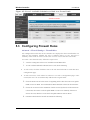
5.3
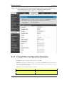
Configuring Firewall Rules ..................................................................................... 99
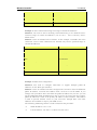
5.3.1 Firewall Rule Configuration Examples ............................................................... 103
5.4
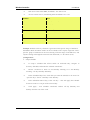
Security on Custom Services .............................................................................. 107
5.5
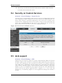
ALG support ........................................................................................................... 107
5.6
VPN Passthrough for Firewall ............................................................................. 108
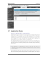
5.7
Application Rules .................................................................................................. 109
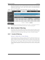
5.8
Web Content Filtering........................................................................................... 110
5.8.1 Content Filtering .................................................................................................... 110
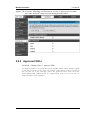
5.8.2 Approved URLs ..................................................................................................... 111
5.8.3 Blocked Keywords ................................................................................................ 112
5.8.4 Export Web Filter .................................................................................................. 113
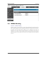
5.9
IP/MAC Binding ..................................................................................................... 114
5.10 Protecting from Internet Attacks ......................................................................... 115
Chapter 6. IPsec / PPTP / L2TP VPN ................................................................................................ 117
6.1
VPN Wizard ........................................................................................................... 119
6.2
Configuring IPsec Policies ................................................................................... 121
6.2.1 Extended Authentication (XAUTH) ..................................................................... 124
6.2.2 Internet over IPSec tunnel ................................................................................... 124
6.3
Configuring VPN clients ....................................................................................... 125
6.4
PPTP / L2TP Tunnels ........................................................................................... 125
6.4.1 PPTP Tunnel Support .......................................................................................... 125
6.4.2 L2TP Tunnel Support ........................................................................................... 127
6.4.3 OpenVPN Support ................................................................................................ 128
Chapter 7. SSL VPN ............................................................................................................................. 131
7.1
Groups and Users ................................................................................................. 133
7.1.1 Users and Passwords .......................................................................................... 139
7.2
Using SSL VPN Policies ...................................................................................... 140
7.2.1 Using Network Resources ................................................................................... 143
7.3
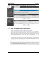
Application Port Forwarding ................................................................................ 144
7.4
SSL VPN Client Configuration ............................................................................ 146
7.4.1 Creating Portal Layouts ....................................................................................... 148
Chapter 8. Advanced Configuration Tools ......................................................................................... 151
8.1
USB Device Setup ................................................................................................ 151
8.2
Authentication Certificates ................................................................................... 152
8.3
WIDS Security ....................................................................................................... 154
3
Wireless Controller
8.3.1
8.3.2
User Manual
WIDS AP configration ............................................................................................ 154
WIDS Client Configuration..................................................................................... 157
Chapter 9. Administration & Management ......................................................................................... 161
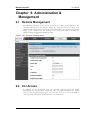
9.1
Remote Management ........................................................................................... 161
9.2
CLI Access ............................................................................................................. 161
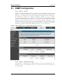
9.3
SNMP Configuration ............................................................................................. 162
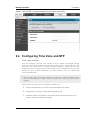
9.4
Configuring Time Zone and NTP ........................................................................ 163
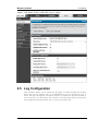
9.5
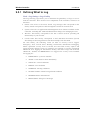
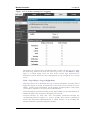
Log Configuration .................................................................................................. 164
9.5.1 Defining What to Log ............................................................................................ 165
9.5.2 Sending Logs to E-mail or Syslog ...................................................................... 168
9.5.3 Event Log Viewer in GUI ..................................................................................... 171
9.6
Backing up and Restoring Configuration Settings ........................................... 172
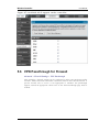
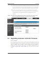
9.7
Upgrading wirelesss controller Firmware .......................................................... 173
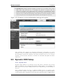
9.8
Dynamic DNS Setup............................................................................................. 174
9.9
Using Diagnostic Tools ........................................................................................ 175
9.9.1 Ping ......................................................................................................................... 176
9.9.2 Trace Route ........................................................................................................... 176
9.9.3 DNS Lookup .......................................................................................................... 176
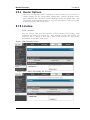
9.9.4 Router Options ...................................................................................................... 177
9.10 License ................................................................................................................... 177
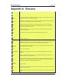
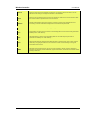
Appendix A. Glossary .............................................................................................................................. 178
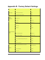
Appendix B. Factory Default Settings ................................................................................................... 180
4
Wireless Controller
User Manual
List of Figures
Figure 1: Setup page for LAN TCP/IP settings ...................................................................................... 13
Figure 2: IPv6 LAN and DHCPv6 configuration ..................................................................................... 15
Figure 3: Configuring the Router Advertisement Daemon ................................................................... 18
Figure 4: IPv6 Advertisement Prefix settings ......................................................................................... 19
Figure 5: Adding VLAN memberships to the LAN ................................................................................. 20
Figure 6: Port VLAN list ............................................................................................................................. 21
Figure 7: Configuring VLAN membership for a port .............................................................................. 22
Figure 8: DMZ configuration ..................................................................................................................... 23
Figure 9: UPnP Configuration ................................................................................................................... 24
Figure 10: Active Runtime sessions ........................................................................................................ 25
Figure 11: WLAN global configuration ..................................................................................................... 26
Figure 12: Configuring the Wireless Discovery ...................................................................................... 29
Figure 13: Wireless Discovery status ...................................................................................................... 30
Figure 14: AP Profile Global Configuration ............................................................................................. 31
Figure 15: AP Profile List ........................................................................................................................... 33
Figure 16: Internet Connection Setup Wizard ........................................................................................ 35
Figure 17: Manual Option1 configuration ................................................................................................ 38
Figure 18: PPPoE configuration for standard ISPs ............................................................................... 39
Figure 19: Option1 configuration for Japanese Multiple PPPoE (part 1) ........................................... 40
Figure 20: Option1 configuration for Multiple PPPoE (part 2) .............................................................. 41
Figure 21: Russia L2TP ISP configuration .............................................................................................. 42
Figure 22: IPv6 WAN Setup page ............................................................................................................ 43
Figure 23: Connection Status information of Option1 ........................................................................... 45
Figure 24: Load Balancing is available when multiple WAN ports are configured and Protocol
Bindings have been defined ................................................................................................... 48
Figure 25: Protocol binding setup to associate a service and/or LAN source to a WAN and/or
destination network .................................................................................................................. 49
Figure 26: Routing Mode is used to configure traffic routing between WAN and LAN, as well as
Dynamic routing (RIP) ............................................................................................................. 51
Figure 27: Static route configuration fields ............................................................................................. 54
Figure 28: Physical WAN port settings .................................................................................................... 55
Figure 29: Device Status display .............................................................................................................. 57
Figure 30: Device Status display (continued) ......................................................................................... 58
Figure 31: Resource Utilization statistics ................................................................................................ 59
Figure 32: Resource Utilization data (continued) ................................................................................... 59
5
Wireless Controller
User Manual
Figure 33: Physical port statistics ............................................................................................................. 61
Figure 34: List of current Active Firewall Sessions ................................................................................ 62
Figure 35: List of LAN hosts ...................................................................................................................... 63
Figure 36: List of current Active VPN Sessions ..................................................................................... 64
Figure 37: AP status ................................................................................................................................... 65
Figure 38: Managed AP status ................................................................................................................. 67
Figure 39: AP RF Scan Status.................................................................................................................. 69
Figure 40: Peer Controller Status ............................................................................................................. 70
Figure 41: Peer Controller Configuration Status .................................................................................... 71
Figure 42: Peer Controller Managed AP Status ..................................................................................... 72
Figure 43: Configuration Receive Status ................................................................................................ 74
Figure 44: Associated Client Status ......................................................................................................... 75
Figure 45: Associated Client SSID Status .............................................................................................. 76
Figure 46: Associated Client VAP Status ................................................................................................ 77
Figure 47: Controller Associated Client Status ...................................................................................... 78
Figure 48: Detected Client Status ............................................................................................................ 79
Figure 49: Pre-Auth History....................................................................................................................... 81
Figure 50: Detected Client Roam History ............................................................................................... 82
Figure 51: Valid Access Point Configuration .......................................................................................... 83
Figure 52: Add a Valid Access Point ....................................................................................................... 84
Figure 53: RF configuration ....................................................................................................................... 87
Figure 54: Channel Plan History .............................................................................................................. 89
Figure 55: Manual Channel Plan .............................................................................................................. 90
Figure 56: Manual Power Adjustment Plan ............................................................................................ 92
Figure 57: Access Point Software Download ......................................................................................... 93
Figure 58: Local OUI Database ................................................................................................................ 94
Fi gu r e 5 9 : M an a ge d A P S t at is t ic s ............................................................................................... 95
Figure 60: WLAN Associated Clients ...................................................................................................... 96
Figure 61: List of Available Firewall Rules .............................................................................................. 98
Figure 62: List of Available Schedules to bind to a firewall rule .......................................................... 99
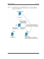
Figure 63: Example where an outbound SNAT rule is used to map an external IP address
(209.156.200.225) to a private DMZ IP address (10.30.30.30) ...................................... 102
Figure 64: The firewall rule configuration page allows you to define the To/From zone, service,
action, schedules, and specify source/destination IP addresses as needed. ............... 103
Figure 65: Schedule configuration for the above example. ................................................................ 106
Figure 66: List of user defined services. ............................................................................................... 107
6
Wireless Controller
User Manual
Figure 67: Available ALG support on the controller............................................................................. 108
Figure 68: Passthrough options for VPN tunnels ................................................................................. 109
Figure 69: List of Available Application Rules showing 4 unique rules ............................................ 110
Figure 70: Content Filtering used to block access to proxy servers and prevent ActiveX controls
from being downloaded ......................................................................................................... 111
Figure 71: Two trusted domains added to the Approved URLs List ................................................. 112
Figure 72: One keyword added to the block list ................................................................................... 113
Figure 73: Export Approved URL list ..................................................................................................... 114
Figure 74: The following example binds a LAN host’s MAC Address to an IP address served by
DWC-1000. If there is an IP/MAC Binding violation, the violating packet will be dropped
and logs will be captured ...................................................................................................... 115
Figure 75: Protecting the controller and LAN from internet attacks .................................................. 116
Figure 76: Example of Gateway-to-Gateway IPsec VPN tunnel using two DWC controllers
connected to the Internet ...................................................................................................... 117
Figure 77: Example of three IPsec client connections to the internal network through the DWC
IPsec gateway ........................................................................................................................ 118
Figure 78: VPN Wizard launch screen .................................................................................................. 119
Figure 79: IPsec policy configuration ..................................................................................................... 122
Figure 80: IPsec policy configuration continued (Auto policy via IKE).............................................. 123
Figure 81: IPsec policy configuration continued (Auto / Manual Phase 2) ...................................... 124
Figure 82: PPTP tunnel configuration – PPTP Client.......................................................................... 126
Figure 83: PPTP VPN connection status .............................................................................................. 126
Figure 84: PPTP tunnel configuration – PPTP Server ........................................................................ 127
Figure 85: L2TP tunnel configuration – L2TP Server .......................................................................... 128
Figure 86: OpenVPN configuration ........................................................................................................ 130
Figure 87: Example of clientless SSL VPN connections to the DWC-1000..................................... 132
Figure 88: List of groups .......................................................................................................................... 133
Figure 89: User group configuration ...................................................................................................... 134
Figure 90: SSLVPN Settings ................................................................................................................... 135
Figure 91: Group login policies options ................................................................................................. 136
Figure 92: Browser policies options ....................................................................................................... 137
Figure 93: IP policies options .................................................................................................................. 138
Figure 94: Available Users with login status and associated Group ................................................. 139
Figure 95: User configuration options .................................................................................................... 140
Figure 96: List of SSL VPN polices (Global filter) ................................................................................ 141
Figure 97: SSL VPN policy configuration .............................................................................................. 142
Figure 98: List of configured resources, which are available to assign to SSL VPN policies ....... 144
7
Wireless Controller
User Manual
Figure 99: List of Available Applications for SSL Port Forwarding .................................................... 146
Figure 100: SSL VPN client adapter and access configuration ......................................................... 147
Figure 101: Configured client routes only apply in split tunnel mode ............................................... 148
Figure 102: SSL VPN Portal configuration ........................................................................................... 150
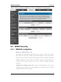
Figure 103: USB Device Detection ........................................................................................................ 152
Figure 104: Certificate summary for IPsec and HTTPS management ............................................. 154
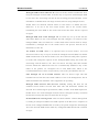
Fi gu r e 1 0 5: W IDS A P Co nf i g ura t io n ......................................................................................... 157
Figure 106: WIDS Client Configuration ................................................................................................. 160
Figure 107: Remote Management ......................................................................................................... 161
Figure 108: SNMP Users, Traps, and Access Control ........................................................................ 162
Figure 109: SNMP system information for this controller ................................................................... 163
Figure 110: Date, Time, and NTP server setup ................................................................................... 164
Figure 111: Facility settings for Logging ............................................................................................... 166
Figure 112: Log configuration options for traffic through controller ................................................... 168
Figure 113: E-mail configuration as a Remote Logging option .......................................................... 170
Figure 114: Syslog server configuration for Remote Logging (continued) ....................................... 171
Figure 115: VPN logs displayed in GUI event viewer ......................................................................... 172
Figure 116: Restoring configuration from a saved file will result in the current configuration being
overwritten and a reboot ....................................................................................................... 173
Figure 117: Firmware version information and upgrade option ......................................................... 174
Figure 118: Dynamic DNS configuration ............................................................................................... 175
Figure 119: Controller diagnostics tools available in the GUI ............................................................ 176
Figure 120: Install License ...................................................................................................................... 177
. Figure 121: After activating the License .............................................................................................. 177
8
Wireless Controller
User Manual
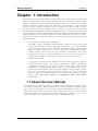
Chapter 1. Introduction
D-Link Wireless Controller (DWC), DWC-1000, is a full-featured wireless LAN
controller designing for small network environment. The centralized control function
contains various access point management functions, such as fast -roaming, inter-subnet
roaming, automatic channel and power adjustment, self -healing etc. The advanced
wireless security function, including rouge AP detection, captive portal, wireless
intrusion detection system (WIDS), offers a strong wireless network protection
avoiding attacks from hackers. Optimal network security is provided via features such
as virtual private network (VPN) tunnels, IP Security (IPsec), Point -to-Point Tunneling
Protocol (PPTP), Layer 2 Tunneling Protocol (L2TP), and Secure Sockets Layer (SSL).
Empower your road warriors with clientless remote access anywhere and anytime using
SSL VPN tunnels.
Comprehensive Management Capabilities
The DWC include dual-WAN Gigabit Ethernet which provides policy-based
service management ensuring maximum productivity for your business
operations. The failover feature maintains data traffic without disconnecting
when a landline connection is lost. The Outbound Load Balancing feature
adjusts outgoing traffic across two WAN interfaces and optimizes the system
performance resulting in high availabil ity. The second WAN port can be
configured as a DMZ port allowing you to isolate servers from your LAN.
Robust VPN features
A fully featured virtual private network (VPN) provides your mobile workers
and branch offices with a secure link to your network. DWC is capable of
simultaneously managing 20 Secure Sockets Layer (SSL) VPN tunnels
respectively, empowering your mobile users by providing remote access to a
central corporate database. Site-to-site VPN tunnels use IP Security (IPsec)
Protocol, Point-to-Point Tunneling Protocol (PPTP), or Layer 2 Tunneling
Protocol (L2TP) to facilitate branch office connectivity through encrypted
virtual links. The DWC support 75 simultaneous IPSec VPN tunnels
respectively.
1.1 About this User Manual
This document is a high level manual to allow new D-Link Wireless Controller users
to configure connectivity, WLAN configuration, setup VPN tunnels, establish firewall
rules and AP management and perform general administrative tasks. Typical
deployment and use case scenarios are described in each section. For more detailed
setup instructions and explanations of each configuration parameter, refer to the
online help that can be accessed from each page in the controller GUI.
9
Wireless Controller
User Manual
1.2 Typographical Conventions
The following is a list of the various terms, followed by an example of how that term
is represented in this document:
Product Name – D-Link Wireless Controller.
o Model numbers DWC-1000
GUI Menu Path/GUI Navigation – Monitoring > Controller Status
Important note –
10
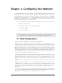
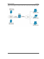
Chapter 2. Configuring Your Network:
It is assumed that the user has a machine for management connected to the LAN to the
controller. The LAN connection may be through the wired Ethernet ports available on
the controller, or once the initial setup is complete, the DWC may also be managed
through its wireless interface as it is bridged with the LAN. Access the controller‘s
graphical user interface (GUI) for management by using any web browser, such as
Microsoft Internet Explorer or Mozilla Firefox:
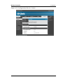
Go to http://192.168.10.1 (default IP address) to display the controller‘s
management login screen.
Default login credentials for the management GUI:
Username: admin
Password: admin
If the controller‘s LAN IP address was changed, use that IP address in the
navigation bar of the browser to access the controller‘s management UI.
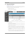
2.1 LAN Configuration
Setup > Network Settings > LAN Setup Configuration
By default, the controller functions as a Dynamic Host Configuration Protocol
(DHCP) server to the hosts on the WLAN or LAN network. With DHCP, PCs and
other LAN devices can be assigned IP addresses as well as addresses for DNS servers,
Windows Internet Name Service (WINS) servers, and the default gatewa y. With the
DHCP server enabled the controller‘s IP address serves as the gateway address for
LAN and WLAN clients. The PCs in the LAN are assigned IP addresses from a pool
of addresses specified in this procedure. Each pool address is tested before it is
assigned to avoid duplicate addresses on the LAN.
For most applications the default DHCP and TCP/IP settings are satisfactory. If you
want another PC on your network to be the DHCP server or if you are manually
configuring the network settings of all of yo ur PCs, set the DHCP mode to ‗none‘.
DHCP relay can be used to forward DHCP lease information from another LAN
device that is the network‘s DHCP server; this is particularly useful for wireless
clients.
Instead of using a DNS server, you can use a Windows Internet Naming Service
(WINS) server. A WINS server is the equivalent of a DNS server but uses the
NetBIOS protocol to resolve hostnames. The controller includes the WINS server IP
address in the DHCP configuration when acknowledging a DHCP request from a
DHCP client.
You can also enable DNS proxy for the LAN. When this is enabled the controller then
as a proxy for all DNS requests and communicates with the ISP‘s DNS servers. When
disabled all DHCP clients receive the DNS IP addresses of the ISP.
Wireless Controller
User Manual
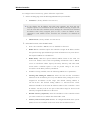
To configure LAN Connectivity, please follow the steps below:
1. In the LAN Setup page, enter the following information for your controller:
IP address: (factory default: 192.168.10.1).
If you change the IP address and click Save Settings, the GUI will not
respond. Open a new connection to the new IP address and log in again. Be
sure the LAN host (the machine used to manage the controller) has obtained
IP address from newly assigned pool (or has a static IP address in the
controller‘s LAN subnet) before accessing the controller via changed IP
address.
Subnet mask: (factory default: 255.255.255.0).
2. In the DHCP section, select the DHCP mode:
None: the controller‘s DHCP server is disabled for the LAN
DHCP Server. With this option the controller assigns an IP address within
the specified range plus additional specified information to any LAN device
that requests DHCP served addresses.
DHCP Relay: With this option enabled, DHCP clients on the LAN can
receive IP address leases and corresponding information from a DHCP
server on a different subnet. Specify the Relay Gateway, and when LAN
clients make a DHCP request it will be passed along to the server
accessible via the Relay Gateway IP address.
If DHCP is being enabled, enter the following DHCP server parameters:
Starting and Ending IP Addresses: Enter the first and last continuous
addresses in the IP address pool. Any new DHCP client joining the LAN is
assigned an IP address in this range. The default starting address is
192.168.10.100. The default ending address is 192.168.10.254. These
addresses should be in the same IP address subnet as the controller‘s LAN
IP address. You may wish to save part of the subnet range for devices with
statically assigned IP addresses in the LAN.
Default Gateway (Optional): Enter the IP address of the controller which
you want to make it as a default other than DWC -1000
Primary and Secondary DNS servers: If configured domain name system
(DNS) servers are available on the LAN enter their IP addresses here.
12
Wireless Controller
User Manual
Domain Name: Enter domain name
WINS Server (optional): Enter the IP address for the WINS server or, if
present in your network, the Windows NetBios server.
Lease Time: Enter the time, in hours, for which IP addresses are leased to
clients.
Enable DNS Proxy: To enable the controller to act as a proxy for all DNS
requests and communicate with the ISP‘s DNS servers, click the checkbox.
Relay Gateway: Enter the gateway address. This is the only configuration
parameter required in this section when DHCP Relay is selected as its
DHCP mode
3. Click Save Settings to apply all changes.
Figure 1: Setup page for LAN TCP/IP settings
13
Wireless Controller
User Manual
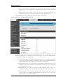
2.1.1 LAN Configuration in an IPv6 Network
Advanced > IPv6 > IPv6 LAN > IPv6 LAN Config
In IPv6 mode, the LAN DHCP server is enabled by default (similar to IP v4 mode).
The DHCPv6 server will serve IPv6 addresses from configured address pools with
the IPv6 Prefix Length assigned to the LAN.
IPv4 / IPv6 mode must be enabled in the Advanced > IPv6 > Routing mode to
enable IPv6 configuration options.
LAN Settings
The default IPv6 LAN address for the router is fec0::1. You can change this 128 bit
IPv6 address based on your network requirements. The other field that defines the
LAN settings for the router is the prefix length. The IPv6 network (subnet) is
identified by the initial bits of the address called the prefix. By default this is 64
bits long. All hosts in the network have common initial bits for their IPv6 address;
the number of common initial bits in the network‘s addresses is set by the prefix
length field.
14
Wireless Controller
User Manual
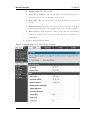
Figure 2: IPv6 LAN and DHCPv6 configuration
If you change the IP address and click Save Settings, the GUI will not respond.
Open a new connection to the new IP address and log in again. Be sure the LAN
host (the machine used to manage the router) has obtained IP address from newly
assigned pool (or has a static IP address in the router‘s LAN subnet) before
accessing the router via changed IP address.
As with an IPv4 LAN network, the router has a DHCPv6 server. If enabled, the
router assigns an IP address within the specified range plus additional specified
information to any LAN PC that requests DHCP served addresses.
15
Wireless Controller
User Manual
The following settings are used to configure the DHCPv6 server:
DHCP Mode: The IPv6 DHCP server is either state less or stateful. If stateless is
selected an external IPv6 DHCP server is not required as the IPv6 LAN hosts
are auto-configured by this controller. In this case the controller advertisement
daemon (RADVD) must be configured on this device and ICMPv6 controller
discovery messages are used by the host for auto -configuration. There are no
managed addresses to serve the LAN nodes. If stateful is selected the IPv6 LAN
host will rely on an external DHCPv6 server to provide required configuration
settings
The domain name of the DHCPv6 server is an optional setting
Server Preference is used to indicate the preference level of this DHCP server.
DHCP advertise messages with the highest server preference value to a LAN
host are preferred over other DHCP server advertise messages . The default is
255.
The DNS server details can be manually entered here (primary/secondary
options. An alternative is to allow the LAN DHCP client to receive the DNS
server details from the ISP directly. By selecting Use DNS proxy, this router
acts as a proxy for all DNS requests and communicates with the ISP‘s DNS
servers (a WAN configuration parameter).
Primary and Secondary DNS servers: If there are configured domain name
system (DNS) servers available on the LAN enter the IP addresses here.
Lease/Rebind time sets the duration of the DHCPv6 lease from this router to the
LAN client.
IPv6 Address Pools
This feature allows you to define the IPv6 delegation prefix for a range of IP
addresses to be served by the gateway‘s DHCPv6 server. Using a delegation p refix
you can automate the process of informing other networking equipment on the LAN
of DHCP information specific for the assigned prefix.
Prefix Delegation
The following settings are used to configure the Prefix Delegation:
Prefix Delegation: Select this option to enable prefix delegation in DHCPv6
server. This option can be selected only in Stateless Address Auto
Configuration mode of DHCPv6 server.
Prefix Address: IPv6 prefix address in the DHCPv6 server prefix pool
Prefix Length: Length prefix address
16
Wireless Controller
User Manual
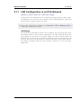
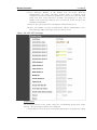
2.1.2 Configuring IPv6 Router Advertisements
Router Advertisements are analogous to IPv4 DHCP assignments for LAN clients, in
that the router will assign an IP address and supporting network information to
devices that are configured to accept such details. Rout er Advertisement is required
in an IPv6 network is required for stateless auto configuration of the IPv6 LAN. By
configuring the Router Advertisement Daemon on this router, the DWC-1000 will
listen on the LAN for router solicitations and respond to these L AN hosts with
router advisements.
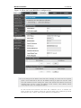
RADVD
Advanced > IPv6 > IPv6 LAN > Router Advertisement
To support stateless IPv6 auto configuration on the LAN, set the RADVD status to
Enable. The following settings are used to configure RADVD:
Advertise Mode: Select Unsolicited Multicast to send router advertisements
(RA‘s) to all interfaces in the multicast group. To restrict RA‘s to well
known IPv6 addresses on the LAN, and thereby reduce overall network
traffic, select Unicast only.
Advertise Interval: When advertisements are unsolicited multicast packets,
this interval sets the maximum time between advertisements from the
interface. The actual duration between advertisements is a random value
between one third of this field and this field. The default is 30 seconds.
RA Flags: The router advertisements (RA‘s) can be sent with one or both of
these flags. Chose Managed to use the administered /stateful protocol for
address auto configuration. If the Other flag is selected the host uses
administered/stateful protocol for non-address auto configuration.
Router
Preference:
this
low/medium/high
parameter
determines
the
preference associated with the RADVD process of the router. This is useful
if there are other RADVD enabled devices on the LAN as it helps avoid
conflicts for IPv6 clients.
MTU: The router advertisement will set this maximum transmission unit
(MTU) value for all nodes in the LAN that are autoconfigured by the router.
The default is 1500.
Router Lifetime: This value is present in RA‘s and indicates the usefulnes s
of this router as a default router for the interface. The default is 3600
seconds. Upon expiration of this value, a new RADVD exchange must take
place between the host and this router.
17
Wireless Controller
User Manual
Figure 3: Configuring the Router Advertisem ent Daemon
Advertisement Prefixes
Advanced > IPv6 > IPv6 LAN > Advertisement Prefixes
The router advertisements configured with advertisement prefixes allow this router
to inform hosts how to perform stateless address auto configuration. Router
advertisements contain a list of subnet prefixes that allow the router to determine
neighbors and whether the host is on the same link as the router.
The following prefix options are available for the router advertisements:
IPv6 Prefix Type: To ensure hosts support IPv6 to IPv4 tunnel select the
6to4 prefix type. Selecting Global/Local/ISATAP will allow the nodes to
support all other IPv6 routing options
SLA ID: The SLA ID (Site-Level Aggregation Identifier) is available when
6to4 Prefixes are selected. This should be the interface ID of the router‘s
LAN interface used for router advertisements.
IPv6 Prefix: When using Global/Local/ISATAP prefixes, this field is used to
define the IPv6 network advertised by this router.
18
Wireless Controller
User Manual
IPv6 Prefix Length: This value indicates the number contiguous, higher
order bits of the IPv6 address that define up the network portion of the
address. Typically this is 64.
Prefix Lifetime: This defines the duration (in seconds) that the requesting
node is allowed to use the advertised prefix. It is analogous to DHCP lease
time in an IPv4 network.
Figure 4: IPv6 Advertisement Prefix settings
2.2 VLAN Configuration
The controller supports virtual network isolation on the LAN with the use of VLANs.
LAN devices can be configured to communicate in a subnetwork defined by VLAN
identifiers. LAN ports can be assigned unique VLAN IDs so that traffic to and from
that physical port can be isolated from the general LAN. VLAN filtering is
particularly useful to limit broadcast packets of a device in a large network
VLAN support is disabled by default in the controller. In the VLAN Configuration
page, enable VLAN support on the controller and then proceed to the next section to
define the virtual network.
Setup > VLAN Settings > Available VLAN
The Available VLAN page shows a list of configured VLANs by name and VLAN ID.
A VLAN membership can be created by clicking the Add button below the List of
Available VLANs.
A VLAN membership entry consists of a VLAN identifier and the numerical VLAN
ID which is assigned to the VLAN membership. The VLAN ID value can be any
number from 2 to 4091. VLAN ID 1 is reserved for the default VLAN, which is used
for untagged frames received on the interface. By enabling Inter VLAN Routing, you
19
Wireless Controller
User Manual
will allow traffic from LAN hosts belonging to this VLAN ID to pass through to other
configured VLAN IDs that have Inter VLAN Routing enabled.
Figure 5: Adding VLAN memberships to the LAN
2.2.1 Associating VLANs to ports
In order to tag all traffic through a specific LAN port with a VLAN ID, you can
associate a VLAN to a physical port.
Setup > VLAN Settings > Port VLAN
VLAN membership properties for the LAN and wireless LAN are listed on this page.
The VLAN Port table displays the port identifier, the mode setting for that port and
VLAN membership information. The configuration page is accessed by selecting
one of the four physical ports or a configured access point and clicking Edit.
The edit page offers the following configuration options:
Mode: The mode of this VLAN can be General, Access, or Trunk. The
default is access.
In General mode the port is a member of a user selectable set of VLANs.
The port sends and receives data that is tagged or untagged with a VLAN
ID. If the data into the port is untagged, it is assigned the defined PVID. In
the configuration from Figure 4, Port 3 is a General port with PVID 3, so
untagged data into Port 3 will be assigned PVID 3. All tagged data sent out
of the port with the same PVID will be untagged. This is mode is typically
used with IP Phones that have dual Ethernet ports. Data coming from phone
20
Wireless Controller
User Manual
to the switch port on the controller will be tagged. Data passing through the
phone from a connected device will be untagged.
Figure 6: Port VLAN list
In Access mode the port is a member of a single VLAN (and only one). All
data going into and out of the port is untagged. Traffic through a port in
access mode looks like any other Ethernet frame.
In Trunk mode the port is a member of a user selectable set of VLANs. All
data going into and out of the port is tagged. Untagged coming into the port
is not forwarded, except for the default VLAN with PVID=1, which is
untagged. Trunk ports multiplex traffic for multiple VLANs over the s ame
physical link.
Select PVID for the port when the General mode is selected.
Configured
VLAN
memberships
will
be
displayed
on
the
VLAN
Membership Configuration for the port. By selecting one more VLAN
membership options for a General or Trunk port, traf fic can be routed
between the selected VLAN membership IDs
21
Wireless Controller
User Manual
Figure 7: Configuring VLAN membership for a port
2.3 Configurable Port: DMZ Setup
This controller supports one of the physical ports to be configured as a secondary
WAN Ethernet port or a dedicated DMZ port. A DMZ is a subnetwork that is open to
the public but behind the firewall. The DMZ adds an additional layer of security to
the LAN, as specific services/ports that are exposed to the internet on the DMZ do not
have to be exposed on the LAN. It is recommended that hosts that must be exposed to
the internet (such as web or email servers) be placed in the DMZ network. Firewall
rules can be allowed to permit access specific services/ports to the DMZ from both
the LAN or WAN. In the event of an attack to any of the DMZ nodes, the LAN is not
necessarily vulnerable as well.
Setup > DMZ Setup > DMZ Setup Configuration
DMZ configuration is identical to the LAN configuration. There are no restrictions on
the IP address or subnet assigned to the DMZ port, other than the fact that it cannot
be identical to the IP address given to the LAN interface of this gateway.
22
Wireless Controller
User Manual
Figure 8: DMZ configuration
In order to configure a DMZ port, the controller configurable port must be set to
DMZ in the Setup > Internet Settings > Configurable Port page.
2.4 Universal Plug and Play (UPnP)
Advanced > Advanced Network > UPnP
Universal Plug and Play (UPnP) is a feature that allows the controller to discovery
devices on the network that can communicate with the controller and allow for auto
configuration. If a network device is detected by UPnP, the controller can open
internal or external ports for the traffic protocol required by that network device.
Once UPnP is enabled, you can configure the controller to detect UPnP-supporting
devices on the LAN (or a configured VLAN). If disabled, the controller will not allow
for automatic device configuration.
Configure the following settings to use UPnP:
23
Wireless Controller
User Manual
Advertisement Period: This is the frequency that the controller broadcasts UPnP
information over the network. A large value will minimize network traffic but
cause delays in identifying new UPnP devices to the network.
Advertisement Time to Live: This is expressed in hops for each UPnP packet. This
is the number of steps a packet is allowed to propagate before being discarded.
Small values will limit the UPnP broadcast range. A default of 4 is typical for
networks with few switches.
Figure 9: UPnP Configuration
UPnP Port map Table
The UPnP Port map Table has the details of UPnP devices that respond to the
controller advertisements. The following information is displayed for each detected
device:
Active: A yes/no indicating whether the port of the UPnP device that established a
connection is currently active
Protocol: The network protocol (i.e. HTTP, FTP, etc.) used by the DWC
Int. Port (Internal Port): The internal ports opened by UPnP (if any)
Ext. Port (External Port): The external ports opened by UPnP (if any)
IP Address: The IP address of the UPnP device detected by this controller
Click Refresh to refresh the portmap table and search for any new UPnP devices
24
Wireless Controller
User Manual
2.5 Captive Portal
LAN users can gain internet access via web portal authentication with the DWC.
Also referred to as Run-Time Authentication, a Captive Portal is ideal for a web
café scenario where users initiate HTTP connection requests for web access but are
not interested in accessing any LAN services. Firewall policies underneath will
define which users require authentication for HTTP access, and when a matching
user request is made the DWC will intercept the request and prompt for a username /
password. The login credentials are compared against the RunTimeAuth users in
user database prior to granting HTTP access.
Captive Portal is available for LAN users only and not for DM Z hosts.
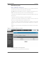
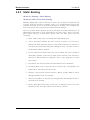
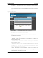
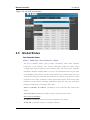
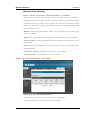
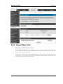
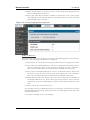
Advanced > Captive Portal >Captive Portal Sessions
The Active Runtime internet sessions through the controller firewall are listed in the
below table. These users are present in the local or external user database and have
had their login credentials approved for internet access. A ‗Disconnect‘ button
allows the DWC-1000 admin to selectively drop an authenticated user.
Figure 10: Active Runtime sessions
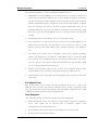
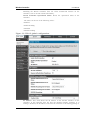
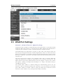
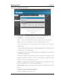
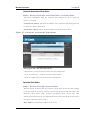
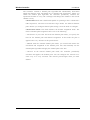
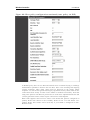
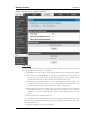
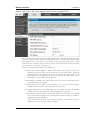
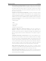
2.6 WLAN global configuration
Setup > WLAN Global Settings
Following are the options available to enable the WLAN function on DWC -1000
Enable WLAN Controller:
Select this option to enable WLAN controller
functionality on the system. Clear the option to administratively disable the WLAN
controller. If you clear the option, all peer controller and APs that are associated
with this controller are disassociated.
25
Wireless Controller
User Manual
Disabling the WLAN controller does not affect non-WLAN features on the
controller, such as VLAN or STP functionality.
WLAN Controller Operational Status: Shows the operational status of the
controller
. The status can be one of the following values:
• Enabled
• Enable-Pending
• Disabled
• Disable-Pending
Figure 11: WLAN global configuration
IP Address: This field shows the IP address of the WLAN interface on the
controller. If the controller does not have the Routing Package installed, or if
routing is disabled, the IP address is the network interface. If the routing package is
26
Wireless Controller
User Manual
installed and enabled, this is the IP address of the routing or loo pback interface you
configure for the controller features.
AP MAC Validation Method: Add the MAC address of the AP to the Valid AP
database, which can be kept locally on the controller or in an external RADIUS
server. When the controller discovers an AP that is not managed by another
ccontroller, it looks up the MAC address of the AP in the Valid AP database. If it
finds the MAC address in the database, the controller validates the AP and assumes
management. Select the database to use for AP validation and , optionally, for
authentication if the Require Authentication Passphrase option is selected.
• Local: If you select this option, you must add the MAC address of each AP to the
local Valid AP database.
• RADIUS: If you select this option, you must configur e the MAC address of each
AP in an external RADIUS server.
Require Authentication Passphrase: Select this option to require APs to be
authenticated before they can associate with the controller. If you select this option,
you must configure the passphrase on the AP while it is in standalone mode as well
as in the Valid AP database.
RADIUS Authentication Server Name : Enter the name of the RADIUS server used
for AP and client authentications. The name can contain up to 32 alphanumeric
characters. Spaces, underscores, and dashes are also permitted. The controller acts
as the RADIUS client and performs all RADIUS transactions on behalf of the APs
and wireless clients.
RADIUS Authentication Server Configured: Indicates whether the RADIUS
authentication server is configured.
RADIUS Accounting Server Name: Enter the name of the RADIUS server used for
reporting wireless client associations and disassociations. The name can contain up
to 32 alphanumeric characters. Spaces, underscores, and dashes are also permitted.
RADIUS Accounting Server
accounting server is configured.
Configured:
Indicates
whether
the
RADIUS
RADIUS Accounting: Select this option to enable RADIUS accounting for wireless
clients.
Country Code: Select the country code that represents the country w here your
controller and APs operate. When you click Submit, a pop -up message asks you to
confirm the change. Wireless regulations vary from country to country. Make sure
you select the correct country code so that your WLAN system complies with the
regulations in your country.
27
Wireless Controller
User Manual
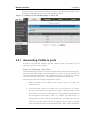
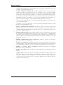
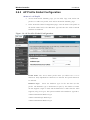
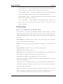
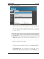
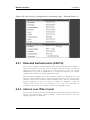
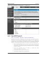
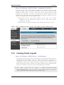
2.6.1 Wireless Discovery configuration
The wireless controller can discover, validate, authenticate, or monitor the
following system devices:
• Peer wireless controllers
• APs
• Wireless clients
• Rogue APs
• Rogue wireless clients
Setup > AP Management > Poll List
The wireless controller can discover peer wireless controller and APs
regardless of whether these devices are connected to each other, located in the
same Layer 2 broadcast domain, or attached to different IP subnets. In order for
the controller to discover other WLAN devices and establish communication
with them, the devices must have their own IP address, must be able to find
other WLAN devices, and must be compatible. When the controller discovers
and validates APs, the controller takes over the management of the AP. If you
configure the AP in Standalone mode, the existing AP configuration is replaced
by the default AP Profile configuration on the controller.
L3/IP Discovery: Select or clear this option to enable or disable IP -based
discovery of access points and peer wireless controller. When the L3/IP
Discovery option is selected, IP polling is enabled and the controller will
periodically poll each address in the configured IP List. By default, L3/IP
Discovery is enabled.
List of IP address: Shows the list of IP addresses configured for discovery.
To remove entries from the list, select one or more entries and click Delete.
Hold the "shift" key or ―control‖ key to select specific entry.
IP Address Range: This text field is used to add a range of IP address entries
to the IP List. Enter the IP address at the start of the address range in the From
field, and enter the IP address at the end of the range in the To field, then click
Add. All IP addresses in the range are added to th e IP List. Only the last octet
is allowed to differ between the From address and the To address.
28
Wireless Controller
User Manual
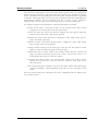
Figure 12: Configuring the Wireless Discovery
L2/VLAN Discovery: The D-Link Wireless Device Discovery Protocol is a
good discovery method to use if the controller and APs are located in the same
Layer 2 multicast domain. The wireless controller periodically sends a
multicast packet containing the discovery message on each VLAN enabled for
discovery
This page includes the following buttons:
• Add—Adds the data in the IP Address or VLAN field to the appropriate list.
• Delete—Deletes the selected entry from the IP or VLAN list.
29
Wireless Controller
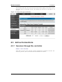
User Manual
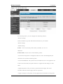
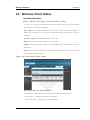
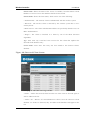
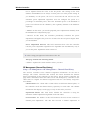
Wireless Discovery status
Status > Global Info > IP Discovery
The IP Discovery list can contain the IP addresses of peer controller and APs for
the UWS to discover and associate with as part of the WLAN
IP Address: Shows the IP address of the device configured in the IP Discovery list
Status: The wireless discovery status is in one of the following states:
• Not Polled: The controller has not attempted to contact the IP address in the L3/IP
Discovery list.
• Polled: The controller has attempted to contact the IP address.
• Discovered: The controller contacted the peer controller or the AP in the L3/IP
Discovery list and has authenticated or validated the device.
• Discovered - Failed: The controller contacted the peer controller or the AP with
IP address in the L3/IP Discovery list and was unable to authenticate or validate the
device.
If the device is an access point, an entry appears in the AP failure list with a failure
reason.
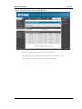
Figure 13: Wireless Discovery status
This page includes the following buttons:
• Refresh—Updates the page with the latest information
30
Wireless Controller
User Manual
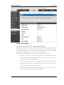
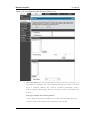
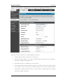
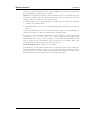
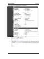
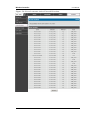
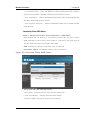
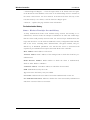
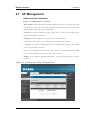
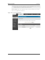
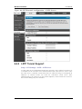
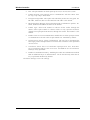
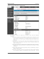
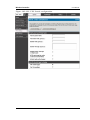
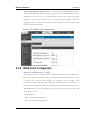
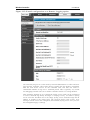
2.6.2 AP Profile Global Configuration
Advanced > AP Profile
Access Point Profile Summary page, you can Add, Copy, Edit, Delete AP
profiles. To add a new profile, click Add in AP Profile Summary page.
In the AP Profile Global Configuration page, enter the name of the profile in
the Profile Name field, select Hardware type and enter the valid VLAN ID
and then click Submit.
Figure 14: AP Profile Global Configuration
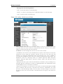
Profile Name: The Access Point profile name you added. Use 0 to 32
characters. Only alphanumeric characters are allowed. No special characters
are allowed.
Hardware Type:
Select the hardware type for the APs that use this
profile. The hardware type is determined, in part, by the number of radios
the AP supports (single or dual) and the IEEE 802.11 modes th at the radio
supports (a/b/g or a/b/g/n). The option available in the Hardware Type ID is:
• DWL-8600AP Dual Radio a/b/g/n
• DWL-3600AP Single Radio b/g/n
• DWL-6600AP Dual Radio a/b/g/n
31
Wireless Controller
User Manual
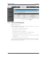
Wired Network Discovery VLAN ID: Enter the VLAN ID that the
controller uses to send tracer packets in order to detect APs connected to the
wired network.
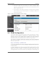
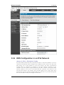
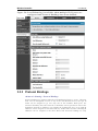
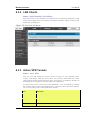
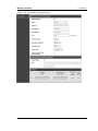
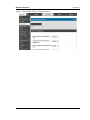
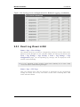
AP Profile
Advanced > AP Profile
Access point configuration profiles are a useful feature for large wireless
networks with APs that serve a variety of different use rs. You can create
multiple AP profiles on the
Controller to customize APs based on location,
function, or other criteria. Profiles are like templates, and once you create an AP
profile, you can apply that profile to any AP .
32
Wireless Controller
User Manual
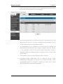
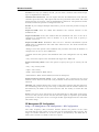
Figure 15: AP Profile List
For each AP profile, you can configure the following features:
• Profile settings
(Name, Hardware Type ID, Wired Network Discovery VLAN ID)
• Radio settings
• SSID settings
Profile: The Access Point profile name you added. Use 0 to 32
characters.
Profile Status: can have one of the following values:
• Associated: The profile is configured, and one or more APs managed by the
controller are associated with this profile.
• Associated-Modified: The profile has been modified s ince it was applied to one
or more associated APs; the profile must be re -applied for the changes to take
effect.
• Apply Requested: After you select a profile and click Apply, the screen
refreshes and shows that an apply has been requested.
• Apply In Progress: The profile is being applied to all APs that use this profile.
33
Wireless Controller
User Manual
During this process the APs reset, and all wireless clients are disassociated from
the AP.
• Configured: The profile is configured, but no APs managed by the controller
currently use this profile.
Associate a profile with an AP. Entry of the AP is valid and available in
database of the controller.
This page includes the following buttons:
• Edit— To edit the existing AP profile.
• Delete— To delete the existing AP profile.
• Add— Allows to add a new AP profile
• Copy— Allows to copy the existing AP profile.
• Apply— Update the AP profile configuration details entered .
• Configure Radio — Allows to configure the AP profile Radio configuration.
• Configure SSID — Allows to configure the AP profile VAP configuration.
34
Wireless Controller
User Manual
Chapter 3. Connecting to the Internet:
WAN Setup
This contoller has two WAN ports that can be used to establish a connection to the
internet. The following ISP connection types are supported: DHCP, Static, PPPoE,
PPTP, L2TP (via USB modem).
It is assumed that you have arranged for internet service with your Internet Service
Provider (ISP). Please contact your ISP or network administrator for the configuration
information that will be required to setup the controller.
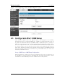
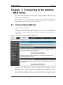
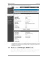
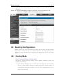
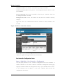
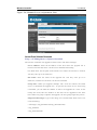
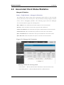
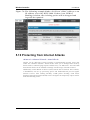
3.1 Internet Setup Wizard
Setup > Wizard > Internet
The Internet Connection Setup Wizard is available for users new to networking. By
going through a few straightforward configuration pages you can take the information
provided by your ISP to get your WAN connection up and enable internet access for
your network.
Figure 16: Internet Connection Setup Wizard
You can start using the Wizard by logging in with the administrator password for the
controller. Once authenticated set the time zone that you are located in, and then
choose the type of ISP connection type: DHCP, Static, PPPoE, PPTP, L2TP.
Depending on the connection type a username/password may be required to register
this controller with the ISP. In most cases the default settings can be used if the ISP
did not specify that parameter. The last step in the Wizard is to click the Connect
35
Wireless Controller
User Manual
button, which confirms the settings by establishing a link with the ISP. Once
connected, you can move on and configure other features in this controller.
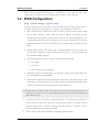
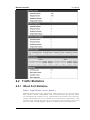
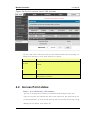
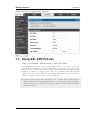
3.2 WAN Configuration
Setup > Internet Settings > Option1 Setup
You must either allow the controller to detect WAN connection type automatically or
configure manually the following basic settings to enable Internet connectivity:
ISP Connection type: Based on the ISP you have selected for the primary WAN
link for this controller, choose Static IP address, DHCP client, Point-to-Point
Tunneling Protocol (PPTP), Point -to-Point Protocol over Ethernet (PPPoE), Layer
2 Tunneling Protocol (L2TP). Required fields for the selected ISP type become
highlighted. Enter the following information as needed and as provided by your
ISP:
PPPoE Profile Name. This menu lists configured PPPoE profiles, particularly
useful when configuring multiple PPPoE connections (i.e. f or Japan ISPs that
have multiple PPPoE support).
ISP login information. This is required for PPTP and L2TP ISPs.
User Name
Password
Secret (required for L2TP only)
MPPE Encryption: For PPTP links, your ISP may require you to enable Microsoft
Point-to-Point Encryption (MPPE).
Split Tunnel (supported for PPTP and L2TP connection). This setting allows your
LAN hosts to access internet sites over this WAN link while still permitting VPN
traffic to be directed to a VPN configured on this WAN port.
If split tunnel is enabled, DWC won‘t expect a default route from the ISP server. In
such case, user has to take care of routing manually by configuring the routing from
Static Routing page.
Connectivity Type: To keep the connection always on, click Keep Connected. To
log out after the connection is idle for a period of time (useful if your ISP costs are
based on logon times), click Idle Timeout and enter the time, in minutes, to wait
before disconnecting in the Idle Time field.
My IP Address: Enter the IP address assigned to you by the ISP.
36
Wireless Controller
User Manual
Server IP Address: Enter the IP address of the PPTP or L2TP server.
3.2.1 WAN Port IP address
Your ISP assigns you an IP address that is either dynamic (newly generated each
time you log in) or static (permanent). The IP Address Source option allows you to
define whether the address is statically provided by the ISP or should be received
dynamically at each login. If static, enter your IP address, IPv4 subnet mask, and the
ISP gateway‘s IP address. PPTP and L2TP ISPs also can provide a static IP address
and subnet to configure, however the default is to receive that information
dynamically from the ISP.
3.2.2 WAN DNS Servers
The IP Addresses of WAN Domain Name Servers (DNS) are typically provided
dynamically from the ISP but in some cases you can define the static IP addresses of
the DNS servers. DNS servers map Internet domain names (example:
www.google.com) to IP addresses. Click to indicate whether to get DNS server
addresses automatically from your ISP or to use ISP -specified addresses. If its
latter, enter addresses for the primary and secondary DNS servers. To avoid
connectivity problems, ensure that you enter the addresses correctly.
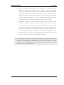
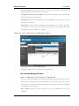
3.2.3 DHCP WAN
For DHCP client connections, you can choose the MAC address of the controller to
register with the ISP. In some cases you may need to clone the LAN host‘s MAC
address if the ISP is registered with that LAN host.
37
Wireless Controller
User Manual
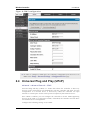
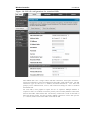
Figure 17: Manual Option1 configuration
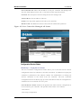
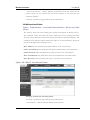
3.2.4 PPPoE
Setup > Internet Settings
The PPPoE ISP settings are defined on the WAN Configuration page. There are two
types of PPPoE ISP‘s supported by the DWC-1000: the standard username/password
PPPoE and Japan Multiple PPPoE.
38
Wireless Controller
User Manual
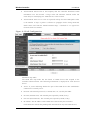
Figure 18: PPPoE configuration for standard ISPs
Most PPPoE ISP‘s use a single control and data connection, and require username /
password credentials to login and authenticate the DWC-1000 with the ISP. The ISP
connection type for this case is ―PPPoE (Username/Password)‖. The GUI will
prompt you for authentication, service, and connection settings in order to establish
the PPPoE link.
For some ISP‘s, most popular in Japan, the use of ―Japanese Multiple PPPoE‖ is
required in order to establish concurrent primary and secondary PPPoE connections
between the DWC-1000 and the ISP. The Primary connection is used for the bulk of
data and internet traffic and the Secondary PPPoE connection carries ISP specific
(i.e. control) traffic between the DWC-1000 and the ISP.
39
Wireless Controller
User Manual
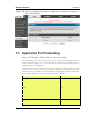
Figure 19: Option1 configuration for Japanese Multiple PPPoE (part 1)
There are a few key elements of a multiple PPPoE connection:
Primary and secondary connections are concurrent
Each session has a DNS server source for domain name lookup, this can be assigned by
the ISP or configured through the GUI
The DWC-1000 acts as a DNS proxy for LAN users
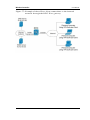
Only HTTP requests that specifically identify the secondary connection‘s domain name
(for example *.flets) will use the secondary profile to access the content available
through this secondary PPPoE terminal. All other HTTP / HTTPS requests go through
the primary PPPoE connection.
40
Wireless Controller
User Manual
When Japanese multiple PPPoE is configured and secondary connection is up, some predefined
routes are added on that interface. These routes are needed to access the internal domain of the
ISP where he hosts various services. These routes can even be configured through the static
routing page as well.
Figure 20: Option1 configuration for Multiple PPPoE (part 2)
3.2.5 Russia L2TP and PPTP WAN
For Russia L2TP WAN connections, you can choose the address mode of the
connection to get an IP address from the ISP or configure a static IP address
provided by the ISP. For DHCP client connections, you can choose the MAC
address of the controller to register with the ISP. In some cases you may need to
clone the LAN host‘s MAC address if the ISP is registered with that LAN host.
41
Wireless Controller
User Manual
Figure 21: Russia L2TP ISP configuration
3.2.6 WAN Configuration in an IPv6 Network
Advanced > IPv6 > IPv6 Option1 Config
For IPv6 WAN connections, this controller can have a static IPv6 address or receive
connection information when configured as a DHCPv6 client. In the case where the
ISP assigns you a fixed address to access the internet, the static configuratio n
settings must be completed. In addition to the IPv6 address assigned to your
controller, the IPv6 prefix length defined by the ISP is needed. The default IPv6
Gateway address is the server at the ISP that this controller will connect to for
accessing the internet. The primary and secondary DNS servers on the ISP‘s IPv6
network are used for resolving internet addresses, and these are provided along with
the static IP address and prefix length from the ISP.
42
Wireless Controller
User Manual
When the ISP allows you to obtain the WAN IP sett ings via DHCP, you need to
provide details for the DHCPv6 client configuration. The DHCPv6 client on the
gateway can be either stateless or stateful. If a stateful client is selected the gateway
will connect to the ISP‘s DHCPv6 server for a leased address. For stateless DHCP
there need not be a DHCPv6 server available at the ISP, rather ICMPv6 discover
messages will originate from this gateway and will be used for auto configuration. A
third option to specify the IP address and prefix length of a preferred DHCPv6
server is available as well.
Figure 22: IPv6 WAN Setup page
Prefix Delegation: Select this option to request controller advertisement prefix from
any available DHCPv6 servers available on the ISP, the obtained prefix is updat ed
to the advertised prefixes on the LAN side. This option can be selected only in
Statesless Address Auto Configuration mode of DHCPv6 Client.
43
Wireless Controller
User Manual
When IPv6 is PPPoE type, the following PPPoE fields are enabled.
Username: Enter the username required to log i n to the ISP.
Password: Enter the password required to login to the ISP.
Authentication Type: The type of Authentication in use by the profile: Auto Negotiate/PAP/CHAP/MS-CHAP/MS-CHAPv2.
Dhcpv6 Options: The mode of Dhcpv6 client that will start in this mo de:
disable dhcpv6/stateless dhcpv6/stateful dhcpv6/stateless dhcpv6 with prefix
delegation.
Primary DNS Server: Enter a valid primary DNS Server IP Address.
Secondary DNS Server: Enter a valid secondary DNS Server IP Address.
Click Save Settings to save your changes.
3.2.7 Checking WAN Status
Setup > Internet Settings > WAN1 Status
The status and summary of configured settings for both WAN1 and WAN2 are
available on the WAN Status page. You can view the following key connection
status information for each WAN port:
Connection time: The connection uptime
Connection type: Dynamic IP or Static IP
Connection state: This is whether the WAN is connected or disconnected to
an ISP. The Link State is whether the physical WAN connection in place;
the Link State can be UP (i.e. cable inserted) while the WAN Connection
State is down.
IP address / subnet mask: IP Address assigned
Gateway IP address: WAN Gateway Address
44
Wireless Controller
User Manual
Figure 23: Connection Status information of Option1
The WAN status page allows you to Enable or Disable static WAN links. For WAN
settings that are dynamically received from the ISP, you can Renew or Release the
link parameters if required.
3.3 Features with Multiple WAN Links
This controller supports multiple WAN links. This allows you to take advantage of
failover and load balancing features to ensure certain internet dependent services are
prioritized in the event of unstable WAN connectivity on one of the ports.
45
Wireless Controller
User Manual
Setup > Internet Settings > Option Mode
To use Auto Failover or Load Balancing, WAN link failure detection must be
configured. This involves accessing DNS servers on the internet or ping to an internet
address (user defined). If required, you can configure the number of retry attempts
when the link seems to be disconnected or the threshold of failures that determines if
a WAN port is down.
3.3.1 Auto Failover
In this case one of your WAN ports is assigned as the primary internet link for all
internet traffic. The secondary WAN port is used for redundancy in case the primary
link goes down for any reason. Both WAN ports (primary and secondary) must be
configured to connect to the respective ISP‘s before enabling this feature. The
secondary WAN port will remain unconnected until a failure is detected on the
primary link (either port can be assigned as the primary). In the event of a failure on
the primary port, all internet traffic will be rolled over to the backup port. When
configured in Auto Failover mode, the link status of the primary WAN port is
checked at regular intervals as defined by the failure detection settings.
Note that both WAN1 and WAN2 can be configured as the primary internet link.
Auto-Rollover using WAN port
Primary WAN: Selected WAN is the primary link ( WAN1/WAN2)
Secondary WAN: Selected WAN is the secondary link.
Failover Detection Settings: To check connectivity of the primary internet link, one
of the following failure detection methods can be selected:
DNS lookup using WAN DNS Servers: DNS Lookup of the DNS Servers of
the primary link are used to detect primary WAN connectivity.
DNS lookup using DNS Servers: DNS Lookup of the custom DNS Servers
can be specified to check the connectivity of the primary link.
Ping these IP addresses: These IP's will be pinged at regular intervals to
check the connectivity of the primary link.
Retry Interval is: The number tells the controller how often it should run the
above configured failure detection method.
Failover after: This sets the number of retries after which failover is
initiated.
3.3.2 Load Balancing
This feature allows you to use multiple WAN links (and presumably multiple ISP‘s)
simultaneously. After configuring more than one WAN port, the load balancing
option is available to carry traffic over more than one link. Protocol bindings are
used to segregate and assign services over one WAN port in order to manage
internet flow. The configured failure detection method is used at regular intervals on
all configured WAN ports when in Load Balancing mode.
DWC-1000 currently support three algorithms for Load Balancing:
Round Robin: This algorithm is particularly useful when the connection speed of
one WAN port greatly differs from another. In this case you can define protocol
bindings to route low-latency services (such as VOIP) over the higher -speed link
46
Wireless Controller
User Manual
and let low-volume background traffic (such as SMTP) go over the lower speed link.
Protocol binding is explained in next section.
Spill Over: If Spill Over method is selected, WAN1 acts as a dedicated link till a
threshold is reached. After this, WAN2 will be used for new connections. You can
configure spill-over mode by using folloing options:
Load Tolerance: It is the percentage of bandwidth after which the controller
switches to secondary WAN.
Max Bandwidth: This sets the maximum bandwidth tolerable by the primar y
WAN.
If the link bandwidth goes above the load tolerance value of max bandwidth, the
controller will spill-over the next connections to secondary WAN.
For example, if the maximum bandwidth of primary WAN is 1 Kbps and the load
tolerance is set to 70. Now every time a new connection is established the
bandwidth increases. After a certain number of connections say bandwidth reached
70% of 1Kbps, the new connections will be spilled -over to secondary WAN. The
maximum value of load tolerance is 80 and the leas t is 20.
Protocol Bindings: Refer Section 3.4.3 for details
Load balancing is particularly useful when the connection speed of one WAN port
greatly differs from another. In this case you can define protocol bindings to route
low-latency services (such as VOIP) over the higher-speed link and let low-volume
background traffic (such as SMTP) go over the lower speed link.
47
Wireless Controller
User Manual
Figure 24: Load Balancing is available when multiple WAN ports are
configured and Protocol Bindings have been defin ed
3.3.3 Protocol Bindings
Advanced > Routing > Protocol Bindings
Protocol bindings are required when the Load Balancing feature is in use. Choosing
from a list of configured services or any of the user -defined services, the type of
traffic can be assigned to go over only one of the available WAN ports. For
increased flexibility the source network or machines can be specified as well as the
destination network or machines. For example the VOIP traffic for a set of LAN IP
addresses can be assigned to one WAN and any VOIP traffic from the remaining IP
addresses can be assigned to the other WAN link. Protocol bindings are only
48
Wireless Controller
User Manual
applicable when load balancing mode is enabled and more than one WAN is
configured.
Figure 25: Protocol binding se tup to associate a service and/or LAN
source to a WAN and/or destination network
3.4 Routing Configuration
Routing between the LAN and WAN will impact the way this controller handles
traffic that is received on any of its physical interfaces. The routing mo de of the
gateway is core to the behaviour of the traffic flow between the secure LAN and the
internet.
3.4.1 Routing Mode
Setup > Internet Settings > Routing Mode
This device supports classical routing, network address translation (NAT), and
transport mode routing.
With classical routing, devices on the LAN can be directly accessed from the
internet by their public IP addresses (assuming appropriate firewall settings). If
your ISP has assigned an IP address for each of the computers that you use,
select Classic Routing.
49
Wireless Controller
User Manual
NAT is a technique which allows several computers on a LAN to share an
Internet connection. The computers on the LAN use a "private" IP address
range while the WAN port on the controller is configured with a single "public"
IP address. Along with connection sharing, NAT also hides internal IP
addresses from the computers on the Internet. NAT is required if your ISP has
assigned only one IP address to you. The computers that connect through the
controller will need to be assigned IP addresses fro m a private subnet.
Transparent routing between the LAN and WAN does not perform NAT.
Broadcast and multicast packets that arrive on the LAN interface are switched
to the WAN and vice versa, if they do not get filtered by firewall or VPN
policies. To maintain the LAN and WAN in the same broadcast domain select
Transparent mode, which allows bridging of traffic from LAN to WAN and vice
versa, except for controller -terminated traffic and other management traffic .
All DWC features are supported in transparent mode assuming the LAN and
WAN are configured to be in the same broadcast domain.
NAT routing has a feature called ―NAT Hair -pinning‖ that allows internal network
users on the LAN and DMZ to access internal servers (eg. an internal FTP server)
using their externally-known domain name. This is also referred to as ―NAT
loopback‖ since LAN generated traffic is redirected through the firewall to reach
LAN servers by their external name.
50
Wireless Controller
User Manual
Figure 26: Routing Mode is used to conf igure tr affic routing between
WAN and LAN, as well as Dynamic routing (RIP)
51
Wireless Controller
User Manual
3.4.2 Dynamic Routing (RIP)
Setup > Internet Settings > Routing Mode
Dynamic routing using the Routing Information Protocol (RIP) is an Interior
Gateway Protocol (IGP) that is common in LANs. With RIP this controller can
exchange routing information with other supported controllers in the LAN and allow
for dynamic adjustment of routing tables in order to adapt to modifications in the
LAN without interrupting traffic flow.
The RIP direction will define how this controller sends and receives RIP packets.
Choose between:
Both: The controller both broadcasts its routing table and also processes RIP
information received from other controllers. This is the recommended
setting in order to fully utilize RIP capabilities.
Out Only: The controller broadcasts its routing table periodically but does
not accept RIP information from other controllers.
In Only: The controller accepts RIP information from other controller, but
does not broadcast its routing table.
None: The controller neither broadcasts its route table nor does it accept any
RIP packets from other controllers. This effectively disables RIP.
The RIP version is dependent on the RIP support of other routing
devices in the LAN.
Disabled: This is the setting when RIP is disabled.
RIP-1 is a class-based routing version that does not include subnet
information. This is the most commonly supported version.
RIP-2 includes all the functionality of RIPv1 plus it supports subnet
information. Though the data is sent in RIP-2 format for both RIP-2B and
RIP-2M, the mode in which packets are sent is different. RIP-2B broadcasts
data in the entire subnet while RIP -2M sends data to multicast addresses.
If RIP-2B or RIP-2M is the selected version, authentication bet ween this controller
and other controllers (configured with the same RIP version) is required. MD5
authentication is used in a first/second key exchange process. The authentication
key validity lifetimes are configurable to ensure that the routing informat ion
exchange is with current and supported controllers detected on the LAN.
52
Wireless Controller
User Manual
3.4.3 Static Routing
Advanced > Routing > Static Routing
Advanced > IPv6 > IPv6 Static Routing
Manually adding static routes to this device allows you to define the path selection
of traffic from one interface to another. There is no communication between this
controller and other devices to account for changes in the path; once configured the
static route will be active and effective until the network changes.
The List of Static Routes displays all routes that have been added manually by an
administrator and allows several operations on the static routes. The List of IPv4
Static Routes and List of IPv6 Static Routes share the same fields (with one
exception):
Name: Name of the route, for identification and management.
Active: Determines whether the route is active or inactive. A route can be
added to the table and made inactive, if not needed. This allows routes to be
used as needed without deleting and re -adding the entry. An inactive route is
not broadcast if RIP is enabled.
Private: Determines whether the route can be shared with other controllers
when RIP is enabled. If the route is made private, then the route will not be
shared in a RIP broadcast or multicast. This is only applicab le for IPv4
static routes.
Destination: the route will lead to this destination host or IP address.
IP Subnet Mask: This is valid for IPv4 networks only, and identifies the
subnet that is affected by this static route
Interface: The physical network inter face (WAN1, WAN2, DMZ or LAN),
through which this route is accessible.
Gateway: IP address of the gateway through which the destination host or
network can be reached.
Metric: Determines the priority of the route. If multiple routes to the same
destination exist, the route with the lowest metric is chosen.
53
Wireless Controller
User Manual
Figure 27: Static route configuration fields
3.5 WAN Port Settings
Advanced > Advanced Network > Option Port Setup
The physical port settings for each WAN link can be defin ed here. If your ISP account
defines the WAN port speed or is associated with a MAC address, this information is
required by the controller to ensure a smooth connection with the network.
The default MTU size supported by all ports is 1500. This is the la rgest packet size
that can pass through the interface without fragmentation. This size can be increased,
however large packets can introduce network lag and bring down the interface speed.
Note that a 1500 byte size packet is the largest allowed by the Eth ernet protocol at the
network layer.
The port speed can be sensed by the controller when Auto is selected. With this
option the optimal port settings are determined by the controller and network. The
duplex (half or full) can be defined based on the port support, as well as one of three
port speeds: 10 Mbps, 100 Mbps and 1000 Mbps (i.e. 1 Gbps). The default setting is
100 Mbps for all ports.
The default MAC address is defined during the manufacturing process for the
interfaces, and can uniquely identify this controller. You can customize each WAN
port‘s MAC address as needed, either by letting the WAN port assume the current
LAN host‘s MAC address or by entering a MAC address manually.
54
Wireless Controller
User Manual
Figure 28: Physical WAN port settings
55
Wireless Controller
User Manual
Chapter 4. Monitoring Status and
Statistics
4.1 System Overview
The Status page allows you to get a detailed overview of the system configuration.
The settings for the wired and wireless interfaces are displayed in the DWC-1000
Status page, and then the resulting hardware res ource and controller usage details are
summarized on the controller Dashboard.
4.1.1 Device Status
Status > Device Info > Device Status
The DWC-1000 Status page gives a summary of the controller configuration settings
configured in the Setup and Advanced menus. The sta tic hardware serial number and
current firmware version are presented in the General section. The WAN and LAN
interface information shown on this page are based on the administrator
configuration parameters. The radio band and channel settings are presente d below
along with all configured and active APs that are enabled on this controller.
56
Wireless Controller
User Manual
Figure 29: Device Status display
57
Wireless Controller
User Manual
Figure 30: Device Status display (continued)
4.1.2 Resource Utilization
Status > Device Info > Dashboard
The Dashboard page presents hardware and usage statistics. The CPU and Memory
utilization is a function of the available hardware and current configuration and
traffic through the controller. Interface statistics for the wired connections (LAN,
WAN1, WAN2/DMZ, VLANs) provide indication of packets through and packets
dropped by the interface. Click refresh to have this page retrieve the most current
statistics.
58
Wireless Controller
User Manual
Figure 31: Resource Utilization statistics
Figure 32: Resource Utilization data (continued)
59
Wireless Controller
User Manual
4.2 Traffic Statistics
4.2.1 Wired Port Statistics
Status > Traffic Monitor > Device Statistics
Detailed transmit and receive statistics for each physical port are presented here.
Each interface (WAN1, WAN2/DMZ, LAN, and VLANs) have port specific packet
level information provided for review. Transmitted/received packets, port collisions,
and the cumulating bytes/sec for transmit/receive directions are provided for each
interface along with the port up time. If you suspect issues with any of the wired
ports, this table will help diagnose uptime or transmit level issues with the port.
60
Wireless Controller
User Manual
The statistics table has auto-refresh control which allows display of the most current
port level data at each page refresh. The default auto-refresh for this page is 10
seconds.
Figure 33: Physical port statistics
4.3 Active Connections
4.3.1 Sessions through the controller
Status > Active Sessions
This table lists the active internet sessions through the controllers firewall. The
session‘s protocol, state, local and remote IP addresses are shown.
61
Wireless Controller
User Manual
Figure 34: List of current Active Firewall Sessions
62
Wireless Controller
User Manual
4.3.2 LAN Clients
Status > LAN Client Info >LAN Clients
The LAN clients to the controller are identified by an ARP scan through the LAN
switch. The NetBios name (if available), IP address and MAC address of discovered
LAN hosts are displayed.
Figure 35: List of LAN hosts
4.3.3 Active VPN Tunnels
Status > Active VPNs
You can view and change the status (connect or drop) of the controllers IPsec
security associations. Here, the active IPsec SAs (security associations) are listed
along with the traffic details and tunnel state. The traffic is a cumu lative measure of
transmitted/received packets since the tunnel was established.
If a VPN policy state is ―IPsec SA Not Established‖, it can be enabled by clicking
the Connect button of the corresponding policy. The Active IPsec SAs table displays
a list of active IPsec SAs. Table fields are as follows.
Field
Description
Policy Name
IKE or VPN policy associated with this SA.
Endpoint
IP address of the remote VPN gateway or client.
Tx (KB)
Kilobytes of data transmitted over this SA.
Tx (Packets)
Number of IP packets transmitted over this SA.
State
Status of the SA for IKE policies: Not Connected or IPsec SA Established.
63
Wireless Controller
User Manual
Figure 36: List of current Active VPN Sessions
All active SSL VPN connections, both for VPN tunnel and VP N Port forwarding, are
displayed on this page as well. Table fields are as follows.
Field
Description
User Name
The SSL VPN user that has an active tunnel or port forwarding session to this
controller.
IP Address
IP address of the remote VPN client.
Local PPP Interface
The interface (WAN1 or WAN2) through which the session is active.
Peer PPP Interface IP
The assigned IP address of the virtual network adapter.
Connect Status
Status of the SSL connection between this controller and the remote VPN client:
Not Connected or Connected.
4.4 Access Point status
Status > Access Point Info> APs Summary
The List of AP page shows summary information about managed, failed, and
rogue access points the controller has discovered or detected. The status entries can
be deleted manually. To clear all APs from the All Access Points status page except
Managed Access Points, click Delete All.
64
Wireless Controller
User Manual
To configure an Authentication Failed AP to be managed by the controller the next
time it is discovered, select the check box next to the MAC address of the AP
and\click Manage. You will be presented with the V alid Access Point Configuration
page.
Figure 37: AP status
MAC Address:
Shows the MAC address of the access point.
IP Address: The network address of the access point.
Age:
Shows how much time has passed since the AP was last detected and the
information was last updated.
Status Shows the access point status:.
• Managed—The AP profile configuration has been applied to the AP and it's
operating in managed mode.
• No Database Entry— MAC address of the AP does not appear in the local or
RADIUS Valid AP database.
• Authentication (Failed AP)—The AP failed to be authenticated by the controller
or RADIUS server. Since AP is not configured as a valid AP whic h the correct
local or RADIUS authentication information.
• Failed— The controller lost contact with the AP; a failed entry will remain in the
managed AP database unless you remove it. Note that a managed AP will
temporarily show a failed status during a r eset.
65
Wireless Controller
User Manual
• Rogue—The AP has not attempted to contact the controller and the MAC address
of the AP is not in the Valid AP database.
Radio: Shows the wireless radio mode the AP is using.
Channel: Shows the operating channel for the radio.
This page includes the following buttons:
• Delete All —Manually clear all APs from the All Access Points status page
except Managed Access Points.
• Manage — Configure an Authentication Failed AP to be managed by the
controller the next time it is discovered. Select the che ck box next to the MAC
address of the AP before you click Manage You will be presented with the Valid
Access Point Configuration page. You can then configure the AP and click Submit
to save the AP in the local Valid AP database. If you use a RADIUS server for AP
validation, you must add the MAC address of the AP to the AP database on the
RADIUS server.
• Acknowledge — Identify an AP as an Acknowledged Rogue. Select the check box
next to the MAC address of the AP before you click Acknowledge. The controller
adds the AP to the Valid AP database as an Acknowledged Rogue.
• View Details — To view the details configured APs. Select the check box next to
the MAC address of the AP before you click View Details.
• Refresh—Updates the page with the latest informati on
Managed AP Status
Status > Access Point Info> Managed AP Status
In the Managed AP Status page, you can access a variety of information about
each AP that the controller manages.
66
Wireless Controller
User Manual
Figure 38: Managed AP status
MAC Address: The Ethernet address of the controller-managed AP.
IP Address:
The network IP address of the managed AP.
Age:
Time since last communication between the Controller and the AP.
Status
The current managed state of the AP. The possible values are:
• Discovered: The AP is discovered and by the controller, but is not yet
authenticated.
• Authenticated: The AP has been validated and authenticated (if authentication
is enabled), but it is not configured.
• Managed: The AP profile configuration has been applied to the AP and it's
operating in managed mode.
Failed: The Controller lost contact with the AP, a failed entry will remain in the
managed AP database unless you remove it. Note that a managed AP will
temporarily show a failed status during a reset.
Profile: The AP profile configuration currently applied to the managed AP. The
profile is assigned to the AP in the valid AP database.
Radio Interface: Shows the wireless radio mode that each radio on the AP is
using.
This page includes the following buttons:
• Delete—Manually clear existing APs
67
Wireless Controller
User Manual
• View AP details — Shows detailed status information collected from the AP.
• View Radio details — Shows detailed status for a radio interface
• View Neighbor details — Shows the neighbour APs that the specified AP has
discovered through periodic RF scans on the selected radio interface
• View Neighbor Clients — Shows information about wireless clients associated
with an AP or detected by the AP radio
• View VAP details — Shows summary information about the virtual access
points (VAPs) for the selected AP and radio interface on the APs that the
controller manages
AP RF Scan Status
Status > Access Point Info> AP RF Scan Status
The radios on each AP can periodically scan the radio frequency to collect
information about other APs and wireless clients that are within range. In
normal operating mode the AP always scans on the operational channel for
the radio.
MAC Address: The Ethernet MAC address of the detected AP. This could be a
physical radio interface or VAP MAC.
SSID: Service Set ID of the network, which is broadcast in the detected beacon
frame.
Physical Mode: Indicates the 802.11 mode being used on the AP.
Channel: Transmit channel of the AP.
Status: Indicates the managed status of the AP, whether this is a valid AP known to
the controller or a Rogue on the network. The valid values are:
• Managed: The neighbor AP is managed by the wireless system.
• Standalone: The AP is managed in standalone mode and configured as a valid AP
entry (local or RADIUS).
• Rogue: The AP is classified as a threat by one of the threat detection algorithms.
• Unknown: The AP is detected in the network but is not classified as a threat by
the threat detection algorithms.
Age: Time since this AP was last detected in an RF scan. Status entries for the RF
Scan Status page are collected at a point in time and eventually age out. The age
value for each entry shows how long ago the controller recorded the entry.
68
Wireless Controller
User Manual
Figure 39: AP RF Scan Status
4.5 Global Status
Peer Controller Status
Status > Global Info > Peer Controller > Status
The Peer Controller Status page provides information about other Wireless
Controllers in the network. Peer wireless controllers within the same cluster
exchange data about themselves, their managed APs, and clie nts. The controller
maintains a database with this data so you can view information about a peer, such
as its IP address and software version. If the controller loses contact with a peer, all
of the data for that peer is deleted. One controller in a cluste r is elected as a Cluster
Controller. The Cluster Controller collects status and statistics from all the other
controllers in the cluster, including information about the APs peer controllers
manage and the clients associated to those APs.
Cluster Controller IP Address: IP address of the controller that controls the
cluster.
Peer Controllers: Displays the number of peer controller in the cluster.
List of Peer Controllers:
IP Address: IP address of the peer wireless controller in the cluster.
Vendor ID: Vendor ID of the peer controller software.
69
Wireless Controller
User Manual
Software Version: The software version for the given peer controller.
Protocol Version: Indicates the protocol version supported by the software on the
peer controller.
Discovery Reason: The discovery method of the given peer controller, which can
be through an L2 Poll or IP Poll
Managed AP Count: Shows the number of APs that the controller currently
manages.
Age: Time since last communication with the controller in Hours, Minutes, and
Seconds.
Figure 40: Peer Controller Status
This page includes the following buttons:
• Refresh—Updates the page with the latest information
Peer Controller Configuration Status
Status > Global Info > Peer Controller > Configuration
You can push portions of the controller configuration from one controller to
another controller in the cluster. The Peer Controller Configuration Status page
displays information about the configuration sent by a peer controller in the cluster.
It also identifies the IP address of each peer controller that received the
configuration information
70
Wireless Controller
User Manual
Peer IP Address: Shows the IP address of each peer wireless controller in the
cluster that received configuration information.
Configuration Controller IP Address: Shows the IP Address of the controller that
sent the configuration information.
Configuration: Identifies which parts of the configuration the controller received
from the peer controller.
Timestamp: Shows when the configuration was applied to the controller. The time
is displayed as UTC time and therefore only useful if the administrator has
configured each peer controller to use NTP.
Figure 41: Peer Controller Configuration Status
This page includes the following buttons:
• Refresh—Updates the page with the latest information
Peer Controller Managed AP Status
Status > Global Info > Peer Controller > Managed AP
The Peer Controller Managed AP Status page displays information about the APs
that each peer controller in the cluster manages. Use the menu above th e table to
select the peer controller with the AP information to display. Each peer controller
is identified by its IP address
MAC Address: Shows the MAC address of each AP managed by the peer
controller.
71
Wireless Controller
User Manual
Peer Controller IP: Shows the IP address of the peer controller that manages the
AP. This field displays when ―All‖ is selected from the drop -down menu.
Location: The descriptive location configured for the managed AP.
AP IP Address: The IP address of the AP.
Profile: The AP profile applied to the AP by the controller.
Hardware ID: The Hardware ID associated with the AP hardware platform
Figure 42: Peer Controller Managed AP Status
Configuration Receive Status
Global Info > Config Receive Status
The Peer Controller Configuratio n feature allows you to send the critical wireless
configuration from one controller to all other controllers. In addition to keeping the
controllers synchronized, this function enables the administrator to manage all
wireless controllers in the cluster from one controller. The Peer Controller
Configuration Received Status page provides information about the configuration a
controller has received from one of its peers
Current Receive Status: Indicates the global status when wireless configuration is
received from a peer controller. The possible status values are as follows:
• Not Started
• Receiving Configuration
72
Wireless Controller
User Manual
• Saving Configuration,
• Applying AP Profile Configuration
• Success
• Failure - Invalid Code Version
• Failure - Invalid Hardware Version
• Failure - Invalid Configuration
Last Configuration Received: Peer controller IP Address indicates the last
controller from which this controller received any wireless configuration data.
Configuration: Indicates which portions of configuration were last rece ived from a
peer controller, which can be one or more of the following:
• Global
• Discovery
• Channel/Power
• AP Database
• AP Profiles
• Known Client
• Captive Portal
• RADIUS Client
• QoS ACL
• QoS DiffServ
If the controller has not received any configuration for another controller, the value
is None.
Timestamp: Indicates the last time this controller received any configuration data
from a peer controller. The Peer Controller Managed AP Status page displays
information about the APs that each peer contro ller in the cluster manages. Use the
menu above the table to select the peer controller with the AP information to
display. Each peer controller is identified by its IP address
73
Wireless Controller
User Manual
Figure 43: Configuration Receive Status
74
Wireless Controller
User Manual
4.6 Wireless Client Status
Assocaited Client Status
Status > Wireless Client Info> Associated Clients > Status
You can view a variety of information about the wireless clients that are associated
with the APs the controller manages.
MAC Address: The Ethernet address of the client station. If the MAC address is
followed by an asterisk (*), the client is associated with an AP managed by a peer
controller.
AP MAC Address: The Ethernet address of the AP.
SSID: The network on which the client is connected.
BSSID: The Ethernet MAC address for the managed AP VAP where this client is
associated.
Status: Shows status information about wireless clients that are associated with
APs managed by the controller
Figure 44: Associated Client Status
This page includes the following buttons:
• Disassociate —Disassociates the selected client from the managed AP.
• View Details — Display associated client details.
• View AP Details — Display associated AP details.
75
Wireless Controller
User Manual
• View SSID Details— Lists the SSIDs of the networks that each wireless
client associated with a managed AP has used for WLAN access
• View VAP Details — Shows information about the VAPs on the managed AP
that have associated wireless clients
• View Neigh our AP Status — Shows information about access points that the
client detects.
Associated Client SSID Status
Status > Wireless Client Info> Associated Clients > SSID Status
Each managed AP can have up to 16 different networks that each has a unique
SSID. Although several wireless clients might be conn ected to the same physical
AP, they might not connect by using the same SSID
SSID: Indicates the network on which the client is connected.
Client MAC Address: The Ethernet address of the client station.
Figure 45: Associated Client SSID Status
This page includes the following buttons:
• Disassociate—Disassociates the client from the managed AP.
• View Client Details — Display associated client details.
• Refresh—Updates the page with the latest information
76
Wireless Controller
User Manual
Assocaited Client VAP Status
Status > Wireless Client Info> Associated Clients > VAP Status
Each AP has 16 Virtual Access Points (VAPs) per radio, and every VAP has a
unique MAC address (BSSID).The VAP Associated Client Status page which shows
information about the VAPs on the ma naged AP that have associated wireless
clients. To disconnect a client from an AP, select the box next to the BSSID, and
then click Disassociate
BSSID: Indicates the Ethernet MAC address for the managed AP VAP where this
client is associated.
SSID: Indicates the SSID for the managed AP VAP where this client is associated.
AP MAC Address: This field indicates the base AP Ethernet MAC address for the
managed AP.
Radio: Displays the managed AP radio interface the client is associated to and its
configured mode.
Client MAC Address: The Ethernet address of the client station.
Client IP Address: The IP address of the client station.
Figure 46: Associated Client VAP Status
This page includes the following buttons:
• Disassociate—Disassociates the client from the managed AP.
• Refresh—Updates the page with the latest information.
77
Wireless Controller
User Manual
Controller Assocaited Client Status
Status > Wireless Client Info> Associated Clients > Controller Status
This shows information about the controller that manages the AP to which the
client is associated
Controller IP Address: Shows the IP address of the controller that manages the AP
to which the client is associated.
Client MAC Address: Shows the MAC address of the associated client.
Figure 47: Controller Associated Client Status
This page includes the following buttons:
• Disassociate—Disassociates the client from the managed AP.
• View Client Details — Display associated client details.
• Refresh—Updates the page with the latest information
Detected Client Status
Status > Wireless Client Info> Detected Clients
Wireless clients are detected by the wireless system when the clients either attempt
to interact with the system or when the system detects traffic from the clients. The
Detected Client Status page contains information about clients that have
authenticated with an AP as well information about clients that disassociate and are
no longer connected to the system.
MAC Address: The Ethernet address of the client.
78
Wireless Controller
User Manual
Client Name: Shows the name of the client, if available, from the Known Client
Database. If client is not in the database then the field is blank.
Client Status: Shows the client status, which can be one of the following:
• Authenticated— The wireless client is authenticated with the wireless system.
• Detected— The wireless client is detected by the wireless system but is not a
security threat.
• Black-Listed— The client with this MAC address is specifically denied access via
MAC Authentication.
• Rogue— The client is classified as a threat by one of the threat detection
algorithms.
Age: Time since any event has been received for this client that updated the
detected client database entry.
Create Time: Time since this entry was first added to the detected client‘s
database.
Figure 48: Detected Client Status
This page includes the following buttons:
• Delete —Delete the selected client from the list. If the client is detected again, it
will be added to the list.
• Delete All —Deletes all non-authenticated clients from the Detected Client
database. As clients are detected, they are added to the database and appear in the
list.
79
Wireless Controller
User Manual
• Acknowledge All Rogues — Clear the rogue status of all clients listed as rogues
in the Detected Client database, The status of an acknowledge client is returned to
the status it had when it was first detected. If the detected client fails any of the
tests that classify it as a threat, it will be listed as a Rogue again
• Refresh — Updates the page with the latest information.
Pre-Authorization History
Status > Wireless Client Info> Pre-Auth History
To help authenticated clients roam without losing sessions and needing to re authenticate, wireless clients can attempt to authenticate to other APs within range
that the client could possibly associate with. For successful pre -authentication, the
target AP must have a VAP with an SSID and security configuration that matches
that of the client, including MAC authentication, encryption method, and pre shared key or RADIUS parameters. The AP that the client is associated with
captures all pre-authentication requests and sends them to the controller.
MAC Address: MAC address of the client.
AP MAC Address: MAC Address of the managed AP to which the client has pre authenticated.
Radio Interface Number: Radio number to which the client is authenticated,
which is either Radio 1 or Radio 2.
VAP MAC Address: VAP MAC address to which the client roamed.
SSID: SSID Name used by the VAP.
Age: Time since the history entry was added.
User Name: Indicates the user name of client that authenticated via 802.1X.
Pre-Authentication Status: Indicates whether the client successfully authenticated
and shows a status of Success or Failure.
80
Wireless Controller
User Manual
Figure 49: Pre-Auth History
This page includes the following button:
• Refresh—Updates the page with the latest information.
Detected Client Roam History
Status > Wireless Client Info> Roam History
The wireless system keeps a record of clients as they roam from one managed AP to
another managed AP.
MAC Address: MAC address of the detected client.
AP MAC Address: MAC Address of the managed AP to which the client
authenticated.
Radio Interface Number: Radio Number to which the client is authenticated.
VAP MAC Address: VAP MAC address to which the client roamed.
SSID SSID Name used by the VAP.
New Authentication: A flag indicating whether the history entry represents a new
authentication or a roam event.
Age Time since the history entry was added.
81
Wireless Controller
User Manual
Figure 50: Detected Client Ro am History
This page includes the following button:
• Refresh—Updates the page with the latest information.
• Purge History— To purge the history when the list of entries is full.
• View Details — Shows the details of the detected clients.
82
Wireless Controller
User Manual
4.7 AP Management
Valid Access Point Configuration
Setup > AP Management > Valid AP
MAC Address This field shows the MAC address of the AP. To change this field,
you must delete the entire Valid AP configuration and then enter the correct MAC
address from the page that lists all Valid Aps
Location: To help you identify the AP, you can enter a location. This field accepts
up to 32 alphanumeric characters
AP Mode You can configure the AP to be in one of three modes:
• Standalone: The AP acts as an individual access point in the network.
• Managed: If an AP is in Managed Mode, the Administrator Web UI and SNMP
services on the AP are disabled.
• Rogue: Select Rogue as the AP mode if you wish to be notified (through an SNMP
trap, if enabled) when this AP is detected in the n etwork.
Profile: If you configure multiple AP Profiles, you can select the profile to assign
to this AP
Figure 51: Valid Access Point Configuration
83
Wireless Controller
User Manual
This page has the following buttons :
• Edit - To edit AP details in Valid AP pa ge.
• Delete - To delete a valid AP provide valid MAC address in Valid AP page.
• Add - To add an AP in Valid AP page.
Figure 52: Add a Valid Access Point
MAC Address: This field shows the MAC address of the AP. To change this fi eld,
you must delete the entire Valid AP configuration and then enter the correct MAC
address from the page that lists all Valid APs.
AP Mode: You can configure the AP to be in one of three modes:
• Standalone: The AP acts as an individual access point in the network. You do not
manage the AP by using the controller. Instead, you log on to the AP itself and
manage it by using the Administrator Web User Interface (UI), CLI, or SNMP. If
you select the Standalone mode, the screen refreshes and different fields appear. For
Standalone mode the following fields are enabled Expected SSID, Expected
Channel, Expected WDS Mode, Expected Security Mode and Expected Wired
Network Mode.
• Managed: The AP is part of the D -Link Wireless Controller, and you manage it by
using the Wireless Controller. If an AP is in Managed Mode, the Administrator Web
UI and SNMP services on the AP are disabled.
• Rogue: Select Rogue as the AP mode if you wish to be notified (through an SNMP
trap, if enabled) when this AP is detected in the n etwork. Additionally, the when
this AP is detected through an RF scan, the status is listed as Rogue. If you select
the Rogue mode, the screen refreshes, and fields that do not apply to this mode are
hidden.
84
Wireless Controller
User Manual
Location: To help you identify the AP, you can enter a location. This field accepts
up to 32 alphanumeric characters.
Authentication Password: You can require that the AP authenticate itself with the
controller upon discovery. Edit option and enter the password in this field. The valid
password range is between 8 and 63 alphanumeric characters. The password in this
field must match the password configured on the AP.
Profile: If you configure multiple AP Profiles, you can select the profile to assign to
this AP
Expected SSID: Enter the SSID that identifies the wireless network on the
standalone AP.
Expected Channel: Select the channel that the standalone AP uses. If the AP is
configured to automatically select a channel, or if you do not want to specify a
channel, select Any
Expected WDS Mode: Standalone APs can use a Wireless Distribution System
(WDS) link to communicate with each other without wires. The menu contains the
following options:
• Bridge: Select this option if the standalone AP you add to the Valid AP database is
configured to use one or more WDS links.
• Normal: Select this option if the standalone AP is not configured to use any WDS
links.
• Any: Select this option if the standalone AP might use a WDS link.
Expected Security Mode: Select the option to specify the type of security the AP
uses:
• Any—Any security mode
• Open—No security
• WEP—Static WEP or WEP 802.1X
• WPA/WAP2—WPA and/or WPA2 (Personal or Enterprise)
Expected Wired Network Mode: If the standalone AP is allowed on the wired
network, select Allowed. If the AP is not permitted on the wired network, select Not
Allowed
Channel: The Channel defines the portion of the radio spectrum that the radio uses
for transmitting and receiving. The range of channels and the default channel are
determined by the Mode of the radio interface and the country in which the APs
operate.
Power: The power level affects how far an AP broadcasts its RF signal. If the power
level is too low, wireless clients will not detect the signal or experience poor WLAN
performance. If the power level is too high, the RF signal might interfere with other
APs within range.
RF Management (RF Configuration)
Setup > AP Management > RF Management > RF Configuration
The radio frequency (RF) broadcast channel defines the portion of the radio
spectrum that the radio on the access point uses for transmitting and receiving. The
range of available channels for an access point is determined by the IEEE 802.11
mode (also referred to as band) of the access point.
85
Wireless Controller
User Manual
The controller contains a channel plan algorithm that automatically de termines
which RF channels each AP should use to minimize RF interference. When you
enable the channel plan algorithm, the controller periodically evaluates the
operational channel on every AP it manages and changes the channel if the current
channel is noisy
Channel Plan: Each AP is dual-band capable of operating in the 2.4 GHz and 5
GHz frequencies. The 802.11a/n and 802.11b/g/n modes use different channel
plans. Before you configure channel plan settings, select the mode to configure.
Channel Plan Mode: This field indicates the channel assignment mode. The
mode of channel plan assignment can be one of the following:
• Fixed Time: If you select the fixed time channel plan mode, you specify the
time for the channel plan and channel assignment. In this mode the plan is
applied once every 24 hours at the specified time.
• Manual: With the manual channel plan mode, you control and initiate the
calculation and assignment of the channel plan. You must manually run the
channel plan algorithm and apply the channel plan to the APs.
• Interval: In the interval channel plan mode, the controller periodically
calculates and applies the channel plan. You can configure the interval to be
from every 6 to every 24 hours. The interval period begins when you click
Submit.
86
Wireless Controller
User Manual
Figure 53: RF configuration
Channel Plan History Depth: The channel plan history lists the channels the
controller assigns each of the APs it manages after a channel plan is applied.
Entries are added to the history regardless of in terval, time, or channel plan
mode. The number you specify in this field controls the number of iterations of
the channel assignment.
The APs changed in previous iterations cannot be assigned new channels in
the next iteration. This history prevents the sa me APs from being changed
time after time.
Channel Plan Interval: If you select the Interval channel plan mode, you can
specify the frequency at which the channel plan calculation and assignment
occurs. The interval time is in hours, and you can specify an interval that ranges
between every 6 hours to every 24 hours.
Channel Plan Fixed Time: If you select the Fixed Time channel plan mode, you
can specify the time at which the channel plan calculation and assignment
occurs. The channel plan calculation will occur once every 24 hours at the time
you specify.
Power Adjustment Mode: You can set the power of the AP radio frequency
transmission in the AP profile, the local database or in the RADIUS server. The
power level in the AP profile is the default level fo r the AP, and the power will
87
Wireless Controller
User Manual
not be adjusted below the value in the AP profile. The settings in the local
database and RADIUS server always override power set in the profile setting. If
you manually set the power, the level is fixed and the AP will not use the
automatic power adjustment algorithm. You can configure the power as a
percentage of maximum power, where the maximum power is the minimum of
power level allowed for the channel by the regulatory domain or the hardware
capability.
• Manual: In this mode, you run the proposed power adjustments manually from
the Manual Power Adjustments page.
• Interval: In this mode, the controller periodically calculates the power
adjustments and applies the power for all APs. The interval period begins when
you click Submit.
Power Adjustment Interval: This field determines how often the controller
runs the power adjustment algorithm. The algorithm runs automatically only if
you set the power adjustment mode to Interval.
This setting gets applied to both radios of the AP.
This page includes the following button:
• Submit—Updates the switch with the values you enter.
RF Management (Channel Plan History)
Setup > AP Management > RF Management > Channel Plan History
The wireless controller stores channel assignment informa tion for the APs it
manages. The Cluster Controller that controls the cluster maintains the channel
history information for all controllers in the cluster. On the Cluster Controller, the
page shows information about the radios on all APs managed by controllers in the
cluster that are eligible for channel assignment and were successfully assigned a
new channel.
Channel Plan: The 5 GHz and 2.4 GHz radios use different channel plans, so
the controller tracks the channel history separately for each radio. The c hannel
information that displays on the page is only for the radio you select.
Operational Status: This field shows whether the controller is using the
automatic channel adjustment algorithm on the AP radios.
Last Iteration: The number in this field indicates the most recent iteration of
channel plan adjustments. The APs that received a channel adjustment in
88
Wireless Controller
User Manual
previous iterations cannot be assigned new channels in the next iteration to
prevent the same APs from being changed time after time.
Last Algorithm Time: Shows the date and time when the channel plan
algorithm last ran.
AP MAC Address: This table displays the channel assigned to an AP in an
iteration of the channel plan (Location, Radio,Iteration, Channel)
Figure 54: Channel Plan History
.
RF Management (Manual Channel Plan)
Setup > AP Management > RF Management > Manual Channel Plan
If you specify Manual as the Channel Plan Mode on the Configuration tab, the
Manual Channel Plan page allows you to initiate the channel plan algo rithm. To
manually run the channel plan adjustment feature, select the radio to update the
channels on (5 GHz or 2.4 GHz) and click Start.
Channel Plan: The 5 GHz and 2.4 GHz radios use different channel plans, so
the controller tracks the channel history separately for each radio. The channel
information that displays on the page is only for the radio you select.
Channel plan algorithm (Current Status): Shows the Current Status of the plan,
which is one of the following states:
• None: The channel plan algorithm has not been manually run since the last
controller reboot.
• Algorithm in Progress: The channel plan algorithm is running.
89
Wireless Controller
User Manual
• Algorithm Complete: The channel plan algorithm has finished running.
A table displays to indicate proposed channel assignments. Each entry shows the
AP along with the current and new channel. To accept the proposed channel
change, click Apply. You must manually apply the channel plan for the
proposed assignments to be applied.
• Apply In Progress: The controller is applying the proposed channel plan and
adjusting the channel on the APs listed in the table.
• Apply Complete: The algorithm and channel adjustment are complete
Proposed Channel Assignments: If no APs appear in the table after the
algorithm is complete, the algorit hm does not recommend any channel changes.
• Current Channel: Shows the current operating channel for the AP that the
algorithm recommends for new channel assignments.
• New Channel: Shows the proposed operating channel for the AP.
This page has the following button:
• Start: To initiate the channel plan algorithm...
Figure 55: Manual Channel Plan
.
90
Wireless Controller
User Manual
RF Management (Manual Power Adjustment Plan)
Setup > AP Management > RF Management > Manual Power Adjustment
Plan
If you select Manual as the Power Adjustment Mode on the Configuration tab, you
can manually initiate the power adjustment algorithm on the Manual Power
Adjustments page.
Current Status: Shows the Current Status of the plan, which is one of the
following states:
• None: The power adjustment algorithm has not been manually run since the last
controller reboot.
• Algorithm In Progress: The power adjustment algorithm is running.
• Algorithm Complete: The power adjustment algorithm has finished running.
• A table displays to indicate proposed power adjustments. Each entry shows the
AP along with the current and new power levels.
• Apply In Progress: The controller is adjusting the power levels that the APs use.
• Apply Complete: The algorithm and power adjustment are complete. AP MAC
Address Identifies the
AP MAC address: Identifies the AP MAC address.
Location: Identifies the location of the AP, which is set in the Valid AP database.
Radio Interface: Identifies the radio.
Old Power: Shows the earlier power level for the AP.
New Power: Shows the proposed power level for the AP.
This page includes the following button:
• Start: To initiate the power adjustment algorithm.
91
Wireless Controller
User Manual
Figure 56: Manual Power Adjustment Plan
Access Point Software Download
Setup > AP Management > Software Download
The wireless controller can upgrade software on the APs that it manages.
Server Address: Enter the IP address of the host where the upgrade file is
located. The host must have a TFTP server installed and running.
File Path: Enter the file path on the TFTP server where the software is located.
You may enter up to 96 characters.
File Name: Enter the name of the upgrade file. You may enter up to 32
characters, and the file extension .tar must be included.
Group Size: When you upgrade multiple APs, each AP contacts the TFTP
server to download the upgrade file. To prevent the TFTP server from being
overloaded, you can limit the number of APs to be upgraded at a time. In the
Group Size field, enter the number of APs that can be upgr aded at the same
time. When one group completes the upgrade, the next group begins the process
Image Download Type: Type of the image to be downloaded, which can be one
of the following:
• All images (img_dwl8600 and img_dwl3600/6600)
• img_dwl8600
• img_dwl3600/6600
92
Wireless Controller
User Manual
To download all images, make sure you specify the file path and file name for
both images in the appropriate File Path and File Name fields .
Managed AP: The list shows all the APs that the controller manages. If the
controller is the Cluster Controller, then the list shows the APs managed by all
controllers in the cluster. Each AP is identified by its MAC address, IP address,
and Location in the <MAC - IP - Location> format. To upgrade a single AP,
select the AP MAC address from the drop down list. To upgrade all APs, select
All from the top of the list. If All is selected, the Group Size field will limit the
number of simultaneous AP upgrades in order not to overwhelm the TFTP server
Figure 57: Access Point Software Do wnload
Local OUI Database Summary
Setup > AP Management > Local OUI Database
To help identify AP and Wireless Client adapter manufacturers detected in the
wireless network, the wireless controller contains a database of registered
Organizationally Unique Identifiers (OUIs). This is a read-only list with over 10,000
registrations. From the Local OUI Database Summary page, you can enter up to 64
user-defined OUIs. The local list is searched first, so the same OUI can be located in
the local list as well as the read-only list.
OUI Value: Enter the OUI that represents the company ID in the format XX:XX:XX
where XX is a hexadecimal number between 00 and FF. The first three bytes of the
MAC address represents the company ID assignment.
93
Wireless Controller
User Manual
The first byte of the OUI must have the least significant bit set to 0. For
example 02:FF:FF is a valid OUI, but 03:FF:FF is not .
OUI Description: Enter the organization name associated with the OUI. The name
can be up to 32alphanumeric characters..
Figure 58: Local OUI Database
94
Wireless Controller
User Manual
4.8 Associated Client Status/Statistics
Managed AP Statistics
Status > Traffic Monitor > Managed AP Statistics
The managed AP statistics page shows information about traffic on the wired and
wireless interfaces of the access point. This information can help diagnose network
issues, such as throughput problems. The following figure shows the Managed
Access Point Statistics page with a managed AP.
MAC Address: This field shows the MAC address of the client station
Interface: This field shows the interface type WLAN or Ethernet.
Packet Transmitted: This field shows the packet transmitted to the client station
Packet Received: This field shows the packet received to the client station
Bytes Transmitted: This field shows the bytes transmitted to the client station
Bytes Received: This field shows the bytes received to the client station
Figure 59: Managed AP Statistics
This page includes the following button:
• View Details — Shows detailed status information collected from the AP.
• View Radio details — Shows detailed status for a radio interface
95
Wireless Controller
User Manual
• View VAP details — Shows summary information about the virtual access
points (VAPs) for the selected AP and radio interface on the APs that the
controller manages
• Refresh—Updates the page with the latest information
WLAN Assoicated Clients
Status > Traffic Monitor > Associated Clients Statistics > WLAN Associated
Clients
The wireless client can roam among APs without interruption in WLAN service.
The controller tracks the traffic the client sends and receives during the entire
wireless session while the client roams among APs that the controller manages. The
controller stores statistics about client traffic while it is associated with a single AP
as well as throughout the roaming session.
MAC Address: This field shows the MAC address of the client station
Packet Transmitted: This field shows the packet transmitted to the client station
Packet Received: This field shows the packet received to the client station
Bytes Transmitted: This field shows the bytes transmitted to the client station
Bytes Received: This field shows the bytes received to the client station
Figure 60: WLAN Associated Clients
This page includes the following button:
• Refresh—Updates the page with the latest information
• View Details — Shows detailed status associated client.
96
Wireless Controller
User Manual
Chapter 5. Securing the Private
Network
You can secure your network by creating and applying rules that your controller uses to
selectively block and allow inbound and outbound Internet traffic. You then specify
how and to whom the rules apply. To do so, you must define the following:
Services or traffic types (examples: web browsing, VoIP, other standard services
and also custom services that you define)
Direction for the traffic by specifying the source and destination of traffic; this is
done by specifying the ―From Zone‖ (LAN/WAN/DMZ) and ―To Zone‖
(LAN/WAN/DMZ)
Schedules as to when the controller should apply rules
Any Keywords (in a domain name or on a URL of a web page) that the controller
should allow or block
Rules for allowing or blocking inbound and outbound Internet traffic for specified
services on specified schedules
MAC addresses of devices that should not access the internet
Port triggers that signal the controller to allow or block access to specified services
as defined by port number
Reports and alerts that you want the controller to send to you
You can, for example, establish restricted -access policies based on time-of-day, web
addresses, and web address keywords. You can block Internet access by applications
and services on the LAN, such as chat rooms or games. You can block just certain
groups of PCs on your network from being accessed by the WAN or public DMZ
network.
5.1 Firewall Rules
Advanced > Firewall Settings > Firewall Rules
Inbound (WAN to LAN/DMZ) rules restrict access to traffic entering your network,
selectively allowing only specific outside users to access specific local resources. By
default all access from the insecure WAN side ar e blocked from accessing the secure
LAN, except in response to requests from the LAN or DMZ. To allow outside devices
to access services on the secure LAN, you must create an inbound firewall rule for
each service.
If you want to allow incoming traffic, yo u must make the controllers WAN port IP
address known to the public. This is called ―exposing your host.‖ How you make your
address known depends on how the WAN ports are configured; for this controller you
97
Wireless Controller
User Manual
may use the IP address if a static address is ass igned to the WAN port, or if your
WAN address is dynamic a DDNS (Dynamic DNS) name can be used.
Outbound (LAN/DMZ to WAN) rules restrict access to traffic leaving your network,
selectively allowing only specific local users to access specific outside resou rces. The
default outbound rule is to allow access from the secure zone (LAN) to either the
public DMZ or insecure WAN. On other hand the default outbound rule is to deny
access from DMZ to insecure WAN. You can change this default behaviour in the
Firewall Settings > Default Outbound Policy page. When the default outbound
policy is allow always, you can to block hosts on the LAN from accessing internet
services by creating an outbound firewall rule for each service.
Figure 61: List of Available Firewall Rules
5.2 Defining Rule Schedules
Tools > Schedules
Firewall rules can be enabled or disabled automatically if they are associated with a
configured schedule. The schedule configuration page allows you to define days of
the week and the time of day for a new schedule, and then this schedule can be
selected in the firewall rule configuration page.
All schedules will follow the time in the controller‘s configured time zone. Refer to
the section on choosing your Time Zone and configuring NTP servers for more
information.
98
Wireless Controller
User Manual
Figure 62: List of Available Schedules to bind to a firewall rule
5.3 Configuring Firewall Rules
Advanced > Firewall Settings > Firewall Rules
All configured firewall rules on the controller are displayed in the Firewall Rules list.
This list also indicates whether the rule is enabled (active) or not, and gives a
summary of the From/To zone as well as the services or users that the rule affects.
To create a new firewall rules, follow the steps be low:
1. View the existing rules in the List of Available Firewall Rules table.
1. To edit or add an outbound or inbound services rule, do the following:
To edit a rule, click the checkbox next to the rule and click Edit to reach that rule‘s
configuration page.
To add a new rule, click Add to be taken to a new rule‘s configuration page. Once
created, the new rule is automatically added to the original table.
2. Chose the From Zone to be the source of originating traffic: either the secure LAN, public
DMZ, or insecure WAN. For an inbound rule WAN should be selected as the From Zone.
3. Choose the To Zone to be the destination of traffic covered by this rule. If the From Zone
is the WAN, the to Zone can be the public DMZ or secure LAN. Similarly if the From
Zone is the LAN, then the To Zone can be the public DMZ or insecure WAN.
4. Parameters that define the firewall rule include the following:
99
Wireless Controller
User Manual
Service: ANY means all traffic is affected by this rule. For a specific
service the drop down list has common services, or you can select a
custom defined service.
Action & Schedule: Select one of the 4 actions that this rule defines:
BLOCK always, ALLOW always, BLOCK by schedule otherwise
ALLOW, or ALLOW by schedule otherwise BLOCK. A schedule must
be preconfigured in order for it to be available in the dropdown list to
assign to this rule.
Source & Destination users: For each relevant category, select the users
to which the rule applies:
Any (all users)
Single Address (enter an IP address)
Address Range (enter the appropriate IP ad dress range)
Log: traffic that is filtered by this rule can be logged; this requires
configuring the controller‘s logging feature separately.
QoS Priority: Outbound rules (where To Zone = insecure WAN only)
can have the traffic marked with a QoS priority t ag. Select a priority
level:
Normal-Service: ToS=0 (lowest QoS)
Minimize-Cost: ToS=1
Maximize-Reliability: ToS=2
Maximize-Throughput: ToS=4
Minimize-Delay: ToS=8 (highest QoS)
5. Inbound rules can use Destination NAT (DNAT) for managing traffic from the WAN.
Destination NAT is available when the To Zone = DMZ or secure LAN.
With an inbound allow rule you can enter the internal server address
that is hosting the selected service.
You can enable port forwarding for an incoming service specific rule
(From Zone = WAN) by selecting the appropriate checkbox. This will
allow the selected service traffic from the internet to reach the
appropriate LAN port via a port forwarding rule.
Translate Port Number: With port forwarding, the incoming traffic to
be forwarded to the port number entered here.
100
Wireless Controller
User Manual
External IP address: The rule can be bound to a specific WAN interface
by selecting either the primary WAN or configurable port WAN as the
source IP address for incoming traffic.
This controller supports multi-NAT and so the External IP address does not
necessarily have to be the WAN address. On a single WAN interface, multiple
public IP addresses are supported. If your ISP assigns you more than one public IP
address, one of these can be used as your primary IP address on the WAN port, and
the others can be assigned to servers on the LAN or DMZ. In this way the
LAN/DMZ server can be accessed from the internet by its aliased public IP address.
6.
Outbound rules can use Source NAT (SNAT) in order to map (bind) all LAN/DMZ traffic
matching the rule parameters to a specific WAN interface or external IP address (usually
provided by your ISP).
Once the new or modified rule parameters are saved, it appears in the master list of
firewall rules. To enable or disable a rule, click the che ckbox next to the rule in the
list of firewall rules and choose Enable or Disable.
The controller applies firewall rules in the order listed. As a general rule, you
should move the strictest rules (those with the most specific services or addresses)
to the top of the list. To reorder rules, click the checkbox next to a rule and click up
or down.
101
Wireless Controller
User Manual
Figure 63: Example where an outbound SNAT rule is used to map an
external IP address (209.156.200.225) to a private DMZ IP
address (10.30 .30.30)
102
Wireless Controller
User Manual
Figure 64: The firewall rule configuration page allows you to define the
To/From zone, service, action, schedules, and specify
source/destination IP addresses as needed.
5.3.1 Firewall Rule Configuration Examples
Example 1: Allow inbound HTTP traffic to the DMZ
Situation: You host a public web server on your local DMZ network. You want to
allow inbound HTTP requests from any outside IP address to the IP address of your
web server at any time of day.
Solution: Create an inbound rule as follows.
Parameter
Value
From Zone
Insecure (WAN1/WAN2)
To Zone
Public (DMZ)
103
Wireless Controller
User Manual
Service
HTTP
Action
ALLOW always
Send to Local Server (DNAT IP)
192.168.5.2 (web server IP address)
Destination Users
Any
Log
Never
Example 2: Allow videoconferencing from range of outside IP addresses
Situation: You want to allow incoming videoconferencing to be initiated from a
restricted range of outside IP addresses (132.177.88.2 - 132.177.88.254), from a
branch office.
Solution: Create an inbound rule as follows. In the example, CUSeeMe (the video
conference service used) connections are allowed only from a specified range of
external IP addresses.
Parameter
Value
From Zone
Insecure (WAN1/WAN2)
To Zone
Secure (LAN)
Service
CU-SEEME:UDP
Action
ALLOW always
Send to Local Server (DNAT IP)
192.168.10.11
Destination Users
Address Range
From
132.177.88.2
To
134.177.88.254
Enable Port Forwarding
Yes (enabled)
Example 3: Multi-NAT configuration
Situation: You want to configure multi-NAT to support multiple public IP
addresses on one WAN port interface.
Solution: Create an inbound rule that configures the firewall to host an additional
public IP address. Associate this address with a web server on the DMZ. If you
arrange with your ISP to have more than one public IP address for your use, you can
use the additional public IP addresses to map to servers on your LAN. One of these
public IP addresses is used as the primary IP address of the controller. This address
is used to provide Internet access to your LAN PCs through NAT. The other
addresses are available to map to your DMZ servers.
The following addressing scheme is used to illustrate this procedure:
WAN IP address: 10.1.0.118
LAN IP address: 192.168.10.1; subnet 255.255.255.0
104
Wireless Controller
User Manual
Web server host in the DMZ, IP address: 192.168.12.222
Access to Web server: (simulated) public IP address 10.1.0.52
Parameter
E
Value
x Zone
From
Insecure (WAN1/WAN2)
a
TomZone
p
Service
l
Action
e
Public (DMZ)
HTTP
ALLOW always
Send to Local Server (DNAT IP)
4
Destination
Users
:
From
192.168.12.222 ( web server local IP address)
Single Address
10.1.0.52
B
WAN
l Users
o
Log
c
Any
Never
Example 4: Block traffic by schedule if generated from specific range of machines
Use Case: Block all HTTP traffic on the weekends if the request originates from a
specific group of machines in the LAN having a known range of IP addresses, and
anyone coming in through the Network from the WAN (i.e. all remote users).
Configuration:
1. Setup a schedule:
To setup a schedule that affects traffic on weekends only, navigate to
Security: Schedule, and name the schedule ―Weekend‖
Define ―weekend‖ to mean 12 am Saturday morning to 12 am Monday
morning – all day Saturday & Sunday
In the Scheduled days box, check that you want the schedule t o be active for
―specific days‖. Select ―Saturday‖ and ―Sunday‖
In the scheduled time of day, select ―all day‖ – this will apply the schedule
between 12 am to 11:59 pm of the selected day.
Click apply – now schedule ―Weekend‖ isolates all day Saturday and
Sunday from the rest of the week.
105
Wireless Controller
User Manual
Figure 65: Schedule configuration for the above example.
2. Since we are trying to block HTTP requests, it is a service with To Zone: Insecure
(WAN1/WAN2) that is to be blocked according to schedule ―Weekend‖.
3. Select the Action to ―Block by Schedule, otherwise allow‖. This will take a predefined
schedule and make sure the rule is a blocking rule during the defined dates/times. All
other times outside the schedule will not be affected by this firewall blocking rule
4. As we defined our schedule in schedule ―Weekend‖, this is available in the dropdown
menu
5. We want to block the IP range assigned to the marketing group. Let‘s say they have IP
192.168.10.20 to 192.168.10.30. On the Source Users dropdown, select Address Range
and add this IP range as the from and To IP addresses.
6. We want to block all HTTP traffic to any services going to the insecure zone. The
Destination Users dropdown should be ―any‖.
7. We don‘t need to change default QoS priority or Logging (unless desired) – clicking apply
will add this firewall rule to the list of firewall rules.
106
Wireless Controller
User Manual
8. The last step is to enable this firewall rule. Select the rule, and click ―enable‖ below the
list to make sure the firewall rule is active
5.4 Security on Custom Services
Advanced > Firewall Settings > Custom Services
Custom services can be defined to add to the list of services available during firewall
rule configuration. While common services have known TCP/UDP/ICMP ports for
traffic, many custom or uncommon applications exist in the LAN or WAN. In the
custom service configuration menu you can define a range of ports and identify the
traffic type (TCP/UDP/ICMP) for this service. Once defined, the new service will
appear in the services list of the firewall r ules configuration menu.
Figure 66: List of user defined services.
5.5 ALG support
Advanced > Firewall Settings > ALGs
Application Level Gateways (ALGs) are security component that enhance the firewall
and NAT support of this controller to seamlessly support application layer protocols.
In some cases enabling the ALG will allow the firewall to use dynamic ephemeral
TCP/ UDP ports to communicate with the known ports a particular client application
(such as H.323 or RTSP) requires, without which the admin would have to open large
number of ports to accomplish the same support. Because the ALG understands the
protocol used by the specific application that it supports, it is a very secure and
efficient way of introducing support for client applications through the controller‘s
firewall.
107
Wireless Controller
User Manual
Figure 67: Available ALG support on the controller.
5.6 VPN Passthrough for Firewall
Advanced > Firewall Settings > VPN Passthrough
This controller‘s firewall settings can be configured to allow encrypted VPN traffic
for IPsec, PPTP, and L2TP VPN tunnel connections between the LAN and internet. A
specific firewall rule or service is not appropriate to introduce this passthrough
support; instead the appropriate check boxes in the VPN Passthrough page must be
enabled.
108
Wireless Controller
User Manual
Figure 68: Passthrough options for VPN tunnels
5.7 Application Rules
Advanced > Application Rules > Application Rules
Application rules are also referred to as port triggering. This feature allows devices
on the LAN or DMZ to request one or more ports to be forwarded to them. Port
triggering waits for an outbound request from the LAN/DMZ on one of the defined
outgoing ports, and then opens an incoming port for that specified type of traffic. This
can be thought of as a form of dynamic port forwarding while an application is
transmitting data over the opened outgoing or incoming port(s).
Port triggering application rules are more flexible than static port forwarding that is
an available option when configuring firewall rules. This is because a port triggering
rule does not have to reference a specific LAN IP or IP range. As well ports are not
left open when not in use, thereby providing a level of security that port forwarding
does not offer.
Port triggering is not appropriate for servers on the LAN, since there is a
dependency on the LAN device making an outgoing connection before incoming
ports are opened.
Some applications require that when external devices connect to them, they receive
data on a specific port or range of ports in order to function properly. The controller
must send all incoming data for that application only on the required port or range of
109
Wireless Controller
User Manual
ports. The controller has a list of common applications and games with corresponding
outbound and inbound ports to open. You can also specify a port triggering rule by
defining the type of traffic (TCP or UDP) and the range of incoming and outgoing
ports to open when enabled.
Figure 69: List of Available Application Rul es showing 4 unique rules
The application rule status page will list any active rules, i.e. incoming ports that are
being triggered based on outbound requests from a defined outgoing port.
5.8 Web Content Filtering
The gateway offers some standard web filtering options to allow the admin to easily
create internet access policies between the secure LAN and insecure WAN. Instead of
creating policies based on the type of traffic (as is the case when using firewall rules),
web based content itself can be used to determine if traffic is allowed or dropped.
5.8.1 Content Filtering
Advanced > Website Filter > Content Filtering
Content filtering must be enabled to configure and use the subsequent features (list of
Trusted Domains, filtering on Blocked Keywords, etc.). Pro xy servers, which can be
used to circumvent certain firewall rules and thus a potential security gap, can be
blocked for all LAN devices. Java applets can be prevented from being downloaded
from internet sites, and similarly the gateway can prevent ActiveX controls from
being downloaded via Internet Explorer. For added security cookies, which typically
contain session information, can be blocked as well for all devices on the private
network.
110
Wireless Controller
User Manual
Figure 70: Content Filtering used to blo ck access to proxy servers and
prevent ActiveX controls from being downloaded
5.8.2 Approved URLs
Advanced > Website Filter > Approved URLs
The Approved URLs is an acceptance list for all URL domain names. Domains added
to this list are allowed in any form. For example, if the domain ―yahoo‖ is added to
this list then all of the following URL‘s are permitted access from the LAN:
www.yahoo.com , yahoo.co.uk, etc. Import/export from a text or CSV file for
Approved URLs is also supported
111
Wireless Controller
User Manual
Figure 71: Two trusted domains added to the Approved URLs List
5.8.3 Blocked Keywords
Advanced > Website Filter > Blocked Keywords
Keyword blocking allows you to block all website URL‘s or site content that contains
the keywords in the configured list. This is lower priority than the Approved URL
List; i.e. if the blocked keyword is present in a site allowed by a Trusted Domain in
the Approved URL List, then access to that site will be allowed. Import/export from a
text or CSV file for keyword blocking is also supported.
112
Wireless Controller
User Manual
Figure 72: One keyword added to the block list
5.8.4 Export Web Filter
Advanced > Website Filter > Export
Export Approved URLs: Feature enables the user to export the URLs to be allowed to
a csv file which can then be downloaded to the local host. The user has to click the
export button to get the csv file.
Export Blocked Keywords: This feature enables the user to export the keywords to be
blocked to a csv file which can then be downloaded to the local host. The user has to
click the export button to get the csv file .
113
Wireless Controller
User Manual
Figure 73: Export Approved URL list
5.9 IP/MAC Binding
Advanced > IP/MAC Binding
Another available security measure is to only allow outbound traffic (from the LAN to
WAN) when the LAN node has an IP address matching the MAC address bound to it.
This is IP/MAC Binding, and by enforcing the gateway to validate the source traffic‘s
IP address with the unique MAC Address of the configured LAN node, the
administrator can ensure traffic from that IP address is not spoofed. In the event of a
violation (i.e. the traffic‘s source IP address doesn‘t match up with the expected MAC
address having the same IP address) the packets will be dropped and can be logged for
diagnosis.
114
Wireless Controller
User Manual
Figure 74: The following example binds a LAN host’s MAC Address to an
IP address served by DWC-1000. If there is an IP/MAC
Binding violation, the violating packet will be dropped and
logs will be captured
5.10 Protecting from Internet Attacks
Advanced > Advanced Network > Attack Checks
Attacks can be malicious security breaches or unintentional network issues that
render the controller unusable. Attack checks allow you to manage WAN security
threats such as continual ping requests and discovery via ARP scans . TCP and UDP
flood attack checks can be enabled to manage extreme usage of WAN resources.
Additionally certain Denial-of-Service (DoS) attacks can be blocked. These attacks,
if uninhibited, can use up processing power and bandwidth and prevent regular
network services from running normally. ICMP packet flooding, SYN traffic
flooding, and Echo storm thresholds can be configured to temporarily suspect traffic
from the offending source.
115
Wireless Controller
User Manual
Figure 75: Protecting the controller and LAN f rom internet attacks
116
Wireless Controller
User Manual
Chapter 6. IPsec / PPTP / L2TP VPN
A VPN provides a secure communication channel (―tunnel‖) between two gateway
controller or a remote PC client. The following types of tunnels can be created:
Gateway-to-gateway VPN: to connect two or more controller to secure traffic
between remote sites.
Remote Client (client-to-gateway VPN tunnel): A remote client initiates a VPN
tunnel as the IP address of the remote PC client is not known in advance. The
gateway in this case acts as a responder.
Remote client behind a NAT controller: The client has a dynamic IP address and is
behind a NAT controller. The remote PC client at the NAT controller initiates a
VPN tunnel as the IP address of the remote NAT controller is not known in
advance. The gateway WAN port acts as responder.
PPTP server for LAN / WAN PPTP client connections.
L2TP server for LAN / WAN L2TP client connections.
Figure 76: Example of Gateway -to-Gateway IPsec VPN tunnel using two
DWC controllers connected to the Internet
117
Wireless Controller
User Manual
Figure 77: Example of three IPsec client connections to the internal
network through the DWC IPsec gateway
118
Wireless Controller
User Manual
6.1 VPN Wizard
Setup > Wizard > VPN Wizard
You can use the VPN wizard to quickly create both IKE and VPN policies. Onc e the
IKE or VPN policy is created, you can modify it as required.
Figure 78: VPN Wizard launch screen
To easily establish a VPN tunnel using VPN Wizard, follow the steps below:
1. Select the VPN tunnel type to create
The tunnel can either be a gateway to gateway connection (site -to-site) or a tunnel
to a host on the internet (remote access).
Set the Connection Name and pre -shared key: the connection name is used for
management, and the pre-shared key will be required on the VPN client or gateway
to establish the tunnel
Determine the local gateway for this tunnel; if there is more than 1 WAN
configured the tunnel can be configured for either of the gateways.
119
Wireless Controller
User Manual
2. Configure Remote and Local WAN address for the tunnel endpoints
Remote Gateway Type: identify the remote endpoint of the tunnel by FQDN or
static IP address
Remote WAN IP address / FQDN: This field is enabled only if the peer you are
trying to connect to is a Gateway. For VPN Clients, this IP address or Internet
Name is determined when a connection request is received from a client.
Local Gateway Type: identify this controller‘s endpoint of the tunnel by FQDN or
static IP address
Local WAN IP address / FQDN: This field can be left blank if you are not using a
different FQDN or IP address than the one specified in the WAN port‘s
configuration.
3. Configure the Secure Connection Remote Accessibility fields to identify the remote
network:
Remote LAN IP address: address of the LAN behind the peer gateway
Remote LAN Subnet Mask: the sub net mask of the LAN behind the peer
Note: The IP address range used on the remote LAN must be different from the IP
address range used on the local LAN.
4. Review the settings and click Connect to establish the tunnel.
The Wizard will create an Auto IPsec policy with the following default values for a
VPN Client or Gateway policy (these can be accessed from a link on the Wizard
page):
Parameter
Default value from Wizard
Exchange Mode
Aggressive (Client policy ) or Main (Gateway policy)
ID Type
FQDN
Local WAN ID
wan_local.com (only applies to Client policies)
Remote WAN ID
wan_remote.com (only applies to Client policies)
Encryption Algorithm
3DES
Authentication Algorithm
SHA-1
Authentication Method
Pre-shared Key
PFS Key-Group
DH-Group 2(1024 bit)
Life Time (Phase 1)
24 hours
Life Time (Phase 2)
8 hours
120
Wireless Controller
User Manual
Parameter
Default value from Wizard
Exchange Mode
Aggressive (Client policy ) or Main (Gateway policy)
ID Type
FQDN
Local WAN ID
wan_local.com (only applies to Client policies)
Remote WAN ID
wan_remote.com (only applies to Client policies)
Encryption Algorithm
3DES
Authentication Algorithm
SHA-1
Authentication Method
Pre-shared Key
PFS Key-Group
DH-Group 2(1024 bit)
Life Time (Phase 1)
24 hours
NETBIOS
Enabled (only applies to Gateway policies)
The VPN Wizard is the recommended method to set up an Auto IPsec policy.
Once the Wizard creates the matching IKE and VPN policies required by t he Auto
policy, one can modify the required fields through the edit link. Refer to the online
help for details.
Easy Setup Site to Site VPN Tunnel:
If you find it difficult to configure VPN policies through VPN wizard use easy setup
site to site VPN tunnel. This will add VPN policies by importing a file containing vpn
policies.
6.2 Configuring IPsec Policies
Setup > VPN Settings > IPsec > IPsec Policies
An IPsec policy is between this controller and another gateway or this controller and
a IPsec client on a remote host. The IPsec mode can be either tunnel or transport
depending on the network being traversed between the two policy endpoints.
Transport: This is used for end-to-end communication between this controller and
the tunnel endpoint, either another IPsec gateway or an IPsec VPN client on a host.
Only the data payload is encrypted and the IP header is not modified or encrypted.
Tunnel: This mode is used for network-to-network IPsec tunnels where this
gateway is one endpoint of the tunnel. In this mo de the entire IP packet including
the header is encrypted and/or authenticated.
When tunnel mode is selected, you can enable NetBIOS and DHCP over IPsec.
DHCP over IPsec allows this controller to serve IP leases to hosts on the remote LAN.
As well in this mode you can define the single IP address, range of IPs, or subnet on
both the local and remote private networks that can communicate over the tunnel.
121
Wireless Controller
User Manual
Figure 79: IPsec policy configuration
Once the tunnel type and endpoints of the tunnel are defined you can determine the
Phase 1 / Phase 2 negotiation to use for the tunnel. This is covered in the IPsec mode
setting, as the policy can be Manual or Auto. For Auto policies, the Internet Key
Exchange (IKE) protocol dynamically exchanges keys between two IPsec hosts. The
Phase 1 IKE parameters are used to define the tunnel‘s security association details.
The Phase 2 Auto policy parameters cover the security association lifetime and
encryption/authentication details of the phase 2 key negotiation.
The VPN policy is one half of the IKE/VPN policy pair required to establish an Auto
IPsec VPN tunnel. The IP addresses of the machine or machines on the two VPN
endpoints are configured here, along with the policy parameters required to s ecure the
tunnel
122
Wireless Controller
User Manual
Figure 80: IPsec policy configuration continued (Auto policy via IKE)
A Manual policy does not use IKE and instead relies on manual keying to exchange
authentication parameters between the two IPsec hosts. The incoming and outgoing
security parameter index (SPI) values must be mirrored on the remote tunnel
endpoint. As well the encryption and integrity algorithms and keys must match on the
remote IPsec host exactly in order for the tunnel to establish successfu lly. Note that
using Auto policies with IKE are preferred as in some IPsec implementations the SPI
(security parameter index) values require conversion at each endpoint.
DWC-1000 supports VPN roll-over feature. This means that policies configured on
primary WAN will rollover to the secondary WAN in case of a link failure on a
primary WAN. This feature can be used only if your WAN is configured in Auto Rollover mode.
123
Wireless Controller
User Manual
Figure 81: IPsec policy configuration continued (Auto / Manual Phase 2)
6.2.1 Extended Authentication (XAUTH)
You can also configure extended authentication (XAUTH). Rather than configure a
unique VPN policy for each user, you can configure the VPN gateway controller to
authenticate users from a stored list of user accou nts or with an external
authentication server such as a RADIUS server. With a user database, user accounts
created in the controller are used to authenticate users.
With a configured RADIUS server, the controller connects to a RADIUS server and
passes to it the credentials that it receives from the VPN client. You can secure the
connection between the controller and the RADIUS server with the authentication
protocol supported by the server (PAP or CHAP). For RADIUS – PAP, the
controller first checks in the user database to see if the user credentials are
available; if they are not, the controller connects to the RADIUS server.
6.2.2 Internet over IPSec tunnel
In this feature all the traffic will pass through the VPN Tunnel and from the Remote
Gateway the packet will be routed to Internet. On the remote gateway side, the
outgoing packet will be SNAT'ed.
124
Wireless Controller
User Manual
6.3 Configuring VPN clients
Remote VPN clients must be configured with the same VPN policy parameters used in
the VPN tunnel that the client wishes to use: encrypti on, authentication, life time, and
PFS key-group. Upon establishing these authentication parameters, the VPN Client
user database must also be populated with an account to give a user access to the
tunnel.
VPN client software is required to establish a VP N tunnel between the controller
and remote endpoint. Open source software (such as OpenVPN or Openswan) as
well as Microsoft IPsec VPN software can be configured with the required IKE
policy parameters to establish an IPsec VPN tunnel. Refer to the client software
guide for detailed instructions on setup as well as the controller‘s online help.
The user database contains the list of VPN user accounts that are authorized to use a
given VPN tunnel. Alternatively VPN tunnel users can be authenticated using a
configured Radius database. Refer to the online help to determine how to populate the
user database and/or configure RADIUS authentication.
6.4 PPTP / L2TP Tunnels
This controller supports VPN tunnels from either PPTP or L2TP ISP servers. The
controller acts as a broker device to allow the ISP's server to create a TCP control
connection between the LAN VPN client and the VPN server.
6.4.1 PPTP Tunnel Support
Setup > VPN Settings > PPTP > PPTP Client
PPTP VPN Client can be configured on this controller. Using this client we can
access remote network which is local to PPTP server. Once client is enabled, the
user can access Status > Active VPNs page and establish PPTP VPN tunnel
clicking Connect. To disconnect the tunnel, click Drop.
125
Wireless Controller
User Manual
Figure 82: PPTP tunnel configuration – PPTP Client
Figure 83: PPTP VPN connection status
Setup > VPN Settings > PPTP > PPTP Server
A PPTP VPN can be established through this controller. Once enabled a PPTP server
is available on the controller for LAN and WAN PPTP client users to access. Once
the PPTP server is enabled, PPTP clients that are within the range of configured IP
addresses of allowed clients can reach the controller‘s PPTP server. Once
authenticated by the PPTP server (the t unnel endpoint), PPTP clients have access to
the network managed by the controller.
126
Wireless Controller
User Manual
Figure 84: PPTP tunnel configuration – PPTP Server
6.4.2 L2TP Tunnel Support
Setup > VPN Settings > L2TP > L2TP Server
A L2TP VPN can be established through this controller. Once enabled a L2TP server
is available on the controller for LAN and WAN L2TP client users to access. Once
the L2TP server is enabled, L2TP clients that are within the range of configured IP
addresses of allowed clients can reach the controller‘s L2TP server. Once
authenticated by the L2TP server (the tunnel endpoint), L2TP clients have access to
the network managed by the controller.
127
Wireless Controller
User Manual
Figure 85: L2TP tunnel configuration – L2TP Server
6.4.3 OpenVPN Support
Setup > VPN Settings > OpenVPN > OpenVPN Configuration
OpenVPN allows peers to authenticate each other using a pre -shared secret key,
certificates, or username/password. When used in a multiclient -server configuration,
it allows the server to release an authentication certificate for every client, using
signature and Certificate authority. An Open VPN can be established through this
controller. Check/Uncheck this and click save settings to start/stop openvpn server.
Mode: OpenVPN daemon mode. It can run in server mode, client mode or
access server client mode. In access server client mode, the user has to
download the auto login profile from the Openvpn Access Server and upload
the same to connect.
Server IP: OpenVPN server IP
connects(Applicable in client mode).
Vpn Network: Address of the Virtual Network.
Vpn Netmask: Netmask of the Virtual Network.
128
address
to
which
the
client
Wireless Controller
User Manual
Port: The port number on which openvpn server(or Access Server) runs.
Tunnel Protocol: The protocol used to communicate with the remote host.
Ex: Tcp, Udp. Udp is the default.
Encryption Algorithm: The cipher with which the packets are encrypted. Ex:
BF-CBC, AES-128,AES-192 and AES-256. BF-CBC is the default
Hash algorithm: Message digest algorithm used to authenticate packets. Ex:
SHA1, SHA256 and SHA512. SHA1 is the default.
Tunnel Type: Select Full Tunnel to redirect all the traffic through the
tunnel. Select Split Tunnel to redirect traffic to only specified resources
(added from openVpnClient Routes) through the tunnel. Full Tunnel is the
default.
Enable Client to Client communication: Enable this to allow openvpn clients
to communicate with each other in split tunnel case. Disabled by default.
Upload Access Server Client Configuration: The user has to download the
auto login profile and upload here to connect this controller to the OpenVPN
Access Server.
Certificates: Select the set of certificates openvpn server uses. First Row:
Set of certificates and keys the server uses. Second Row: Set of certificates
and keys newly uploaded.
Enable Tls Authentication Key: Enabling this adds Tls authentication which
adds an additional layer of authentication. Can be checked only when the tls
key is uploaded. Disabled by default.
Click Save Settings to save the settings.
129
Wireless Controller
User Manual
Figure 86: OpenVPN configuration
130
Chapter 7. SSL VPN
The controller provides an intrinsic SSL VPN feature as an alternate to the standard
IPsec VPN. SSL VPN differs from IPsec VPN mainly by removing the requirement of a
pre-installed VPN client on the remote host. Instead, users can securely login through
the SSL User Portal using a standard web browser and receive access to configured
network resources within the corporate LAN. The controller supports multiple
concurrent sessions to allow remote users to access the LAN over an encrypted link
through a customizable user portal interface, and each SSL VPN user can be assigned
unique privileges and network resource access levels.
The remote user can be provided different options for SSL service through this
controller:
VPN Tunnel: The remote user‘s SSL enabled browser is used in place of a VPN
client on the remote host to establish a secure VPN tunnel. A SSL VPN client
(Active-X or Java based) is installed in the remote host to allow the client to join
the corporate LAN with pre-configured access/policy privileges. At this point a
virtual network interface is created on the user‘s host and this will be assigned an
IP address and DNS server address from the controller. Once established, the host
machine can access allocated network resources.
Port Forwarding: A web-based (ActiveX or Java) client is installed on the client
machine again. Note that Port Forwarding service only supports TCP connections
between the remote user and the controller. The controller administrator can define
specific services or applications that are available to remote port forwarding users
instead of access to the full LAN like the VPN tunnel.
ActiveX clients are used when the remote user accesses the portal using the Internet
Explorer browser. The Java client is used for other browsers like Mozilla Firefox,
Netscape Navigator, Google Chrome, and Apple Safari.
Wireless Controller
User Manual
Figure 87: Example of clientless SSL VPN connections to the DWC-1000
132
Wireless Controller
User Manual
7.1 Groups and Users
Advanced > Users > Groups
The group page allows creating, editing and deleting groups. The groups are
associated to set of user types. The lists of available groups are displayed in the ―List
of Group‖ page with Group name and description of group.
Click Add to create a group.
Click Edit to update an existing group.
Click Delete to clear an exisiting group.
Figure 88: List of groups
Group configuration page allows to create a group with a different type of users. The
user types are as follows:
PPTP User: These are PPTP VPN tunnel LAN users that can establish a tunnel
with the PPTP server on the WAN.
L2TP User: These are L2TP VPN tunnel LAN users that can establish a tunnel
with the L2TP server on the WAN.
Xauth User: This user‘s authentication is performed by an externally configured
RADIUS or other Enterprise server. It is not part of the local user database.
SSLVPN User: This user has access to the SSL VPN services as determined by
the group policies and authentication domain of which it is a member. The
domain-determined SSL VPN portal will be displayed when logging in with
this user type.
Admin: This is the controller‘s super-user, and can manage the controller, use
SSL VPN to access network resources, and login to L2TP/PPTP servers on the
WAN. There will always be one default administrator user for the GUI
133
Wireless Controller
User Manual
Guest User (read-only): The guest user gains read only access to the GUI to
observe and review configuration settings. The guest does not have SSL VPN
access.
Captive Portal User: These captive portal users has access through the
controller. The access is determined based on captive portal policies.
Idle Timeout: This the log in timeout period for users of this group.
Figure 89: User group configuration
When SSLVPN users are selected, the SSLVPN settings are displayed with the
following parameters as captured in SSLVPN Settings. As per the Authentication
Type SSL VPN details are configured.
Authentication Type: The authentication Type can be one of the following:
Local User Database (default), Radius-PAP, Radius-CHAP, Radius-MSCHAP,
Radius-MSCHAPv2, NT Domain, Active Directory and LDAP.
Authentication Secret: If the domain uses RADIUS authentication then the
authentication secret is required (and this has to match the secret configured
on the RADIUS server).
Workgroup: This is required is for NT domain authentication. If there are
multiple workgroups, user can enter the details for up to two workgroups.
LDAP Base DN: This is the base domain name for the LDAP authentication
server. If there are multiple LDAP authentication servers, user can enter the
details for up to two LDAP Base DN.
134
Wireless Controller
User Manual
Active Directory Domain: If the domain uses the Active Directory
authentication, the Active Directory domain name is required. Users
configured in the Active Directory database are given access to the SSL VPN
portal with their Active Directory username and password. If there are
multiple Active Directory domains, user can enter the details for up to two
authentication domains.
Timeout: The timeout period for reaching the authentication server.
Retries: The number of retries to authenticate with the authentication server
after which the DWC-1000 stops trying to reach the server.
Figure 90: SSLVPN Settings
Login Policies
To set login policies for the group, select the corresponding group click ―Login
policies‖. The following parameters are configured:
Group Name: This is the name of the group that can have its login policy edited
135
Wireless Controller
User Manual
Disable Login: Enable to prevent the users of this group from logging into the
devices management interface(s)
Deny Login from WAN interface: Enable to prevent the users of this group
from logging in from a WAN (wide area network) interface. In this case only
login through LAN is allowed.
Figure 91: Group login policies options
Policy by Browsers
To set browser policies for the group, select the corresponding group click ―Policy by
Browsers‖. The following parameters are configured:
Group Name: This is the name of the group that can have its login policy edited
Deny Login from Defined Browsers: The list of defined browsers below will be
used to prevent the users of this group from logging in to the controller‘s
GUI. All non-defined browsers will be allowed for login for t his group.
Allow Login from Defined Browsers: The list of defined browsers below will
be used to allow the users of this group from logging in to the controllers
GUI. All non-defined browsers will be denied for login for this group.
Defined Browsers:This list displays the web browsers that have been added to
the Defined Browsers list, upon which group login policies can be defined.
(Check Box At First Column Header): Selects all the defined browsers in the
table.
Delete: Deletes the selected browser(s).
You can add to the list of Defined Browsers by selecting a client browser from the
drop down menu and clicking Add. This browser will then appear in the above list
of Defined Browsers.
Click Save Settings to save your changes.
136
Wireless Controller
User Manual
Figure 92: Browser policies options
Policy by IP
To set policies bye IP for the group, select the corresponding group click ―Policy by
IP‖. The following parameters are configured:
Group Name: This is the name of the group that can have its login policy edited
Deny Login from Defined Browsers: The list of defined browsers below will be
used to prevent the users of this group from logging in to the controller GUI.
All non-defined browsers will be allowed for login for this group.
Allow Login from Defined Browsers: The list of defined browsers below will
be used to allow the users of this group from logging in to the controller GUI.
All non-defined browsers will be denied for login for this group.
Defined Browsers:This list displays the web browsers that have been added to
the Defined Browsers list, upon which group login policies can be defined.
(Check Box At First Column Header): Selects all the defined browsers in the
table.
Delete: Deletes the selected browser(s).
You can add to the list of Defined Browsers by selecting a client browser from the
drop down menu and clicking Add. This browser will then appear in the above list
of Defined Browsers.
Click Save Settings to save your changes.
137
Wireless Controller
User Manual
Figure 93: IP policies options
Login Policies, Policy by Browsers, Policy by IP are applicable SSL VPN user
only.
Advanced > Users > Users
The users page allows adding, editing and deleting existing groups. The user are
associated to configured groups. The lists of available users are displayed in the ―List
of Users‖ page with User name, associated group and Login status.
Click Add to create a user.
Click Edit to update an existing user.
Click Delete to clear an existing user
138
Wireless Controller
User Manual
Figure 94: Available Users with login status and asso ciated Group
7.1.1 Users and Passwords
Advanced > Users > Users
The user configurations allow creating users associated to group. The user settings
contain the following key components:
User Name: This is unique identifier of the user.
First Name: This is the user‘s first name
Last Name: This is the user‘s last name
Select Group: A group is chosen from a list of configured groups.
Password: The password associated with the user name.
Confirm Password: The same password as above is required to mitigate against
typing errors.
Idle Timeout: The session timeout for the user.
It is recommended that passwords contains no dictionary words from any language,
and is a mixture of letters (both uppercase and lowercase), numbers, and symbols.
The password can be up to 30 characters.
139
Wireless Controller
User Manual
Figure 95: User configuration options
7.2 Using SSL VPN Policies
Setup > VPN Settings > SSL VPN Server > SSL VPN Policies
SSL VPN Policies can be created on a Global, Group, or User level. User level
policies take precedence over Group level policies and Group level policies take
precedence over Global policies. These policies can be applied to a specific network
resource, IP address or ranges on the LAN, or to different SSL VPN services
supported by the controller. The List of Available Policies can be filtered based on
whether it applies to a user, group, or all users (global).
A more specific policy takes precedence over a generic policy when both are
applied to the same user/group/global domain. I.e. a policy for a specific IP address
takes precedence over a policy for a range of addresses containing the IP address
already referenced.
140
Wireless Controller
User Manual
Figure 96: List of SSL VPN polices (Global filter)
To add a SSL VPN policy, you must first assign it to a user, group, or make it global
(i.e. applicable to all SSL VPN users). If the policy is for a group, the available
configured groups are shown in a drop down menu and one must be selected.
Similarly, for a user defined policy a SSL VPN user must be chosen from the
available list of configured users.
The next step is to define the policy details. The policy name is a unique identifier for
this rule. The policy can be assigned to a specific Network Resource (details follow in
the subsequent section), IP address, IP network, or all devices on the LAN of the
controller. Based on the selection of one of these four options, the appropriate
configuration fields are required (i.e. choosing the network resources from a list of
defined resources, or defining the IP addresses). For applying the policy to addresses
the port range/port number can be defined.
The final steps require the policy permission to be set to either permit or deny access
to the selected addresses or network resources. As well the policy can be sp ecified for
one or all of the supported SSL VPN services (i.e. VPN tunnel)
Once defined, the policy goes into effect immediately. The policy name, SSL service
it applies to, destination (network resource or IP addresses) and permission
(deny/permit) is outlined in a list of configured policies for the controller.
141
Wireless Controller
User Manual
Figure 97: SSL VPN policy configuration
To configure a policy for a single user or group of users, enter the following
information:
Policy for: The policy can be assigned to a group of users, a single user, or all
users (making it a global policy). To customize the policy for specific users or
groups, the user can select from the Available Groups and Available Users
drop down.
Apply policy to: This refers to the LAN reso urces managed by the DWC-1000,
and the policy can provide (or prevent) access to network resources, IP
address, IP network, etc.
Policy name: This field is a unique name for identifying the policy. IP address:
Required when the governed resource is identi fied by its IP address or range
of addresses.
Mask Length: Required when the governed resource is identified by a range of
addresses within a subnet.
Port range: If the policy governs a type of traffic, this field is used for defining
TCP or UDP port number(s) corresponding to the governed traffic. Leaving
142
Wireless Controller
User Manual
the starting and ending port range blank corresponds to all UDP and TCP
traffic.
Service: This is the SSL VPN service made available by this policy.
services offered are VPN tunnel, port forwardin g or both.
The
Defined resources: This policy can provide access to specific network
resources. Network resources must be configured in advance of creating the
policy to make them available for selection as a defined resource. Network
resources are created with the following information
Permission: The assigned resources defined by this policy can be explicitly
permitted or denied.
7.2.1 Using Network Resources
Setup > VPN Settings > SSL VPN Server > Resources
Network resources are services or groups of LAN IP addr esses that are used to
easily create and configure SSL VPN policies. This shortcut saves time when
creating similar policies for multiple remote SSL VPN users.
Adding a Network Resource involves creating a unique name to identify the
resource and assigning it to one or all of the supported SSL services. Once this is
done, editing one of the created network resources allows you to configure the
object type (either IP address or IP range) associated with the service. The Network
Address, Mask Length, and Port Range/Port Number can all be defined for this
resource as required. A network resource can be defined by configuring the
following in the GUI:
Resource name: A unique identifier name for the resource.
Service: The SSL VPN service corresponding to the res ource (VPN tunnel, Port
Forwarding or All).
143
Wireless Controller
User Manual
Figure 98: List of conf igured resources, which are available to assign to
SSL VPN policies
7.3 Application Port Forwarding
Setup > VPN Settings > SSL VPN Server > Port Forwarding
Port forwarding allows remote SSL users to access specified network applications or
services after they login to the User Portal and launch the Port Forwarding service.
Traffic from the remote user to the controller is detected and re-routed based on
configured port forwarding rules.
Internal host servers or TCP applications must be specified as being made accessible
to remote users. Allowing access to a LAN server requires entering the local server IP
address and TCP port number of the application to be tunnelled . The table below lists
some common applications and corresponding TCP port numbers:
TCP Application
Port Number
FTP Data (usually not needed)
20
FTP Control Protocol
21
SSH
22
Telnet
23
SMTP (send mail)
25
HTTP (web)
80
POP3 (receive mail)
110
NTP (network time protocol)
123
Citrix
1494
Terminal Services
3389
144
Wireless Controller
User Manual
VNC (virtual network computing)
5900 or 5800
As a convenience for remote users, the hostname (FQDN) of the network server can
be configured to allow for IP address resolution. This host name resolution provides
users with easy-to-remember FQDN‘s to access TCP applications instead of error prone IP addresses when using the Port Forwarding service through the SSL User
Portal.
To configure port forwarding, following are required:
Local Server IP address: The IP address of the local server which is hosting the
application.
TCP port: The TCP port of the application
Once the new application is defined it is displayed in a list of configured applications
for port forwarding.
allow users to access the private network servers by using a hostname instead of an IP
address, the FQDN corresponding to the IP address is defined in the port forwarding
host configuration section.
Local server IP address: The IP address of the local server hosting the
application. The application should be configured in advance.
Fully qualified domain name: The domain na me of the internal server is to be
specified
Once the new FQDN is configured, it is displayed in a list of configured hosts for port
forwarding.
Defining the hostname is optional as minimum requirement for port forwarding is
identifying the TCP application and local server IP address. The local server IP
address of the configured hostname must match the IP address of the configured
application for port forwarding.
145
Wireless Controller
User Manual
Figure 99: List of Available Applications for SSL Port Forwarding
7.4 SSL VPN Client Configuration
Setup > VPN Settings > SSL VPN Client > SSL VPN Client
An SSL VPN tunnel client provides a point -to-point connection between the browserside machine and this controller. When a SSL VPN client is launched from the user
portal, a "network adapter" with an IP address from the corporate subnet, DNS and
WINS settings is automatically created. This allows local applicat ions to access
services on the private network without any special network configuration on the
remote SSL VPN client machine.
It is important to ensure that the virtual (PPP) interface address of the VPN tunnel
client does not conflict with physical devic es on the LAN. The IP address range for
the SSL VPN virtual network adapter should be either in a different subnet or non overlapping range as the corporate LAN.
The IP addresses of the client‘s network interfaces (Ethernet, Wireless, etc.) cannot
be identical to the controller‘s IP address or a server on the corporate LAN that is
being accessed through the SSL VPN tunnel.
146
Wireless Controller
User Manual
Figure 100: SSL VPN client adapter and access configuration
The controller allows full tunnel and split tunnel support. Full tunnel mode just sends
all traffic from the client across the VPN tunnel to the controller. Split tunnel mode
only sends traffic to the private LAN based on pre -specified client routes. These
client routes give the SSL client access to spe cific private networks, thereby allowing
access control over specific LAN services.
Client level configuration supports the following:
Enable Split Tunnel Support: With a split tunnel, only resources which are
referenced by client routes can be accessed over the VPN tunnel. With full
tunnel support (if the split tunnel option is disabled the DWC-1000 acts in
full tunnel mode) all addresses on the private network are accessible over the
VPN tunnel. Client routes are not required.
DNS Suffix: The DNS suffix name which will be given to the SSL VPN client.
This configuration is optional.
Primary DNS Server: DNS server IP address to set on the network adaptor
created on the client host. This configuration is optional.
Secondary DNS Server: Secondary DNS server IP address to set on the network
adaptor created on the client host. This configuration is optional.
Client Address Range Begin: Clients who connect to the tunnel get a DHCP
served IP address assigned to the network adaptor from the range of addresses
beginning with this IP address
Client Address Range End: The ending IP address of the DHCP range of
addresses served to the client network adaptor.
147
Wireless Controller
User Manual
Setup > VPN Settings > SSL VPN Client > Configured Client Routes
If the SSL VPN client is assigned an IP addr ess in a different subnet than the
corporate network, a client route must be added to allow access to the private LAN
through the VPN tunnel. As well a static route on the private LAN‘s firewall
(typically this controller) is needed to forward private traffic through the VPN
Firewall to the remote SSL VPN client. When split tunnel mode is enabled, the user is
required to configure routes for VPN tunnel clients:
Destination network: The network address of the LAN or the subnet
information of the destination network from the VPN tunnel clients‘
perspective is set here.
Subnet mask: The subnet information of the destination network is set here.
Figure 101: Configured client routes only apply in split tunnel mode
7.4.1 Creating Portal Layouts
Setup > VPN Settings > SSL VPN Server > Portal Layouts
The controller allows you to create a custom page for remote SSL VPN users that is
presented upon authentication. There are various fields in the portal that are
customizable for the domain, and this allows the controller administrator to
communicate details such as login instructions, available services, and other usage
details in the portal visible to remote users. During domain setup, configured portal
layouts are available to select for all user s authenticated by the domain.
LAN IP address is https://192.168.10.1/scgibin/userPortal/portal. This is the same page that opens when the ―User Portal‖
link is clicked on the SSL VPN menu of the controller GUI.
The
default
portal
148
Wireless Controller
User Manual
The controller administrator creates and edits portal layouts from the configuration
pages in the SSL VPN menu. The portal name, title, banner name, and banner contents
are all customizable to the intended user s for this portal. The portal name is appended
to the SSL VPN portal URL. As well, the users assigned to this portal (through their
authentication domain) can be presented with one or more of the controller‘s
supported SSL services such as the VPN Tunnel p age or Port Forwarding page.
To configure a portal layout and theme, following information is needed:
Portal layout name: A descriptive name for the custom portal that is being
configured. It is used as part of the SSL portal URL.
Portal site title: The portal web browser window title that appears when the
client accesses this portal. This field is optional.
Banner title: The banner title that is displayed to SSL VPN clients prior to
login. This field is optional.
Banner message: The banner message that is displayed to SSL VPN clients
prior to login. This field is optional.
Display banner message on the login page: The user has the option to either
display or hide the banner message in the login page.
HTTP meta tags for cache control: This security feature prevents expired web
pages and data from being stored in the client‘s web browser cache. It is
recommended that the user selects this option.
ActiveX web cache cleaner: An ActiveX cache control web cleaner can be
pushed from the gateway to the client browser whenever users login to this
SSL VPN portal.
SSL VPN portal page to display: The User can either enable VPN tunnel page
or Port Forwarding, or both depending on the SSL services to display on this
portal.
Once the portal settings are configured, the newly configured portal is added to the
list of portal layouts.
149
Wireless Controller
User Manual
Figure 102: SSL VPN Portal configuration
150
Wireless Controller
User Manual
Chapter 8. Advanced Configuration
Tools
8.1 USB Device Setup
Setup > USB Settings > USB Status
The DWC-1000 Wireless controller has a USB interface for printer access, file
sharing. There is no configuration on the GUI to enable USB device support. Upon
inserting your USB storage device, printer cable the DWCwill automatically detect
the type of connected peripheral.
USB Mass Storage: also referred to as a ―share port‖, files on a USB disk
connected to the DWC can be accessed by LAN users as a network drive.
USB Printer: The DWC can provide the LAN with access to printers connected
through the USB. The printer driver will have to be inst alled on the LAN host
and traffic will be routed through the DWC between the LAN and printer.
To configure printer on a Windows machine, follow below given steps:
Click 'Start' on the desktop.
Select ‗Printers and faxes‘ option.
Right click and select 'add printer' or click on 'Add printer' present at the left
menu.
Select the 'Network Printer' radio button and click next (select "device isn't listed
in case of Windows7").
Select the 'Connect to printer using URL' radio button ('Select a shared printer b y
name ‗in case of Windows 7) and give the following URL http://< controller‘s
LAN IP address>:631/printers/<Model Name> (Model Name can be found in the
USB status page of controller‘s GUI).
Click 'next' and select the appropriate driver from the displayed list.
Click on 'next' and 'finish' to complete adding the printer.
151
Wireless Controller
User Manual
Figure 103: USB Device Detection
8.2 Authentication Certificates
Advanced > Certificates
This gateway uses digital certificates for IPsec VPN authentication as well as SSL
validation (for HTTPS and SSL VPN authentication). You can obtain a digital
certificate from a well-known Certificate Authority (CA) such as VeriSign, or
generate and sign your own certificate using functionality available on this gateway.
The gateway comes with a self-signed certificate, and this can be replaced by one
signed by a CA as per your networking requirements. A CA certificate provides
strong assurance of the server‘s identity and is a requirement for most corporate
network VPN solutions.
The certificates menu allows you to view a list of certificates (both from a CA and
self-signed) currently loaded on the gateway. The following certificate data is
displayed in the list of Trusted (CA) certificates:
CA Identity (Subject Name): The certi ficate is issued to this person or organization
Issuer Name: This is the CA name that issued this certificate
Expiry Time: The date after which this Trusted certificate becomes invalid
152
Wireless Controller
User Manual
A self certificate is a certificate issued by a CA identifying your de vice (or selfsigned if you don‘t want the identity protection of a CA). The Active Self Certificate
table lists the self certificates currently loaded on the gateway. The following
information is displayed for each uploaded self certificate:
Name: The name you use to identify this certificate, it is not displayed to IPsec
VPN peers or SSL users.
Subject Name: This is the name that will be displayed as the owner of this
certificate. This should be your official registered or company name, as IPsec or
SSL VPN peers are shown this field.
Serial Number: The serial number is maintained by the CA and used to identify
this signed certificate.
Issuer Name: This is the CA name that issued (signed) this certificate
Expiry Time: The date after which this signed certificate becomes invalid – you
should renew the certificate before it expires.
To request a self certificate to be signed by a CA, you can generate a Certificate
Signing Request from the gateway by entering identification parameters and passing it
along to the CA for signing. Once signed, the CA‘s Trusted Certificate and signed
certificate from the CA are uploaded to activate the self -certificate validating the
identity of this gateway. The self certificate is then used in IPsec and SSL
connections with peers to validate the gateway‘s authenticity.
153
Wireless Controller
User Manual
Figure 104: Certificate summary for IPsec and HTTPS management
8.3 WIDS Security
8.3.1 WIDS AP configration
Advanced > WIDS Security > AP
The WIDS AP Configuration page allows you to activate or deactivate various
threat detection tests and set threat detection thresholds in order to help detect
rogue APs on the wireless network. These changes can be done without disrupting
network connectivity. Since some of the work is done by access points, th e
controller needs to send messages to the APs to modify its WIDS operational
properties
Administrator configured rogue AP: If the source MAC address is in the valid AP database on the controller or on the RADIUS server and the AP type is marked
as Rogue, then the AP state is Rogue.
154
Wireless Controller
User Manual
Managed SSID from an unknown AP: This test checks whether an unknown AP is
using the managed network SSID. A hacker may set up an AP with managed SSID
to fool users into associating with the AP and revealing password and other secure
information. Administrators with large networks who are using multiple clusters
should either use different network names in each cluster or disable this test.
Otherwise, if an AP in the first cluster detects APs in the second cluster
transmitting the same SSID as APs in the first cluster then these APs are reported
as rogues.
Managed SSID from a fake managed AP : A hacker may set up an AP with the
same MAC address as one of the managed APs and configure it to send one of the
managed SSIDs. This test checks for a vendor field in the beacons which is always
transmitted by managed APs. If the vendor field is not present, then the AP is
identified as a fake AP.
AP without an SSID: SSID is an optional field in beacon frames. To avoid
detection a hacker may set up an AP with the managed network SSID, but disable
SSID transmission in the beacon frames. The AP would still send probe responses
to clients that send probe requests for the managed SSID fooling the clients into
associating with the hacker's AP. This test detects and flags APs that transmit
beacons without the SSID field. The test is automatically disabled if any of the
radios in the profiles are configured not to send SSID field, which is not
recommended because it does not provide any real securit y and disables this test.
Fake managed AP on an invalid channel: This test detects rogue APs that
transmit beacons from the source MAC address of one of the managed APs, but on
different channel from which the AP is supposed to be operating.
Managed SSID detected with incorrect security: During RF Scan the AP
examines beacon frames received from other APs and determines whether the
detected AP is advertising an open network, WEP, or WPA. If the SSID reported in
the RF Scan is one of the managed networks and its configured security not match
the detected security then this test marks the AP as rogue.
Invalid SSID from a managed AP: This test checks whether a known managed AP
is sending an unexpected SSID. The SSID reported in the RF Scan is compared to
the list of all configured SSIDs that are used by the profile assigned to the managed
AP. If the detected SSID doesn't match any configured SSID then the AP is marked
as rogue.
155
Wireless Controller
User Manual
AP is operating on an illegal channel: The purpose of this test is to detect hackers
or incorrectly configured devices that are operating on channels that are not legal in
the country where the wireless system is set up. Note: In order for the wireless
system to detect this threat, the wireless network must contain one or more radios
that operate in sentry mode.
Standalone AP with unexpected configuration : If the AP is classified as a known
standalone AP, then the controller checks whether the AP is operating with the
expected configuration parameters. You configure the expected parameter s for the
standalone AP in the local or RADIUS Valid AP database. This test may detect
network misconfiguration as well as potential intrusion attempts. The following
parameters are checked:
• Channel Number
• SSID
• Security Mode
• WDS Mode.
• Presence on a wired network.
Unexpected WDS device detected on network: If the AP is classified as a
Managed or Unknown AP and wireless distribution system (WDS) traffic is
detected on the AP, then the AP is considered to be Rogue. Only stand -alone APs
that are explicitly allowed to operate in WDS mode are not reported as rogues by
this test.
Unmanaged AP detected on wired network: This test checks whether the AP is
detected on the wired network. If the AP state is Unknown, then the test changes
the AP state to Rogue. The flag indicating whether AP is detected on the wired
network is reported as part of the RF Scan report. If AP is managed and is detected
on the network then the controller simply reports this fact and doesn't change the
AP state to Rogue. In order for the wireless system to detect this threat, the
wireless network must contain one or more radios that operate in sentry mode
Rogue Detected Trap Interval: Specify the interval, in seconds, between
transmissions of the SNMP trap telling the administrator tha t rogue APs are present
in the RF Scan database. If you set the value to 0, the trap is never sent.
Wired Network Detection Interval: Specify the number of seconds that the AP
waits before starting a new wired network detection cycle. If you set the value to 0,
wired network detection is disabled
156
Wireless Controller
User Manual
AP De-Authentication Attack: Enable or disable the AP de-authentication attack.
The wireless controller can protect against rogue APs by sending DE authentication
Messages to the rogue AP. The de-authentication attack feature must be globally
enabled in order for the wireless system to do this function. Make sure that no
legitimate APs are classified as rogues before enabling the attack feature. This
feature is disabled by default.
Figure 105: WIDS AP Configuration
8.3.2 WIDS Client Configuration
Advanced > WIDS Security > Client
The D-Link Wireless Controller Wireless Intrusion Detection System (WIDS) can
help detect intrusion attempts into the wireless network and take automatic actions
to protect the network. The settings you configure on the WIDS Client
Configuration page help determine whether a detected client is classified as a
rogue. Clients classified as rogues are considered to be a threat to network security
The WIDS feature tracks the following types of management messages that each
detected client sends:
• Probe Requests
• 802.11 Authentication Requests
• 802.11 De-Authentication Requests.
157
Wireless Controller
User Manual
In order to help determine whether a client is posing a threat to the network by
flooding the network with management traffic, the system keeps track of the
number of times the AP received each message type and the highest message rate
detected in a single RF Scan report. On the WIDS Client Configuration page, you
can set thresholds for each type of message sent, and the APs monitor whether any
clients exceed those thresholds or tests.
Not Present in OUI Database Test: This test checks whether the MAC address of
the client is from a registered manufacturer identified in the OUI database.
Known Client Database Test: This test checks whether the client, which is
identified by its MAC address, is listed in the Known Client Database and is
allowed access to the AP either through the Authentication Action of Grant or
through the White List global action. I f the client is in the Known Client Database
and has an action of Deny, or if the action is Global Action and it is globally set to
Black List, the client fails this test.
Configured Authentication Rate Test : This test checks whether the client has
exceeded the configured rate for transmitting 802.11 authentication requests.
Configured Probe Requests Rate Test: This test checks whether the client has
exceeded the configured rate for transmitting probe requests.
Configured De-Authentication Requests Rate Test: This test checks whether the
client has exceeded the configured rate for transmitting de -authentication requests.
Maximum Authentication Failures Test: This test checks whether the client has
exceeded the maximum number of failed authentications.
Authentication with Unknown AP Test: This test checks whether a client in the
Known Client database is authenticated with an unknown AP.
Client Threat Mitigation: Select enable to send de-authentication messages to
clients that are in the Known Clients database but are associated with unknown
APs. The Authentication with Unknown AP Test must also be enabled in order for
the mitigation to take place. Select disable to allow clients in the Known Clients
database to remain authenticated with an unknown AP.
Known Client Database Lookup Method: When the controller detects a client on
the network it performs a lookup in the Known Client database. Specify whether
the controller should use the local or RADIUS database for these lookups.
Known Client Database RADIUS Server Name: If the known client database
lookup method is RADIUS then this field specifies the RADIUS server name.
158
Wireless Controller
User Manual
Rogue Detected Trap Interval: Specify the interval, in seconds, between
transmissions of the SNMP trap telling the administrator that rogue APs are present
in the RF Scan database. If you set the value to 0, the trap is never sent.
De-Authentication Requests Threshold Interval : Specify the number of seconds
an AP should spend counting the DE authentication messages sent by wireless
clients.
De-Authentication Requests Threshold Value: If controller receives more than
specified messages during the threshold interval the test triggers.
Authentication Requests Threshold Interval : Specify the number of seconds an
AP should spend counting the authentication messages sent by wireless clients.
Authentication Requests Threshold Value : If controller receives more than
specified messages during the threshold interval the test triggers. Probe Requests
Threshold Interval Specify the number of seconds an AP shoul d spend counting the
probe messages sent by wireless clients.
Probe Requests Threshold Value: Specify the number of probe requests a wireless
client is allowed to send during the threshold interval before the event is reported
as a threat.
Authentication Failure Threshold Value: Specify the number of 802.1X
authentication failures a client is allowed to have before the event is reported as a
threat...
159
Wireless Controller
User Manual
Figure 106: WIDS Client Configuration
160
Wireless Controller
User Manual
Chapter 9. Administration &
Management
9.1 Remote Management
Both HTTPS and telnet access can be restricted to a subset of IP addresses. The
controller administrator can define a known PC, single IP address or range of IP
addresses that are allowed to access the GUI with HTTPS. The opened port for SSL
traffic can be changed from the default of 443 at the same time as defining the
allowed remote management IP address range.
Figure 107: Remote Management
9.2 CLI Access
In addition to the web-based GUI, the gateway supports SSH and Telnet
management for command-line interaction. The CLI login credentials are shared
with the GUI for administrator users. To access the CLI, type ―cli‖ in the SSH or
console prompt and login with administrator user credentials.
161
Wireless Controller
User Manual
9.3 SNMP Configuration
Tools > Admin > SNMP
SNMP is an additional management tool that is useful when multiple controller in a
network are being managed by a central Master system. When an external SNMP
manager is provided with this controller Management Information Base (MIB) file,
the manager can update the controller hierarchal variables to view or update
configuration parameters. The controller as a managed device has an SNMP agent that
allows the MIB configuration variables to be accessed by the Master (the SNMP
manager). The Access Control List on the controller identifies managers in the
network that have read-only or read-write SNMP credentials. The Traps List outlines
the port over which notifications from this controller are provided to the SNMP
community (managers) and also the SNMP version (v1, v2c, v3) for the trap.
Figure 108: SNMP Users, Traps, and Access Control
Tools > Admin > SNMP System Info
The controller is identified by an SNMP manager via the System Information. The
identifier settings The SysName set here is also used to identify the controller for
SysLog logging.
162
Wireless Controller
User Manual
Figure 109: SNMP system information f or this controller
9.4 Configuring Time Zone and NTP
Tools > Date and Time
You can configure your time zone, whether or not to adjust for Daylight Savings
Time, and with which Network Time Protocol (NTP) server to synchronize the date
and time. You can choose to set Date and Time manually, which will store the
information on the controller real time clock (RTC). If the controller has access to the
internet, the most accurate mechanism to set the controller time is to enable NTP
server communication.
Accurate date and time on the controller is critical for firewall schedules, Wi-Fi
power saving support to disable APs at certa in times of the day, and accurate
logging.
Please follow the steps below to configure the NTP server:
5. Select the controller time zone, relative to Greenwich Mean Time (GMT).
6. If supported for your region, click to Enable Daylight Savings.
7. Determine whether to use default or custom Network Time Protocol (NTP) servers. If
custom, enter the server addresses or FQDN.
163
Wireless Controller
User Manual
Figure 110: Date, Time, and NTP server setup
9.5 Log Configuration
This controller allows you to capture log messages for traffic through the firewall,
VPN, and over the wireless AP. As an administrator you can monitor the type of
traffic that goes through the controller and also be notified of potential attacks or
errors when they are detected by the controller. The following sections describe the
log configuration settings and the ways you can access these logs.
164
Wireless Controller
User Manual
9.5.1 Defining What to Log
Tools > Log Settings > Logs Facility
The Logs Facility page allows you to determine the granularity of logs to receive
from the controller. There are three core components of the controller, referred to as
Facilities:
Kernel: This refers to the Linux kernel. Log messages that correspond to this
facility would correspond to traffic through the firewall or network stack.
System: This refers to application and management level features available on this
controller, including SSL VPN and administrator changes for managing the unit.
Wireless: This facility corresponds to the 802.11 driver used for providing AP
functionality to your network.
Local1-UTM: This facility corresponds to IPS (Intrusion Prevention System)
which helps in detecting malicious intrusion attempts from the WAN.
For each facility, the following events (in order of severity) can be logged:
Emergency, Alert, Critical, Error, Warning, Notification, Information, Debugging.
When a particular severity level is selected, all events with severity equal to and
greater than the chosen severity are captured. For example if you have configured
CRITICAL level logging for the Wireless facility, the n 802.11 logs with severities
CRITICAL, ALERT, and EMERGENCY are logged. The severity levels available
for logging are:
EMERGENCY: system is unusable
ALERT: action must be taken immediately
CRITICAL: critical conditions
ERROR: error conditions
WARNING: warning conditions
NOTIFICATION: normal but significant condition
INFORMATION: informational
DEBUGGING: debug-level messages
165
Wireless Controller
User Manual
Figure 111: Facility settings for Logging
The display for logging can be customized based on where the logs are sent, either
the Event Log viewer in the GUI (the Event Log viewer is in the Status > Logs
page) or a remote Syslog server for later review. E -mail logs, discussed in a
subsequent section, follow the same configuration as logs configured for a Syslog
server.
Tools > Log Settings > Logs Configuration
This page allows you to determine the type of traffic through the controller that is
logged for display in Syslog, E-mailed logs, or the Event Viewer. Denial of service
attacks, general attack information, login attempts, dropped packets, and similar
events can be captured for review by the IT administrator.
Traffic through each network segment (LAN, WAN, DMZ) can be tracked based on
whether the packet was accepted or dropped by the firewall.
Accepted Packets are those that were successfully transferred through the
corresponding network segment (i.e. LAN to WAN). This option is particularly
useful when the Default Outbound Policy is ―Block Always‖ so the IT admin can
monitor traffic that is passed through the firewall.
166
Wireless Controller
User Manual
Example: If Accept Packets from LAN to WAN is enabled and there is a
firewall rule to allow SSH traffic from LAN, then whenever a LAN machine
tries to make an SSH connection, those packets will be accepted and a
message will be logged. (Assuming the log option is set to Allow for the
SSH firewall rule.)
Dropped Packets are packets that were intentionally blocked from being transferred
through the corresponding network segment. This option is useful when the Default
Outbound Policy is ―Allow Always‖.
Example: If Drop Packets from LAN to WAN is enabled and there is a
firewall rule to block SSH traffic from LAN, then whenever a LAN machine
tries to make an SSH connection, those packets will be dropped and a
message will be logged. (Make sure the log option is set to allow for this
firewall rule.)
Enabling accepted packet logging through the firewall may generate a significant
volume of log messages depending on the typical network traffic. This is
recommended for debugging purposes only.
In addition to network segment logging, unicast and multicast traffic can be logged.
Unicast packets have a single destination on the network, whereas broadcast (or
multicast) packets are sent to all possible destinations simultaneously. One other
useful log control is to log packets that are dropped due to configured bandwidth
profiles over a particular interface. This data will indicate to the admin whether the
bandwidth profile has to be modified to account for the desired internet traffic of
LAN users.
167
Wireless Controller
User Manual
Figure 112: Log configuration options for traffic through controller
9.5.2 Sending Logs to E-mail or Syslog
Tools > Log Settings > Remote Logging
Once you have configured the type of logs that you want the controller to collect,
they can be sent to either a Syslog server or an E -Mail address. For remote logging a
key configuration field is the Remote Log Identifier. Every logged message will
contain the configured prefix of the Remote Log Identifier, so that syslog servers or
email addresses that receive logs from more than one controller can sort for the
relevant device‘s logs.
Once you enable the option to e -mail logs, enter the e-mail server‘s address (IP
address or FQDN) of the SMTP server. The controller will connect to this server
when sending e-mails out to the configured addresses. The SMT P port and return email addresses are required fields to allow the controller to package the logs and
168
Wireless Controller
User Manual
send a valid e-mail that is accepted by one of the configured ―send -to‖ addresses.
Up to three e-mail addresses can be configured as log recipients.
In order to establish a connection with the configured SMTP port and server, define
the server‘s authentication requirements. The controller supports Login Plain (no
encryption) or CRAM-MD5 (encrypted) for the username and password data to be
sent to the SMTP server. Authentication can be disabled if the server does not have
this requirement. In some cases the SMTP server may send out IDENT requests, and
this controller can have this response option enabled as needed.
Once the e-mail server and recipient details are defined you can determine when the
controller should send out logs. E-mail logs can be sent out based on a defined
schedule by first choosing the unit (i.e. the frequency) of sending lo gs: Hourly,
Daily, or Weekly. Selecting Never will disable log e -mails but will preserve the email server settings.
169
Wireless Controller
User Manual
Figure 113: E-mail configuration as a Remote Logging option
An external Syslog server is often used by network administrator to collect and store
logs from the controller. This remote device typically has less memory constraints
than the local Event Viewer on the controller GUI, and thus can collect a
considerable number of logs over a sustained period. This is ty pically very useful
for debugging network issues or to monitor controller traffic over a long duration.
This controller supports up to 8 concurrent Syslog servers. Each can be configured
to receive different log facility messages of varying severity. To e nable a Syslog
server select the checkbox next to an empty Syslog server field and assign the IP
address or FQDN to the Name field. The selected facility and severity level
messages will be sent to the configured (and enabled) Syslog server once you save
this configuration page‘s settings.
170
Wireless Controller
User Manual
Figure 114: Syslog server configuration for Remote Logging ( continued)
9.5.3 Event Log Viewer in GUI
Status > Logs > View All Logs
The controller GUI lets you observe configured log messages from t he Status menu.
Whenever traffic through or to the controller matches the settings determined in the
Tools > Log Settings > Logs Facility or Tools > Log Settings > Logs
Configuration pages, the corresponding log message will be displayed in this
window with a timestamp.
It is very important to have accurate system time (manually set or from a NTP
server) in order to understand log messages.
Status > Logs > VPN Logs
This page displays IPsec VPN log messages as determined by the configuration
settings for facility and severity. This data is useful when evaluating IPsec VPN
traffic and tunnel health.
171
Wireless Controller
User Manual
Figure 115: VPN logs displayed in GUI event viewer
9.6 Backing up and Restoring Configuration
Settings
Tools > System
You can back up the controller custom configuration settings to restore them to a
different device or the same controller after some other changes. During backup, your
settings are saved as a file on your host. You can restore the controller saved settings
from this file as well. This page will also allow you revert to factory default settings
or execute a soft reboot of the controller.
IMPORTANT! During a restore operation, do NOT try to go online, turn off the
controller, shut down the PC, or do anything else to the controller until the
operation is complete. This will take approximately 1 minute. Once the LEDs are
turned off, wait a few more seconds before doing anything with the controller.
For backing up configuration or restoring a previously saved configuration, please
follow the steps below:
8. To save a copy of your current settings, click the Backup button in the Save Current
Settings option. The browser initiates an export of the configuration file and prompts to
save the file on your host.
172
Wireless Controller
User Manual
9. To restore your saved settings from a backup file, click Browse then locate the file on the
host. After clicking Restore, the controller begins importing the file‘s saved configuration
settings. After the restore, the controller reboots automatically with the restored settings.
10. To erase your current settings and revert to factory default settings, click the Default
button. The controller will then restore configuration settings to factory defaults and will
reboot automatically. (See Appendix B for the factory default parameters for the
controller).
Figure 116: Restoring configuration from a saved file will result in the
current configuration being overwritten and a reboot
9.7 Upgrading wirelesss controller Firmware
Tools > Firmware
You can upgrade to a newer software version from the Administration web page. In
the Firmware Upgrade section, to upgrade your firmware, click Browse, locate and
select the firmware image on your host, and click Upgrade. After the new firmware
image is validated, the new image is written to flash, and the controller is
automatically rebooted with the new firmware. The Firmware Information and also
the Status > Device Info > Device Status page will reflect the new firmware
version.
173
Wireless Controller
User Manual
IMPORTANT! During firmware upgrade, do NOT try to go online , turn off the
DWC-1000, shut down the PC, or interrupt the process in anyway until the
operation is complete. This should take only a minute or so including the reboot
process. Interrupting the upgrade process at specific points when the flash is being
written to may corrupt the flash memory and render the controller unusable without
a low-level process of restoring the flash firmware (not through the web GUI).
Figure 117: Firmware version information and upgrade option
This controller also supports an automated notification to determine if a newer
firmware version is available for this controller. By clicking the Check Now button in
the notification section, the controller will check a D-Link server to see if a newer
firmware version for this controller is available for download and update the Status
field below.
9.8 Dynamic DNS Setup
Tools > Dynamic DNS
Dynamic DNS (DDNS) is an Internet service that allows controller with varying
public IP addresses to be located using Internet doma in names. To use DDNS, you
must setup an account with a DDNS provider such as DynDNS.org, D -Link DDNS, or
Oray.net.
Each configured WAN can have a different DDNS service if required. Once
configured, the controller will update DDNS services changes in the WAN IP address
so that features that are dependent on accessing the controller WAN via FQDN will be
174
Wireless Controller
User Manual
directed to the correct IP address. When you set up an account with a DDNS service,
the host and domain name, username, password and wildcard support will be provided
by the account provider.
Figure 118: Dynamic DNS configuration
9.9 Using Diagnostic Tools
Tools > System Check
The controller has built in tools to allow an administrator to evaluate the
communication status and overall network health.
175
Wireless Controller
User Manual
Figure 119: Controller diagnostics tools available in the GUI
9.9.1 Ping
This utility can be used to test connectivity between this controller and another
device on the network connected to this controller. Enter an IP address and click
PING. The command output will appear indicating the ICMP echo request status.
9.9.2 Trace Route
This utility will display all the controller present between the destination IP address
and this controller. Up to 30 ―hops‖ (intermediate controller) between this controller
and the destination will be displayed.
9.9.3 DNS Lookup
To retrieve the IP address of a Web, FTP, Mail or any other server on the Internet,
type the Internet Name in the text box and click Lookup. If the host or domain entry
exists, you will see a response with the IP address. A message stating ―Unknown
Host‖ indicates that the specified Internet Name does not exist.
This feature assumes there is internet access available on the WAN link(s).
176
Wireless Controller
User Manual
9.9.4 Router Options
The static and dynamic routes configured on this controller can be shown by
clicking Display for the corresponding routing table. Clicking the Packet Trace
button will allow the controller to capture and display traffic through the DWC-1000
between the LAN and WAN interface as well. T his information is often very useful
in debugging traffic and routing issues.
9.10 License
Tools > License
You can activate AP6 and VPN licenses in this controller by providing valid
Activation Key and click Activate key. After activating license AP6 license you
should be able to manage 6 more AP‘s. VPN license activates the VPN license
functionality on the DWC-1000 device.
Figure 120: Install License
. Figure 121: After activating the License
177
Wireless Controller
User Manual
Appendix A. Glossary
ARP
Address Resolution Protocol. Broadcast protocol for mapping IP addresses to MAC addresses.
CHAP
Challenge-Handshake Authentication Protocol. Protocol for authenticating users to an ISP.
DDNS
Dynamic DNS. System for updating domain names in real time. Allows a domain name to be
assigned to a device with a dynamic IP address.
DHCP
Dynamic Host Configuration Protocol. Protocol for allocating IP addresses dynamically so that
addresses can be reused when hosts no longer need them.
DNS
Domain Name System. Mechanism for translating H.323 IDs, URLs, or e-mail IDs into IP
addresses. Also used to assist in locating remote gatekeepers and to map IP addresses to
hostnames of administrative domains.
FQDN
Fully qualified domain name. Complete domain name, including the host portion. Example:
serverA.companyA.com.
FTP
File Transfer Protocol. Protocol for transferring files between network nodes.
HTTP
Hypertext Transfer Protocol. Protocol used by web browsers and web servers to transfer files.
IKE
Internet Key Exchange. Mode for securely exchanging encryption keys in ISAKMP as part of
building a VPN tunnel.
IPsec
IP security. Suite of protocols for securing VPN tunnels by authenticating or encrypting IP
packets in a data stream. IPsec operates in either transport mode (encrypts payload but not
packet headers) or tunnel mode (encrypts both payload and packet headers).
ISAKMP
Internet Key Exchange Security Protocol. Protocol for establishing security associations and
cryptographic keys on the Internet.
ISP
Internet service provider.
MAC Address
Media-access-control address. Unique physical-address identifier attached to a network
adapter.
MTU
Maximum transmission unit. Size, in bytes, of the largest packet that can be passed on. The
MTU for Ethernet is a 1500-byte packet.
NAT
Network Address Translation. Process of rewriting IP addresses as a packet passes through a
controller or firewall. NAT enables multiple hosts on a LAN to access the Internet using the
single public IP address of the LAN’s gateway controller.
NetBIOS
Microsoft Windows protocol for file sharing, printer sharing, messaging, authentication, and
name resolution.
NTP
Network Time Protocol. Protocol for synchronizing a controller to a single clock on the network,
known as the clock master.
PAP
Password Authentication Protocol. Protocol for authenticating users to a remote access server
or ISP.
178
Wireless Controller
User Manual
PPPoE
Point-to-Point Protocol over Ethernet. Protocol for connecting a network of hosts to an ISP
without the ISP having to manage the allocation of IP addresses.
PPTP
Point-to-Point Tunneling Protocol. Protocol for creation of VPNs for the secure transfer of data
from remote clients to private servers over the Internet.
RADIUS
Remote Authentication Dial-In User Service. Protocol for remote user authentication and
accounting. Provides centralized management of usernames and passwords.
RSA
Rivest-Shamir-Adleman. Public key encryption algorithm.
TCP
Transmission Control Protocol. Protocol for transmitting data over the Internet with guaranteed
reliability and in-order delivery.
UDP
User Data Protocol. Protocol for transmitting data over the Internet quickly but with no
guarantee of reliability or in-order delivery.
VPN
Virtual private network. Network that enables IP traffic to travel securely over a public TCP/IP
network by encrypting all traffic from one network to another. Uses tunneling to encrypt all
information at the IP level.
WINS
Windows Internet Name Service. Service for name resolution. Allows clients on different IP
subnets to dynamically resolve addresses, register themselves, and browse the network without
sending broadcasts.
179
Appendix B. Factory Default Settings
Feature
Device login
Internet
Connection
Description
Default Setting
User login URL
http://192.168.10.1
User name (case sensitive)
admin
Login password (case sensitive)
admin
WAN MAC address
Use default address
WAN MTU size
1500
Port speed
Autosense
IP address
192.168.10.1
IPv4 subnet mask
255.255.255.0
RIP direction
None
RIP version
Disabled
RIP authentication
Disabled
DHCP server
Enabled
DHCP starting IP address
192.168.10.2
DHCP ending IP address
192.168.10.100
Time zone
GMT
Time zone adjusted for Daylight Saving Time
Disabled
SNMP
Disabled
Remote management
Disabled
Inbound communications from the Internet
Disabled (except traffic on port
80, the HTTP port)
Outbound communications to the Internet
Enabled (all)
Source MAC filtering
Disabled
Stealth mode
Enabled
Local area network
(LAN)
Firewall